Epson PowerLite W16SK User manual

Setup Guide • Guide d’installation
PowerLite® W16SK
3D Dual Projection System • Système à double projection 3D
Before using the projection system, make sure you read the safety instructions in the online User’s Guide.
Avant d’utiliser le système de projection, assurez-vous de lire les instructions de sécurité dans le Guide de l’utilisateur en ligne.

With This Projection System You Can...
Superimpose images from two stacked projectors to project a single
brighter, cleaner image.
Stack projection also allows projection of 3D images that can be viewed by
a large audience.
Stack Two Projectors
2

in L - out - R
You may not need an HDMI splitter if your 3D compatible device is equipped with 2 HDMI outputs.
This system comes equipped with a function that allows you
to easily superimpose two images.
See "Projecting Images" on page 14 for more information on
superimposing images.
Project stunning 3D content from media such as 3D Blu-ray™
discs or 3D games.
Easily Superimpose Two Images
Project 3D Images
Passive 3D glasses
Projected
commander
image
Commander
Receiver
Projected
receiver
image
Silver screen with a
recommended gain of 2.3 - 2.7
(not included)
HDMI cable
(not included)
HDMI cables
(not included)
HDMI splitter that
supports 3D
(not included)
3D compatible device
(not included)
3
Projection system

4
What's in the Box
M3 screws to secure
polarizing lters (2)
Projector
and stacking mount
(commander)
Projector
and stacking mount
(receiver)
Remote control
Polarizing lters (2)
AA batteries
(for remote control)
Adjustable
feet (3)
Marking
stickers
Password
Protected sticker
Passive 3D glasses
(1 pair)
Document CD
USB cable Power cables (2)
You can purchase additional glasses for children (part number V12H541B20) and adults (part number V12H541A20) through Epson.

5
Part Names and Functions (Front/Top)
When two projectors are assembled in a stacked conguration, the projector on top is called the“Commander”, and the projector on the bottom is called the
“Receiver.” When suspended from a ceiling, the projector on top is the receiver, and the projector on the bottom is the commander.
The commander controls the receiver, and the projectors are linked together (with the included USB cable). You can operate both projectors at the same time
from the commander’s control panel.
1A/V mute slide 4Zoom ring 7Stacking mount angle adjustment 10 Control panel
2Polarizing lter 5Remote receiver 8Stacking mount connector
3Focus ring 6Sensor 9Indicators
Control panel
Commander
Receiver

6
Part Names and Functions (Rear/Base)
Use the supplied USB cable to link the commander and the receiver.
1Audio-L/R port 5USB Type A port 9Computer1 port 13 Rear adjustable feet
2Video port 6USB Type B port 10 Monitor Out/Computer2 port 14 Ceiling mount attachment points (three points)
3S-Video port 7HDMI port 11 Audio Out port 15 Front adjustable foot
4Power inlet 8RS-232C port 12 Remote receiver You cannot use the commander's USB-B port. Also, you cannot
use the receiver's USB-A port, RS-232C port, or the remote
receiver. See the online User's Guide for more information.
Commander
Receiver
Rear Base
USB-A
USB-B
USB cable
This explanation of the rear uses the commander as an example.

7
Setup and Installation
You need the optional ceiling
mount (part number ELPMBPJF)
when suspending the projectors
from a ceiling. See the User's Guide
supplied with the ceiling mount
for more information on attaching
and installing the ceiling mount.
This guide explains the following
connection methods. See
the online User's Guide for
information on other connection
methods.
Connecting to a computer
• Connecting with computer cables
• Connecting with HDMI cables
Connecting to video equipment
• Connecting with HDMI cables
Connecting
Equipment
p.10
Projecting
Images
p.14
Setting Up
p.8
For ceiling mount installation only

Turn over the commander and the receiver, and then attach the polarizing
lters.
Press until they click into place.
Attach the front foot and the rear
feet to the base of the receiver.
Turn the feet to extend and
retract to adjust the horizontal
tilt.
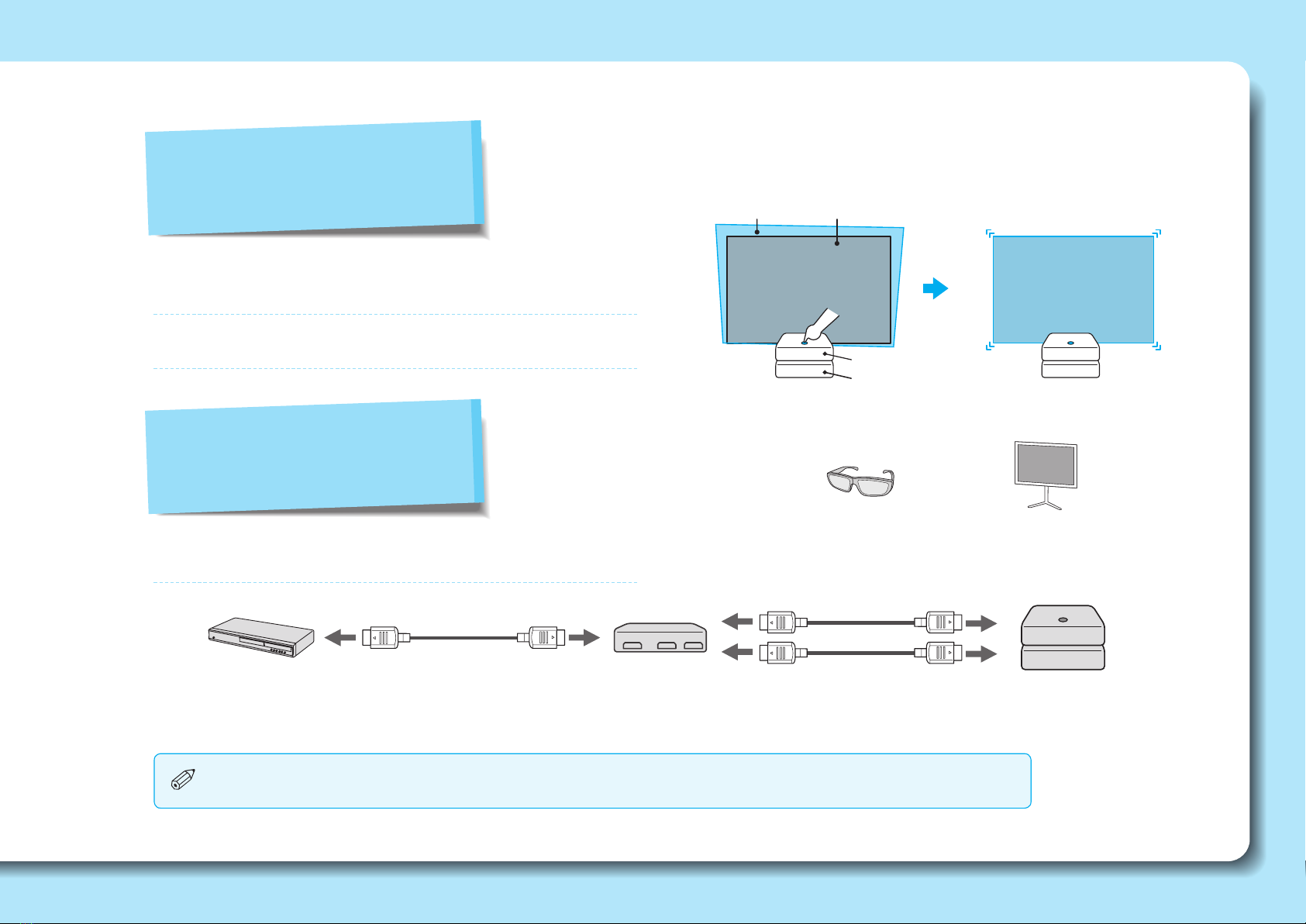
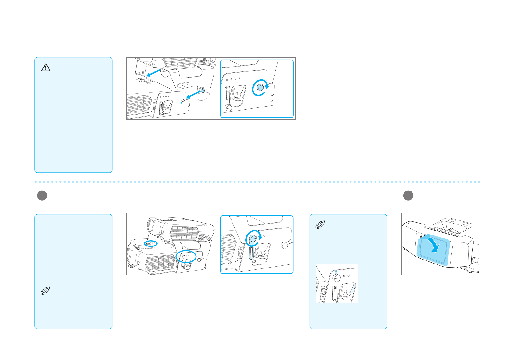
Carefully remove the protective
tape from the stack angle
adjustment screws, and then
remove the screws (on both the
left and right sides).
Secure the polarizing lters for
the commander and the receiver
with the supplied screws. Do not
overtighten the screws.
Stacking and
installing the
commander and the
receiver
Use the stacking
mounts to create a
stacked conguration
(one projector on top of
the other).
Setting Up
Loosen the screws for the commander's stacking mount connector (on
both the left and right sides).
3Stack the commander on top of the receiver.
1Attach the polarizing lters to the commander and the receiver.
2Attach the feet (when
setting up on a desk).
Warning
When assembling a
stacked conguration,
make sure you follow
these steps. If the
steps are not followed
correctly, the product
could fall, or your ngers
could get caught, which
could cause an injury.
There are numbers
on the bases of
the projectors, stacking
mounts, and polarizing
lters. Make sure the
numbers match when
assembling.
Commander
Receiver
88888

Place the screws into the holes, and then tighten them securely (on both
the left and right sides). Then tighten the commander's stacking mount
screws as well.
Attach the commander to the receiver by sliding the commander’s
stacking mount screws into the slots in the receiver’s stacking mount.
Then lightly tighten the screws (on both the left and right sides) to secure
the attachment.
4Secure the stacking mount angle adjustment with screws. 5Remove the clear
protective lm from the
polarizing lters.
Caution
When attaching the
commander to the
receiver, be careful not to
trap your ngers.
Place marking
stickers on the
positions where the
screws are secured. You
can then use these marks
when reassembling.
99999
There are screw holes
numbered 1 to 4 on
the left and right of the
stacking mount.
You can change the
commander's projection
angle by changing the
position secured by the
screw.
See "Screen Size and
Projection Distance"
on page 18 to determine
which screw hole to use.

1010101010
Connecting the
commander and the
receiver
You need to connect
a USB cable to link the
commander and the
receiver.
Connecting
Equipment
Commander
Commander
Receiver
Receiver
USB cable
Power cable
Power cable
Power inlet
Power inlet
1Plug in the power cables for the commander and the
receiver.
2Connect the commander's USB-A port to the receiver's
USB-B port with the supplied USB cable.
The projectors will not be linked if the wrong
USB ports are connected with the USB cable.
USB-A
USB-B
First, connect the power cables and the USB cable.

1111111111
1Connect the splitter to the computer with a VGA cable.
2Connect the commander and the receiver to the splitter
with VGA cables.
3Connect the commander or receiver to the computer with
an audio cable.
Audio is output from the connected projector.
First, check that the commander and the
receiver are properly connected with the
USB cable.
Next, obtain the following items (not included):
3 VGA cables
Audio cable (when outputting audio)
VGA splitter
•
•
•
•
•
Commander
Commander
Receiver
Receiver
Computer cable
(not included)
Computer cable
(not included)
Computer cable
(not included)
Audio cable
(not included)
Audio-L/R
Audio-L/R
Computer1
Computer1
Connecting to a
computer
Connecting with
computer cables
VGA splitter
(not included)

1212121212
1Connect the splitter to the computer with an HDMI cable. 2Connect the commander and the receiver to the splitter
with HDMI cables.
You can send the computer's audio with the projected image.
First, check that the commander and the
receiver are properly connected with the
USB cable.
Next, obtain the following items (not included):
3 HDMI cables
HDMI splitter
•
•
•
•
Commander
Receiver
HDMI cable
(not included) HDMI cable
(not included)
HDMI cable
(not included)
HDMI
splitter
(not included)
HDMI
HDMI
Connecting to a
computer
Connecting with HDMI
cables
When viewing 3D
images, make sure you
use HDMI cables and
an HDMI splitter that
support 3D signals.

1313131313
1Connect the splitter to the video equipment with an HDMI
cable.
2Connect the commander and the receiver to the splitter
with HDMI cables.
You can send the computer's audio with the projected image.
Commander
Receiver
HDMI cable
(not included) HDMI cable
(not included)
HDMI cable
(not included)
HDMI
splitter
(not included)
HDMI
HDMI
Connecting to
video equipment
Connecting with HDMI
cables
First, check that the commander and the
receiver are properly connected with the
USB cable.
Next, obtain the following items (not included):
3 HDMI cables
HDMI splitter
•
•
•
•
When viewing 3D
images, make sure you
use HDMI cables and
an HDMI splitter that
support 3D signals.

Superimposing the
images from the
commander and the
receiver
Perform this procedure
after setting up the
projectors.
Projecting
Images
Press the [ ] button on the
commander's control panel.
The commander and the receiver
turn on.
Hold down the [Screen Fit] button for about ve seconds.
The initial adjustment screen and the white and green
frames are displayed.
1Open the A/V mute
slides.
Open the A/V mute slides on the
commander and the receiver.
2Turn on the projectors. 3Display the adjustment screen
for the superimposed images.
Receiver frame
(green)
Commander frame
(white)
Approx.
ve seconds
The commander's control panel operates
both the commander and the receiver.
Perform projector operations from the
commander's control panel.
The following icon is displayed when
turning the projector system on. The
projector indicated by the arrow is the
subject of any displayed status message.
•
•
Commander
Receiver
Surround the receiver's frame with the commander's
frame.
Adjust the commander's frame (white) so that it is outside the
receiver's frame (green).
Adjust the focus for the commander and receiver.
Superimpose the images.
Size the receiver's frame.
Adjust the receiver's projection size to t the screen.
When suspending
the projectors from
a ceiling, change the
Projection mode before
superimposing the
images. You can change
the Projection mode by
holding down the [A/V
Mute] button on the
remote control for about
ve seconds.
1414141414
Superimposing Images

The white frame is used to adjust
the commander, and the green
frame is used to adjust the
receiver.
4Adjust the projection
position.
5Adjust the focus for the commander and the receiver.
7Correct keystone
distortion for the
receiver's frame (green).
If the projection system is on a
desk, extend or retract the feet to
adjust the position. The rear feet
adjust the horizontal tilt and the
front foot adjusts the height.
If the system is suspended from
a ceiling, see the User's Guide
supplied with the ceiling mount.
Use the commander's focus
ring to adjust the focus for the
projected image.
Select Display the test pattern,
and then press the [ ] button.
Select the projector you want to
adjust, and then press the [ ]
button.
The test pattern is displayed.
Use the focus ring on the
projector you want to adjust.
When you have nished
correcting the focus, press the
[Esc] button.
Next, select the other projector
from the test pattern menu and
repeat the focus adjustment
procedure described above.
Select Perform keystone
correction for the Receiver.
Next, use either the
H/V - keystone or Quick Corner®
method as described on the
next page.
When you have nished
correcting the focus for the
commander and the receiver,
press the [Esc] button until you
see the initial adjustment screen
again.
6Adjust the projection size for the receiver.
Use the receiver's zoom ring
to adjust the receiver's frame
(green) to the projection size
you want.
Receiver
frame
Commander
frame
Do not maximize the
zoom for the receiver
because the commander's
frame needs to be larger
than the receiver's frame.
See "Screen Size and
Projection Distance" on
page 18 to determine the
projection size.
1515151515

8Adjust the projection size for the commander's frame
(white).
Select Quick Corner.Select Perform keystone
correction for the Receiver.
Use the commander's zoom ring
to adjust the commander's frame
(white) so that it is outside the
receiver's frame (green).
Use the [ ] [ ] [ ] [ ]
buttons to correct the position of
the corners.
Correct each corner as necessary.
Press the [Esc] button to nish
making settings.
When you have nished making
corrections, press the [Esc]
button until you see the initial
adjustment screen again.
Use the [ ] [ ] [ ] [ ]
buttons to select the corner you
want to correct, and then press
the [ ] button.
Use the [ ] [ ] buttons to
select the direction you want
to correct, and then press the
[ ] [ ] buttons to make
corrections.
Press the [Esc] button to nish
making settings.
When you have nished making
corrections, press the [Esc]
button until you see the initial
adjustment screen again.
Commander
frame
Receiver
frame
Select H/V-Keystone.
1616161616
For best results, minimize the
dierence in size between
the receiver's frame (green)
and the commander's frame
(white).
The images can still be
superimposed even if the
commander's frame is outside
the screen.
If you have trouble adjusting
the frames, make sure you
selected the correct screw hole
when you adjusted the angle
between the projectors. See
“Screen Size and Projection
Distance”on page 18 to
determine which screw hole
to use.
•
•
•
Correcting using
Quick Corner
Correct the four corners of the receiver's
frame (green) individually.
Correcting using
H/V-Keystone
Correct keystone distortion for the receiver's frame (green).

9Superimpose two images.
Press the [Screen Fit] button. The images from the
commander and the receiver are
automatically superimposed.
If you need to ne tune
the superimposed
images
If you need to make ne
adjustments, select Yes, and then
press the [ ] button.
The manual adjustment screen is
displayed.
If you need to make ne
adjustments, see the next
section.
If you have nished making
adjustments, select No, and then
press the [ ] button.
2Correct the four corners individually.
The white pattern is for adjusting
the commander, and the green
pattern is for adjusting the
receiver.
1Adjust both projected
images manually.
Use the [ ] [ ] [ ] [ ]
buttons to correct the position of
the corners.
Correct each corner as necessary.
Press the [Esc] button to nish
making settings.
Use the [ ] [ ] [ ] [ ]
buttons to select the corner you
want to correct, and then press
the [ ] button.
When adjusting
each corner individually,
adjust so that the white
and green patterns
overlap to create one
pattern.
1717171717

18
Screen Size and Projection Distance
16:10
Screen
Size
1
2 4
Minimum to Maximum
80” 97”-106”(248-270 cm) 3.8”(10 cm) 4
90” 110”-120”(279-304 cm) 4.3”(11 cm)
100” 122”-133”(310-338 cm) 4.7”(12 cm) 3
110” 134”-147”(341-372 cm) 5.2”(13 cm)
120” 147”-160”(373-407 cm) 5.7”(14 cm) 2
130” 159”-174”(404-441 cm) 6.2”(16 cm)
140” 171”-187”(435-475 cm) 6.6”(17 cm) 1
150” 184”-200”(467-509 cm) 7.1”(18 cm)
16:9
Screen
Size
1
2 4
Minimum to Maximum
80” 100”-109”(255-278 cm) 1.7”(4 cm) 4
90” 113”-123”(287-313 cm) 1.9”(5 cm)
100” 125”-137”(319-348 cm) 2.1”(5 cm) 3
110” 138”-151”(351-383 cm) 2.4”(6 cm)
120” 151”-165”(383-418 cm) 2.6”(7 cm) 2
130” 163”-178”(415-453 cm) 2.8”(7 cm)
140” 176”-192”(447-488 cm) 3”(8 cm) 1
150” 189”-206”(479-523 cm) 3.2”(8 cm)
4:3
Screen
Size
1
2 4
Minimum to Maximum
80” 110”-121”(281-306 cm) 4.3”(11 cm) 4
90” 124”-136”(316-345 cm) 4.8”(12 cm) 3
100” 138”-151”(351-383 cm) 5.4”(14 cm)
110” 152”-166”(387-422 cm) 5.9”(15 cm) 2
120” 166”-181”(422-461 cm) 6.4”(16 cm)
130” 180”-197”(458-499 cm) 7”(18 cm)
1
140” 194”-212”(493-538 cm) 7.5”(19 cm)
150” 208”-227”(529-577 cm) 8”(20 cm)
Silver screen (for viewing 3D images)•
Screen Size 56 7
Up to 120” 97”-181”(248-461 cm) Approx. 10° maximum Approx. 10° maximum
Other projection surfaces (for viewing 2D images)•
Screen Size 5 6 7
Up to 150”50”0” 97”-227”(248-577 cm) Approx.15° maximum Approx.15° maximum
1Projection distance
2Distance from the center of the receiver's
lens to the base of the screen (or to top of
the screen, if suspended from a ceiling)
3Center of receiver's lens
4Screw hole numbers (for angle adjustment)
5Distance from projector to
screen
6Horizontal angle
7Vertical angle
When viewing 3D images, you can use screen sizes up to 120”.
Range for superimposing two images
Conversion gures in these tables may have been rounded up or down.

19
About the LED Indicators
Indicator status during normal operation
Orange Standby Press to start projection.
Green Warm-up in progress is unavailable for about 30 seconds.
Green Projection in
progress The projector is operating normally.
Indicator status during an error/warning
Red
Red
Red
Internal Error
Disconnect the power cable from the electrical
outlet, and contact Epson.
Red
Red
Fan Error
Sensor Error
Red
Red
High Temp Error
Wait for about ve
minutes, and then
disconnect the power
cable from the electrical
outlet.
Check the following points.
If the projectors are positioned next to a wall,
move them farther away from the wall.
Clean or replace the air lter.
Make sure nothing is blocking the vents.
•
•
•
Red
Orange
High Temp Warning
Red
Red
Lamp Error
Lamp Failure
Check the following points.
Remove the lamp and check that it is not
damaged. If it is not damaged, reinstall the
lamp and turn on the projector. If it is damaged,
contact Epson.
Check that the lamp and the lamp cover are
securely installed.
Clean the air lter.
•
•
•
Orange Replace Lamp Replace the lamp as soon as possible. The lamp
may fail if you continue to use it in this condition.
Red
Red
Red
Auto Iris Error
Power Error
Disconnect the power cable from the electrical
outlet, and contact Epson.Epson..
If the error continues to occur after checking the points above, disconnect the power cable from
the electrical outlet, and contact Epson.
The LED indicators change according to the status of the commander and the receiver. For more troubleshooting information, see your online User's Guide.
On Flashing O

20
Troubleshooting
You can’t get the adjustment screen with the white and green frames to display.
Make sure you press and hold the [Screen Fit] button for at least 5 seconds. Do not release the [Screen Fit] button until you see the frames.
You see a Screen Fit has not been executed completely message while you are trying to start the Screen Fit process.
Press the [ ] button to clear the error, then press and hold the [Screen Fit] button (for at least 5 seconds) until you see the white and green frames on the screen. Do not
release the [Screen Fit] button until you see the frames.
The Receiver does not turn on when you turn on the Commander.
Make sure the USB cable is properly connected.
Where to get help
Manual
For more information about using the projector, click the icon on your desktop to access the online manual (requires an Internet connection). If you don’t have a User’s Guide
icon, you can install it from the projector CD or go to the Epson website, as described below.
Telephone support services
To use the EPSON® PrivateLine® Support service, call (800) 637-7661. This service is available 6 AM to 8 PM, Pacific Time, Monday through Friday, for the duration of your warranty
period.
You may also speak with a support specialist by calling (562) 276-4394 (U.S.) or (905) 709-3839 (Canada), 6 AM to 8 PM, Pacific Time, Monday through Friday, and 7 AM to 4 PM,
Pacific Time, Saturday.
Days and hours of support are subject to change without notice. Toll or long distance charges may apply.
Internet support
Visit www.epson.com/support (U.S.) or www.epson.ca/support (Canada) for solutions to common problems. You can download utilities and documentation, get FAQs and
troubleshooting advice, or e-mail Epson.
Registration
Register today to get product updates, special promotions, and customer-only offers. You can use the CD included with your projector or register online at
www.epson.com/webreg.
Other manuals for PowerLite W16SK
2
Table of contents
Languages:
Other Epson Projection Screen manuals
Popular Projection Screen manuals by other brands

Da-Lite
Da-Lite Da-Glas Handling and care of

Elite Screens
Elite Screens Osprey Tension Dual Series Adjustment instructions

Grandview
Grandview FC-M instruction manual

Elite Screens
Elite Screens Kestrel Series user guide

Elite Screens
Elite Screens M135XWV2 user guide

Euroscreen
Euroscreen Diplomat Electric manual

VITRA
VITRA Tyde 2 Instructions for use

Screen Innovations
Screen Innovations 5 Motorized owner's manual

Elite Screens
Elite Screens TE100HC2 supplementary guide

REMACO TECHNOLOGIES
REMACO TECHNOLOGIES PRO-L3030 manual

Projecta
Projecta Cinema Electrol Mounting instruction

EPV
EPV Polar Star eFinity Series user guide