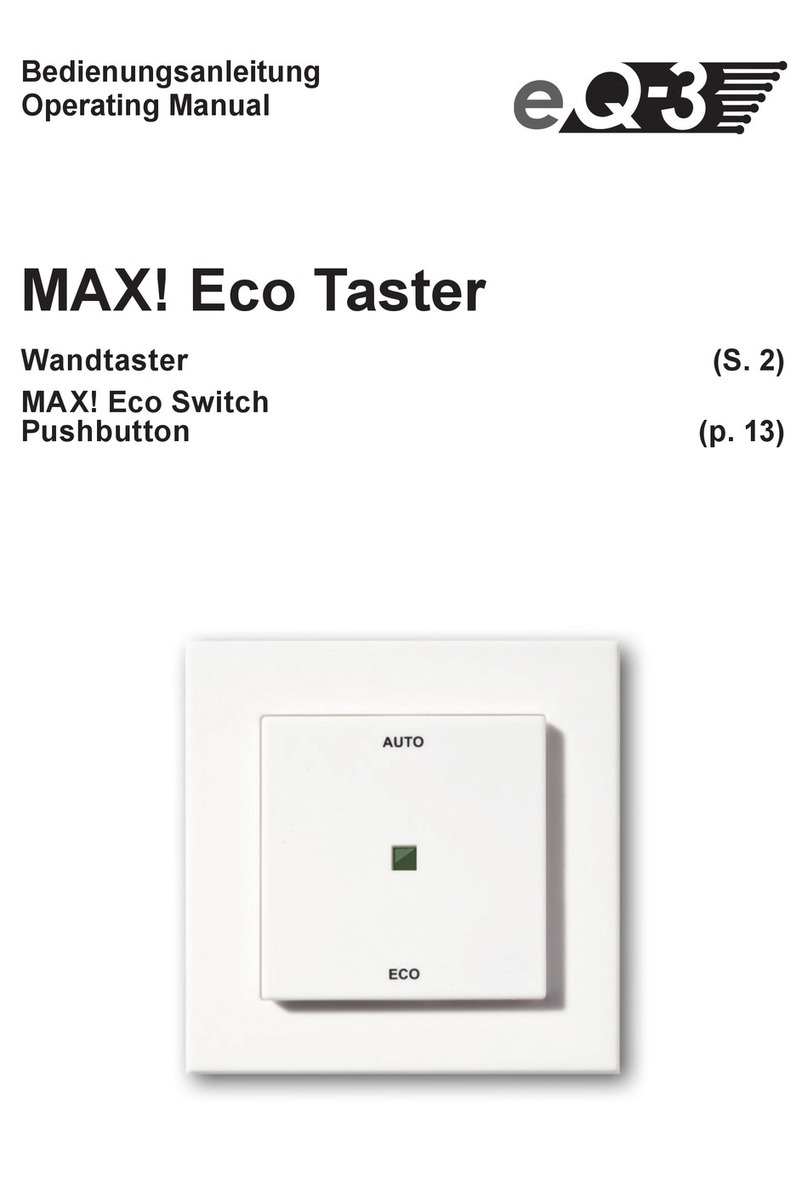
EQ3 MAX! Eco Switch User manual

1
Bedienungsanleitung
Operating Manual
Mode d’emploi
Handleiding
MAX! Eco Taster
Wandtaster (S. 2)
MAX! Eco Switch
Pushbutton (p. 12)
MAX! Bouton mural
Bouton mural (p. 22)
MAX! Wandschakelaar
Wandschakelaar (p. 32)

2
Inhaltsverzeichnis
1. Bestimmungsgemäßer Einsatz...................................3
2. Übersicht.....................................................................4
3. Sicherheitshinweise ....................................................4
4. Entsorgungshinweise..................................................5
5. Batterien einlegen (wechseln) ....................................5
6. Montage ......................................................................6
7. Anlernen an MAX! Komponenten...............................7
8. Ablernen / Reset .........................................................8
9. LED-Blinkfolgen und Sendeverhalten........................8
10. Montage in bestehende Schalterserien.....................9
11. Hinweise zum Funkbetrieb .........................................9
12. Technische Eigenschaften........................................10
Lesen Sie diese Anleitung sorgfältig, bevor Sie das Gerät in Be-
trieb nehmen. Bewahren Sie die Anleitung zum späteren Nach-
schlagen auf.
1. Ausgabe Deutsch 03/2011
Dokumentation © 2011 eQ-3 Ltd., Hong Kong.
Alle Rechte vorbehalten.
BC-PB-2-WM, V1.1, 099013

3
1. Bestimmungsgemäßer Einsatz
Der MAX! Eco Taster erfüllt im MAX! System eine speziel-
le Aufgabe. Wenn man das Haus oder die Wohnung ver-
lässt, können alle Räume durch einen Tastendruck in den
manuellen Modus und auf Absenktemperatur geschaltet
werden. Wenn man das Haus oder die Wohnung wieder
betritt, können ebenfalls auf Tastendruck alle MAX! Kom-
ponenten auf Auto-Betrieb gestellt werden, um so die indi-
viduellen Wochenheizprogramme für die Räume zu starten.
Die Kommunikation der MAX! Komponenten untereinander
erfolgt bidirektional. Somit ist dafür gesorgt, dass gesen-
dete Informationen den Empfänger erreichen.
Der MAX! Eco Taster ist batteriebetrieben und bietet des-
halb eine hohe Flexibilität bei der Montage und Wahl des
Montageortes. Installation und Demontage gestalten sich
durch Schrauben oder Kleben auf unterschiedlichen Un-
tergründen wie Mauerwerk, Möbeln, Fliesen oder Glas
sehr einfach. Ein Stemmen oder Schlitzen von Mauerwerk
ist nicht erforderlich.
Die Wandmontage kann im mitgelieferten Rahmen erfol-
gen. Zusätzlich ist es auch möglich, den MAX! Eco Taster in
bestehende Schalterserien zu integrieren, auch wenn keine
Unterputzdose vorhanden ist (näheres in Kapitel 10).
Betreiben Sie das Gerät nur in Innenräumen und vermei-
den Sie den Einfluss von Feuchtigkeit, Staub sowie Son-
nen- oder Wärmebestrahlung.
Jeder andere Einsatz als in dieser Bedienungsanleitung
beschrieben ist nicht bestimmungsgemäß und führ t zu Ga-
rantie- und Haftungsausschluss. Dies gilt auch für Um-

4
bauten und Veränderungen. Die Geräte sind ausschließ-
lich für den privaten Gebrauch gedacht.
Weitere Informationen zum MA X! System und den ver fügba-
ren Komponenten erhalten Sie unter www.eQ-3.de/MAX
2. Übersicht
(A) Montageplatte
(B) Wechselrahmen
(C) Elektronikeinheit/Taster
3. Sicherheitshinweise
Das Gerät ist kein Spielzeug, erlauben Sie Kindern nicht
damit zu spielen. Verpackungsmaterial bitte nicht achtlos
liegen lassen, dies kann für Kinder zu einem gefährlichen
Spielzeug werden. Öffnen Sie das Gerät nicht, es enthält
keine durch den Anwender zu wartenden Teile. Im Fehler-
fall schicken Sie das Gerät an den Service.
A
B
C

5
4. Entsorgungshinweise
Gerät nicht im Hausmüll entsorgen!
Elektronische Geräte sind entsprechend der Richt-
linie über Elektro- und Elektronik- Altgeräte über
die örtlichen Sammelstellen für Elektronik-Altge-
räte zu entsorgen!
Das CE-Zeichen ist ein Freiverkehrszeichen, das
sich ausschließlich an die Behörden wendet und
keine Zusicherung von Eigenschaften beinhaltet.
Verbrauchte Batterien gehören nicht in den
Hausmüll! Entsorgen Sie diese in Ihrer örtlichen
Batteriesammelstelle!
5. Batterien einlegen (wechseln)
Im montierten Zustand lässt sich der•
Taster einfach aus dem Rahmen und
von der Montageplatte ziehen. Fas-
sen Sie dazu die Tastwippe seitlich an
und ziehen Sie den Taster heraus. Ein
Entfernen der Wippe oder Öffnen des
Gerätes ist nicht erforderlich
Drehen Sie den Taster auf die Rückseite•
Nach Entnahme der Batterien sollte ca. 60 Sekunden•
gewartet werden.
Legen Sie 2 LR03 Batterien (Micro/AAA) polungsrichtig•
in die Batteriefächer ein.
Setzen Sie den Taster wieder in den Rahmen.•
Normale Batterien dürfen niemals aufgeladen wer-
den. Es besteht Explosionsgefahr. Batterien nicht
ins Feuer werfen! Batterien nicht kurzschließen!

6
6. Montage
Sie können den MAX! Eco Taster entweder im beiliegen-
den Rahmen an eine Wand schrauben/kleben oder in eine
bestehende Schalterserie integrieren (näheres zur Kom-
patibilität finden Sie in Abschnitt 10).
Klebestreifen-Montage:
Der Untergrund muss sauber und trocken sein!
Bringen Sie die Klebestreifen auf der Rückseite der•
Montageplatte an.
Entfernen Sie die Folie von den Klebestreifen.•
Drücken Sie die Montageplatte mit der Rückseite an•
der Stelle an die Wand, wo der MAX! Eco Taster zu-
künftig hängen soll. Der Pfeil der Montageplatte sollte
nach oben zeigen.
Setzen Sie den Wechselrahmen auf die Montageplatte.•
Setzen Sie die Elektronikeinheit in den Wechselrah-•
men, auf die Montageplatte. Achten Sie darauf, dass
die Klammern der Montageplatte in die Öffnungen der
Elektronikeinheit rasten.
Schraub-Montage:
Setzen Sie die Montageplatte an die Wand. Achten•
Sie darauf, dass der Pfeil auf der Montageplatte nach
oben zeigt.
Zeichnen Sie die Bohrlöcher (a) der Montageplatte mit•
einem Stift an der Wand an.
Ve r w e n d e n S i e z u m b e f e s t i g e n d i e m i t g e l i e fe r t e n S c h r a u -•
ben und Dübel.
Bringen Sie nun den Wechselrahmen auf der Monta-•
geplatte an.

7
Setzen Sie den Taster ein. Achten Sie darauf, dass die•
Klammern der Montageplatte in die Öffnungen der Elek-
tronikeinheit rasten.
Bei der Montage auf einer Unterputzdose müssen kei-
ne Löcher gebohrt oder Dübel verwendet werden .
Sie können ebenso den Rahmen eines anderen Her-
stellers verwenden oder die Elektronikeinheit in ei-
nen Mehrfachrahmen integrieren. Lesen Sie bzgl. der
Kompatibilität den Abschnitt 10.
7. Anlernen an MAX! Komponenten
Damit MAX! Komponenten miteinan-
der kommunizieren können, müssen
Sie aneinander angelernt sein.
• Versetzen Sie zunächst den Anlern
partner, so z.B. den MAX! Cube, in
den Anlernmodus.
• Drücken Sie eine der Tasten des MAX!
Eco Tasters länger als 3 Sekunden, um den Anlernmodus
zu aktivieren. Im Anlernmodus blinkt die LED.
Das erfolgreiche Anlernen des MAX! Eco Taster wird•
durch einmaliges Aufleuchten der LED bestätigt. Sollte
kein Anlernen erfolgen, deaktiviert sich der Anlernvor-
gang automatisch nach 30 Sekunden.
a a

8
Der MAX! Eco Taster kommuniziert nur zentral über
den MAX! Cube mit den MAX! Komponenten. Fällt
diese zentrale Schnittstelle aus, können MAX! Kom-
ponenten Befehle vom MAX! Eco Taster nicht mehr
empfangen.
8. Ablernen / Reset
Der Auslieferungszustand des MAX! Eco Tasters kann
manuell wieder hergestellt werden. Dabei gehen alle
Einstellungen und Informationen über angelernte Gerä-
te verloren.
Entnehmen Sie zunächst die Batterien aus dem Bat-•
teriefach.
Warten Sie 60 Sekunden.•
Halten Sie die obere oder untere Taste gedrückt.•
Legen Sie gleichzeitig die Batterien wieder ein.•
Halten Sie die Taste so lang gedrückt, bis die Geräte-•
LED zu blinken beginnt.
Lassen Sie die Taste los. Die Werkseinstellungen sind•
wieder hergestellt.
9. LED-Blinkfolgen und Sendeverhalten
Die Blinkfolge der LED hat unterschiedliche Bedeutungen:
Blinkfolge Bedeutung
1x Blinken Bestätigung nach erfolgreichem Senden
des Funkbefehls
2x Blinken DutyCycle Limit erreicht. Senden nach
spätestens einer Stunde wieder möglich.
3x Blinken Fehlermeldung, Funkbefehl wurde nicht
erfolgreich übertragen

9
10. Montage in bestehende Schalterserien
Der MAX! Eco Taster passt in die Rahmen folgender
Hersteller:
11. Hinweise zum Funkbetrieb
Die Funk-Übertragung wird auf einem nicht exklusiven
Übertragungsweg realisiert, weshalb Störungen nicht aus-
geschlossen werden können. Störeinflüsse können u.a.
durch Schaltvorgänge, Elektromotoren oder auch defek-
te Elektrogeräte hervorgerufen werden.
Die Reichweite in Gebäuden kann stark von der im Frei-
feld abweichen. Außer der Sendeleistung und den Emp-
fangseigenschaften der Empfänger spielen Umwelteinflüs-
se wie Luftfeuchtigkeit neben baulichen Gegebenheiten
eine wichtige Rolle.
Hiermit erklärt die eQ-3 Entwicklung GmbH, dass sich
dieses Gerät in Übereinstimmung mit den grundlegenden
Anforderungen und den anderen relevanten Vorschriften
der Richtlinie 1999/5/EG befindet. Die vollständige Konfor-
mitätserklärung finden Sie unter www.eQ-3.de.
Hersteller Rahmen
Berker S.1, B.1, B.3, B.7 Glas
ELSO Joy
GIRA System 55, Standard 55, E2,
E22, Event, Espirit
merten 1-M, Atelier-M, M-Smart,
M-Arc, M-Star, M-Plan
JUNG A 500, AS 500, A plus, A
creation

10
12. Technische Daten
Versorgungsspannung: 3 V
Batterien: 2x LR03 (Micro / AAA)
Batterielebensdauer: ca. 5 Jahre
Empfängerfrequenz: 868,3 MHz
Empfängerklasse: SRD Class 2
Typische Reichweite im Freifeld: 100 m
Gehäuseabmessungen: 86 x 86 x 16,5 mm
(B x H x T)
Technische Änderungen sind vorbehalten.


12
Table of contents
1. Intended use .............................................................13
2. Overview....................................................................14
3. Safety instructions.................................................... 14
4. Instructions for disposal ...........................................15
5. Inserting (replacing) batteries...................................15
6. Mounting ...................................................................16
7. Teaching-in on MAX! Components .......................... 17
8. Teach-out/Reset ....................................................... 18
9. LED flashing sequences and
transmission behaviour ............................................18
10. Mounting in existing switches ..................................19
11. Information about radio operation ...........................19
12. Technical characteristics..........................................20
Read this manual carefully before starting to use the device.
Keep the manual so you can refer to it at a later date should you
need to.
1st English edition 03/2011
Documentation © 2011 eQ-3 Ltd., Hong Kong.
All rights reserved.
BC-PB-2-WM, V1.1, 099013

13
1. Intended use
The MAX! Eco Switch has a special job to do in the MAX!
System. When you leave your house or apartment, all
rooms can be switched to manual mode and reduction
temperature at the touch of a button. Similarly, when
you return home, all MAX! Components can be set to
automatic operation at the touch of a button, thereby
starting the separate weekly heating programs configured
for each room. Communication between MAX! Compo-
nents is bi-directional. This ensures that the information
sent reaches the recipient.
The MAX! Eco Switch is battery-operated. As such it is
highly flexible where mounting and selecting a mounting
location are concerned. The MAX! Eco Switch is mounted
and removed very easily using screws or adhesive strips.
It is compatible with a number of different sur faces includ-
ing furniture, brick walls, tiles or glass. Holes or slits do
not have to be chiselled out of brick walls. The frame sup-
plied with the device can be used for wall mounting. It is
also possible to integrate the MAX! Eco Switch into exist-
ing switches, even if a flush-mounting box is not already
present. (See Section 10 for more detailed information.)
The device may only be operated indoors and must be
protected from the effects of damp and dust, as well as
solar or heat radiation.
Using this device for any purpose other than that
described in this operating manual does not fall with-
in the scope of intended use and shall invalidate any
warranty or liability. This also applies to any conversion
or modification work.

14
This device is intended for private use only.
For more information about the MA X! System and the avail-
able components, please go to www.eQ-3.de/MAX.
2. Overview
(A) Mounting plate
(B) Attachment frame
(C) Electronic unit/pushbutton
3. Safety instructions
This device is not a toy; do not allow children to play with
it. Do not leave packaging material lying around, as it can
be dangerous in the hands of a child. Do not open the
device: it does not contain any components that need to
be serviced by the user. In the event of an error, please
return the device to our service department.
A
B
C

15
4. Instructions for disposal
Do not dispose of the device with regular domestic waste.
Electronic equipment must be disposed of at
local collection points for waste electronic equip-
ment in compliance with the Waste Electrical and
Electronic Equipment Directive.
The CE Marking is simply an official symbol
relating to the free movement of a product; it does
not warrant a product’s characteristics.
Used batteries should not be disposed of with
regular domestic waste! Instead, take them to
your local battery disposal point.
5. Inserting (replacing) batteries
Once mounted, the pushbutton can•
easily be pulled out of the frame. To
remove the pushbutton from the frame,
take hold of the sides of the pushbut-
ton rocker and pull the pushbutton out.
You do not need to remove the rocker or
open the device.
Turn the pushbutton over.•
After removing the old batteries , please wait approximately•
60 seconds before inserting the new ones.
Insert2LR03(micro/AAA)batteriesinthebatterycompartments•
(making sure that you insert them the right way round).
Put the pushbutton back into the frame.•
Never recharge standard batteries. Doing so will
present a risk of explosion. Do not throw the batter-
ies into a fire. Do not short-circuit batteries.

16
6. Mounting
You can either use screws or adhesive strips to mount the
MAX! Eco Switch to a wall in the frame supplied or integrate
it into an existing switch (see Section 10 for more detailed
information about compatible switches).
Adhesive strip mounting:
The sur face on which you are mounting the
pushbutton must be clean and dry.
Attach the adhesive strips to the rear of the•
mounting plate.
Remove the protective film from the adhesive strips.•
Press the rear of the mounting plate to the wall where•
the MAX! Eco Switch will subsequently be attached. The
arrow on the mounting plate should point upwards.
Attach the frame to the mounting plate.•
Attach the electronic unit to the frame, on the mounting•
plate. Make sure that the clips on the mounting plate
latch into the openings on the electronic unit.
Screw mounting:
Position the mounting plate on the wall. Make sure that•
the arrow on the mounting plate is pointing upwards.
Use a pen to mark the positions of the bore holes (a) in•
the mounting plate on the wall.
Use the screws and plugs supplied to fasten the plate•
to the wall.
Next, attach the frame to the mounting plate.•
Attach the pushbutton. Make sure that the clips on•
the mounting plate latch into the openings on the
electronic unit.

17
Holes do not have to be drilled and plugs do not have
to be used for mounting on a flush-mounting box.
You can even use a frame supplied by another
manufacturer or integrate the electronic unit into
a multi-gang frame. Read the information about
compatibility in Section 10.
7. Teaching-in on MAX! Components
In order to enable communication be-
tween MAX! Components, the devices
have to be taught-in to one another.
Start by switching the teach-in•
partner(e.g.the MAX! Cube)toteach-
in mode.
To activate teach-in mode, press and hold down one of•
the buttons on the MAX! Eco Switch for at least 3 sec-
onds. The LED flashes in teach-in mode.
Successful teaching-in of the MAX! Eco Switch is•
confirmed by the LED lighting up once. If you do
not teach-in any devices, the teach-in procedure
deactivates automatically after 30 s.
a a

18
The MAX! Eco Switch communicates with the MAX!
Components only centrally via the MAX! Cube. If this
central interface fails, MA X! Components can no long-
er receive commands from the MAX! Eco Switch.
8. Teach-out/Reset
The MAX! Eco Switch can be reset to the initial state
manually. Restoring the initial state deletes all settings and
information about taught-in devices.
First re move the batteries from the batter y•
compartment.
Wait 60 seconds.•
Press and hold down the button at the top or bottom.•
Re-insert the batteries at the same time.•
Press and hold down the button until the device LED•
starts to flash.
Release the button. The factory settings are restored.•
9. LED flashing sequences and
transmission behaviour
The LED’s flashing sequences have different meanings:
Flashing sequence Meaning
1x flash Confirmation following successful sending
of the radio command
2x flashes Duty cycle has been exceeded. The
longest period to wait before sending again
would be an hour.
3x flashes Error message, radio command not sent
successfully

19
10. Mounting in existing switches
The MAX! Eco Switch is designed to fit into frames
supplied by the following manufacturers:
11. Information about radio operation
Radio transmission is performed on a non-exclusive
transmission path, which means that there is a possibility
of interference occurring. Interference can also be caused
by switching operations, electrical motors or defective
electrical devices.
The range of transmission within buildings can differ
greatly from that available in the open air. Besides the
transmitting power and the reception characteristics of
the receiver, environmental factors such as humidity in
the vicinity have an important role to play, as do on-site
structural/screening conditions.
eQ-3 Entwicklung GmbH hereby declares that this de-
vice complies with the essential requirements and other
relevant regulations of Directive 1999/5/EC. You can find
the full declaration of conformity at www.eQ-3.de.
Manufacturer Frame
Berker S.1, B.1, B.3, B.7 glass
ELSO Joy
GIRA System 55, Standard 55, E2,
E22, Event, Espirit
merten 1-M, Atelier-M, M-Smart,
M-Arc, M-Star, M-Plan
JUNG A 500, AS 500, A plus, A
creation

20
12. Technical data
Supply voltage: 3 V
Batteries: 2x LR03 (micro/AAA)
Battery life: 5 years approx.
Receiver frequency: 868.3 MHz
Receiver class: SRD Class 2
Typical range of transmission
in the open air: 100 m
Housing dimensions: 86 x 86 x 16.5 mm
(W x H x D)
Subject to technical changes.
Table of contents
Languages:
Other EQ3 Switch manuals

