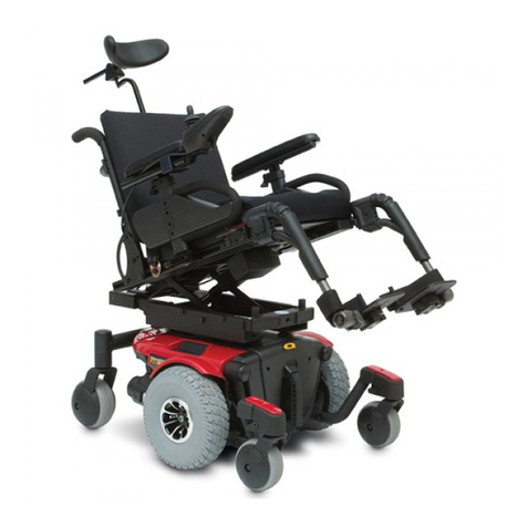
Equalizer TILT SYSTEM Manual

22
PN30175
Revised 1109
EQTiltOM_PN30175.ind
Set Your Own Pace!
OWNER’S OPERATOR
AND MAINTENANCE MANUAL
DEALER: THIS MANUAL MUST BE GIVEN TO THE USER OF THE WHEELCHAIR.
Tilt System
USER: BEFORE USING YOUR NEW EQUALIZER TILT SYSTEM,
READ THIS MANUAL
AND SAVE FOR FUTURE REFERENCE.

1
PN 30175
Revised 1109
EQTiltOM_PN30175.indd
Table of Contents
THIS MANUAL COVERS THE OPERATION OF YOUR NEW
EQUALIZER TILTSYSTEM . BE SURE AND FIND THE
INFORMATION THAT PERTAINS TO YOUR NEEDS BEFORE OPERATING.
Introduction 3
Warnings 4
Safety Summary 5
Operating Information 6
Safety/Handling of seating systems/wheelchairs 10
Specications 12
Operating the Tilt functions 13
Set Up Adjustments 16
Common Accessories and Routine Maintenance 19
Troubleshooting 20
LimitedWarranty 21

2
Equalizer Tilt System OWNERS MANUAL rev. 8/26/04
The Equalizer tilt seating system is an adjustable seating system that can be or-
dered from the factory with a few predetermined set up instructions requested by
the equipment provider purchasing the equipment from Leisure-Lift. All decisions
regarding the appropriate set up of the seating system, the power base, the pro-
grammable controller settings, and the stability rating of the nal product must be
made based on direct interaction between end users and their local equipment
provider or therapist. Unlike a local equipment provider or therapist, Leisure-Lift
does not have sufcient knowledge of your needs and environment to determine
what limitations, accommodations, and adjustments are needed.
In a Rehab situation, where this wheelchair (or any other) has been augmented
with other products, RESNA has determined it is the therapists’ or dealers respon-
sibility to determine that the nal conguration is safe for the specic user. RES-
NA also states that the user be given a “safe stability curve in all three planes.
RESNA is an organization of manufacturers, the V.A., the F.D.A., Academe and
Medical Professionals that set standards and accreditation for the US.
Your Authorized Leisure-Lift dealer is:
Dealer:
Address:
City: State: Zip:
Phone:
Your Serial Number is: Purchase Date:
THIS MANUAL IS INTENDED AS A SUPPLEMENT TO THE IN-SERVICE TRAINING PROVID-
ED BY YOUR THERAPIST AND PROVIDER.

3
Equalizer Tilt System OWNERS MANUAL
Introduction
We at Leisure-Lift want to thank you for purchasing our Equal-
izerTiltSystem.EqualizerisdesignedspecicallyforLeisure-Liftpowerchairs.
It is fully adjustable to meet the individual needs of the user.
Important
It is important that you read, understand and follow the operating
instructions and safety precautions before operating the Equalizer Tilt Sys-
tem.
Choose the right Tilt seating adjustment & options. Leisure-Lift's Equalizer
Tilt is available in many sizes, adjustments & options to meet the needs of the
rider. However the selection of the seating system rests solely with you and
your healthcare professional. Choosing the best system for you depends on
such things as:
A) Your size, disability balance, strength & coordination.
B) Your level of activity and individual use.
C) The type of hazards you must overcome in daily use.
The local areas where you are likely to use your system.
D) The need for options for your safety & comfort.
Adjust the seating system to your ability. You must work with your doctor,
therapist&suppliertottheseatingsystemtoyouandadjustthecontrol
settings for your level of function and ability.
Before using the Equalizer Tilt System you and each person who may assist
you should read this entire manual and make sure to follow all instructions.
Review the warnings daily until they are second nature to you.

4
WARNING
DO NOT OPERATE THIS EQUIPMENT WITHOUT FIRST READING AND
UNDERSTANDING THIS MANUAL AND THE MANUAL PROVIDED WITH THE
WHEELCHAIR. THIS MANUAL IS INTENDED AS A SUPPLEMENT TO THE IN-SER-
VICE TRAINING PROVIDED BY YOUR AUTHORIZED PROVIDER. IF YOU ARE
UNABLE TO UNDERSTAND THE WARNINGS AND INSTRUCTIONS, CONTACT A
LEISURE-LIFT DEALER OR LEISURE-LIFT TECHNICAL SUPPORT BEFORE AT-
TEMPTING TO USE THIS EQUIPMENT - OTHERWISE INJURY OR DAMAGE MAY
RESULT.
SAVE THESE INSTRUCTIONS.
PRODUCTS SAFETY LABELS
The symbols below are used throughout this manual and on the product to
identify warnings, cautions, and notes. It is very important for you to read and
understand the information that follows these symbols completely.
WARNING! Indicates a potentially hazardous situation
which, if not avoided, could result in death or serious injury.
CAUTION! Indicates a potentially hazardous situation which,
if not avoided, may result in minor or moderate injury
and/or property damage.
NOTE: Indicates important things to remember when using
your Equalizer.
WARNING/CAUTION notices as used in this manual apply to hazards or unsafe
practices which could result in personal injury or property damage.
SEATING SYSTEM/WHEELCHAIR USER
As a manufacturer of wheelchairs and seating systems, Leisure-Lift builds many wheelchairs
and seating systems to meet the many needs of the end user. However, nal selection of the
type of wheelchair and seating system to be used by an individual rests solely with the user and
his/her healthcare professional capable of making such a selection.
NOTICE
THE INFORMATION CONTAINED IN THIS DOCUMENT IS SUBJECT TO CHANGE WITHOUT NO-
TICE.
!
i
!
!

5
WARNING: Use extra caution while driving your power base near ramps and other
devices used for loading and unloading into vans and public transportation. Set the controls to
a slower maximum speed to help prevent any unsafe accidental movement. While being lifted or
lowered by a platform lift, turn all control systems off to prevent accidental activation while lift is
moving.
WHEELCHAIR TIE-DOWN RESTRAINTS AND SEAT POSITIONING STRAPS
Leisure-Lift recommends that wheelchair and seating system users NOT be transported in ve-
hicles of any kind while in wheelchairs. As of this date, the Department of Transportation has not
approved any tie-down systems for transportation of a user while in a wheelchair, in a moving
vehicle of any type.
The Equalizer seating system has optional transport securement anchors intended for use with
a four point strap system. Leisure-Lift requires that the rider be transferred from the power chair
and secured to automotive type seating while being transported. Contact your equipment pro-
vider for additional information.
WARNING REGARDING RESTRAINTS - POSITIONING STRAPS - IT IS THE OBLIGA-
TION OF THE DME DEALER, THERAPISTS AND OTHER HEALTH CARE PROFESSIONALS
TO DETERMINE IF A SEATING RESTRAINT IS REQUIRED TO ENSURE THE SAFE OPERA-
TION OF THIS EQUIPMENT BY THE USER. SERIOUS INJURY CAN OCCUR IN THE EVENT
OF A FALL FROM A WHEELCHAIR OR SEATING SYSTEM.
WARNING
THIS SEATING SYSTEM (EQUALIZER POWER TILT ONLY AND/OR ELEVATING SEAT) HAS
BEEN CUSTOM DESIGNED AND WILL BE ASSEMBLED TO THE WHEELCHAIR BASE BE-
FORE DELIVERY TO THE USER. THE INFORMATION CONTAINED IN THIS MANUAL IS FOR
OPERATING, MAINTAINING AND ADJUSTING THE SEATING SYSTEM. THERE ARE VERY
FEW ADJUSTMENTS THAT CAN SAFELY BE MADE BY THE USER. IF THERE IS A PROCE-
DURE OR ADJUSTMENT THAT NEEDS TO BE PERFORMED ON THE SEATING SYSTEM
THAT IS NOT IN THIS MANUAL, DO NOT PERFORM THAT PROCEDURE. HAVE THE SEAT-
ING SYSTEM SERVICED BY A QUALIFIED TECHNICIAN.
SAFETY SUMMARY
Read, understand and follow All safety instructions in the owner’s manual provided with the
wheelchair BEFORE operating the seating system/wheelchair. Please consult your provider or
rehab specialist if you do not fully understand all of the instructions in this manual.
REPAIR OR SERVICE INFORMATION Set-up and performance adjustments of the Electronic
Control Unit are to be performed ONLY by your authorized Leisure-Lift dealer and also fully
conversant with this process as well as the driver’s capabilities. The nal tuning adjustments of
the controller may affect other activities of the seating system/wheelchair. Damage to the equip-
ment could occur under these circumstances. Incorrect settings could cause injury to the driver,
bystanders, damage to the seating system/wheelchair and to surrounding property. If non-au-
thorized individuals perform any work on these units, the Manufacturer’s warranty is voided.
!
!
!

6
OPERATING INFORMATION
WARNING
To determine and establish your particular safety limits, practice bending, reaching and transfer-
ring activities in several combinations in the presence of a qualied health professional BEFORE
attempting active use of the seating system/wheelchair.
• Turn off the power before you are seated in the Equalizer Tilt System.
• Always have assistance when you are entering or exiting the Equalizer Tilt System.
• Do not exceed the specications stated in this manual.
• Follow all of the safety precautions detailed in your power chair owner's manual.
DO NOT attempt to reach objects if you have to move forward in the seat.
DO NOT attempt to reach objects if you have to pick them up from the oor by reaching down
between your knees.
DO NOT lean over the top of the back upholstery to reach objects from behind as this may
cause the seating system/wheelchair to tip over.
DO NOT shift your weight or sitting position toward the direction you are reaching as the seating
system/wheelchair may tip over.
DO NOT operate the seating system while on an incline.
DO NOT operate the seating system while the wheelchair is moving.
DO NOT attempt to adjust the drive lock-out. Have the wheelchair serviced by a qualied techni-
cian. DO NOT tip the seating system/wheelchair without assistance.
DO NOT use an escalator to move a seating system/wheelchair between oors. Serious bodily
injury may occur.
Before attempting to transfer in or out of the seating system/wheelchair, every precaution
should be taken to reduce the gap distance. Turn both casters toward the object you are trans-
ferring onto. Also be certain the power is OFF and wheel locks are engaged to prevent the
wheels from moving.
DO NOT engage or disengage the motor locks until the power is in the OFF position.
DO NOT operate on roads, streets or highways.
DO NOT climb, go up or down ramps or traverse slopes greater than the maximum rating for
your powerbase indicated in the specications .
DO Not attempt to move up or down an incline with a water, ice or oil lm.
DO NOT attempt to drive over curbs or obstacles. Doing so may cause your seating system/
wheelchair to turn over and cause bodily harm or damage to the seating system/wheelchair.
DO NOT use parts, accessories, or adapters other than those authorized by Leisure-Lift..
DO NOT leave the power ON when entering or exiting your seating system/wheelchair.
DO NOT attempt to lift the seating system/wheelchair by lifting on any removable (detachable)
parts. Lifting by means of any removable (detachable) parts of a seating system/wheelchair may
result in injury to the user or damage .to the seating system/wheelchair.
DO NOT stand on the frame of the seating system/wheelchair.
Anti-tippers MUST BE attached at all times.
DO NOT use the footplates as a platform. When getting in or out of the seating system/wheel-
chair, make sure that the footplates are in the upward position or swing footrests towards the
outside of the seating system/wheelchair.
ALWAYS wear your seat positioning strap.
!

7
ELECTRICAL - Grounding Instructions:
DO NOT, under any circumstances, cut or remove the round grounding prong from any plug
used with or for Leisure-Lift products. Some devices are equipped with three-prong (ground-
ing) plugs for protection against possible shock hazards. Where a two-prong wall receptacle is
encountered, it is the personal responsibility and obligation of the customer to contact a qualied
electrician and have the two-prong receptacle replaced with a properly grounded three-prong
wall receptacle in accordance with the National Electrical Code. If you must use an extension
cord, use ONLY a three-wire extension cord having the same or higher electrical rating as the
device being connected. In addition, Leisure-Lift has placed RED/ORANGE WARNING TAGS
on some equipment. DO NOT remove these tags. Carefully read battery/battery charger infor-
mation prior to installing, servicing or operating your wheelchair.
RAIN TEST
LEISURE-LIFT has tested it's power wheelchairs in accordance with ISO 7176 Part 9 "Rain
Test". This provides the end user or his/her attendant sufcient time to remove his/her power
wheelchair from a rain storm and retain wheelchair operation.
DO NOT leave your power wheelchair in a rain storm of any kind.
DO NOT use your power wheelchair in a shower or leave it in a damp bathroom while taking a
shower.
DO NOT leave your power wheelchair in a damp area for any length of time.
Direct exposure to rain or dampness will cause the wheelchair to malfunction electrically and
mechanically; may cause the wheelchair to prematurely rust.
Check to ensure that the battery covers are secured in place, joystick boot is NOT torn or
cracked where water can enter and that all electrical connections are secure at all times.
DO NOT use the joystick if the boot is torn or cracked. If the joystick boot becomes torn or
cracked, replace IMMEDIATELY.
WEIGHT TRAINING
Leisure-Lift DOES NOT recommend the use of its wheelchairs and seating systems as a weight
training apparatus. Leisure-Lift wheelchairs and seating systems have NOT been designed or
tested as a seat for any kind of weight training. If occupant uses said seating system/wheelchair
as a weight training apparatus, Leisure-Lift shall NOT be liable for bodily injury and the warranty
will be void.
WEIGHT LIMITATION
WheelchairsequippedwiththeEqualizerPowerTiltOnlyhaveaweightlimitationof250Ibs.

8
EFFECTIVEDECEMBER2,1994THEFEDERALGOVERNMENTREQUIRESTHISSTATEMENTTOBEINCLUDED.
ELECTROMAGNETIC INTERFERENCE
CAUTION: IT IS VERY IMPORTANT THAT YOU READ THIS INFORMATION REGARDING
THE POSSIBLE EFFECTS OF ELECTROMAGNETIC INTERFERENCE ON YOUR POWERED
WHEELCHAIR.
Electromagnetic Interference (EMI) From Radio Wave Sources
Powered wheelchairs and motorized scooters (in this text, both will be referred to as powered
wheelchairs) may be susceptible to electromagnetic interference (EMI), which is interfering to
electromagnetic energy (EM) emitted from sources such as radio stations, TV stations, amateur
radio (HAM) transmitters, two-way radios, and cellular phones. The interference (from radio wave
sources) can cause the powered wheelchair to release its brakes, move by itself, or move in unin-
tended directions. It can also permanently damage the powered wheelchair's control system. The
intensity of the interfering EM energy can be measured in volts per meter (v/m). Each powered
wheelchair can resist EMI up to a certain intensity. This is called its "immunity level." The higher the
immunity level, the greater the protection. At this time, current technology is capable of achieving
at least a 20 v/m immunity level, which would provide useful protection from the more common
sources of radiated EMI.
There are a number of sources of relatively intense electromagnetic elds in the everyday en-
vironment. Some of these sources are obvious and easy to avoid. Others are not apparent and
exposure is unavoidable. However, we believe that by following the warnings listed below, your
risk to EMI will be minimized.
The sources of radiated EMI can be broadly classied into three types:
1) Hand-held portable transceivers (transmitters-receivers) with the antenna mounted
directly on the transmitting unit. Examples include: citizens band (CB) radios,
"walkie talkie," security, re, and police transceivers, cellular telephones, and other
personal communication devices. **NOTE: Some cellular telephones and similar devices
transmit signals while they are ON, even while not being used;
2) Medium-range mobile transceivers, such as those used in police cars, re trucks,
ambulances, and taxis. These usually have the antenna mounted on the outside of the vehicle;
3) Long-range transmitters and transceivers, such as commercial broadcast
transmitters (radio and TV broadcast antenna towers) and amateur (HAM) radios.
NOTE: Other types of hand-held devices, such as cordless phones, laptop computers, AM/FM
radios, TV sets, CD players, and cassette players, and small appliances, such as electric shavers
and hair dryers, so far as we know, are not likely to cause EMI problems to your powered wheel-
chair.
Powered Wheelchair Electromagnetic Interference (EMI)

9
Because EM energy rapidly becomes more intense as one moves closer to the transmitting antenna
(source), the EM elds from hand -held radio wave sources (transceivers are of special concern). It
is possible to unintentionally bring high levels of EM energy very close to the powered wheelchair's
control system while using these devices. This can affect powered wheelchair movement and brak-
ing. Therefore, the warnings listed below are recommended to prevent possible interference with
the control system of the powered wheelchair.
WARNINGS
Electromagnetic interference (EMI) from sources such as radio and TV stations, amateur radio
(HAM) transmitters, two-way radios, and cellular phones can affect powered wheelchairs and
motorized scooters. Following the warnings listed below should reduce the chance of unintended
brake release or powered wheelchair movement which could result in serious injury.
1) Do not operate hand-held transceivers (transmitters-receivers), such as citizens band
(CB) radios, or turn ON personal communications devices, such as cellular phones, while
the powered wheelchair is turned ON;
2) Be aware of nearby transmitters, such as radio or TV stations, and try to avoid coming
close to them;
3) If unintended movement or brake release occurs, turn the powered wheelchair OFF as
soon as it is safe;
4) Be aware that adding accessories or components, or modifying the powered
wheelchair, may make it more susceptible to EMI (Note: There is no easy way to
evaluate their effect on the overall immunity of the powered wheelchair);
5) Report all incidents of unintended movement or brake release to the powered
wheelchair manufacturer, and note whether there is a source of EMI nearby.
Important Information
1) 20 volts per meter (v/m) is a generally achievable and useful immunity level against EMI
(as of May 1994) (the higher the level, the greater the protection).
2) Because of the large variance in positions, adjustments and different seating
combinations which each affect the EMI immunity, it is not possible to test specic
immunity level.
Modication of any kind to the electronics of this wheelchair as manufactured by
Leisure-Lift may adversely affect the EMI immunity levels.
The immunity level of this model of wheelchair is unknown.
!

10
SAFETY /HANDLING OF SEATING SYSTEMS/WHEELCHAIRS
“Safety and Handling” of the wheelchair requires the close attention of the seating system/
Wheelchair user as well as the assistant. This manual, as well as the owners manual provided
with the wheelchair, points out the most Common procedures and techniques involved In the
safe operation and maintenance of the seating system/wheelchair. It is important to practice and
master these safe techniques until you are comfortable in maneuvering around the frequently
encountered architectural barriers.
Use this information only as a “basic” guide. The techniques that are discussed on the following
pages have been used successfully by many.
Individual seating system/wheelchair users often develop skills to deal with daily living activities
that may differ from those described in this manual. Leisure-Lift recognizes and encourages
each individual to try what works best for him/ her in overcoming architectural obstacles that
they may encounter. Techniques in this manual are a starting point for new seating system/
wheelchair users and assistants with “safety” as the most important consideration for all.
STABILITY AND BALANCE
WARNING
Always wear your seat positioning strap.
To assure stability and proper operation of your seating system/wheelchair, you must at all times
maintain proper balance. Your seating system/wheelchair has been designed to remain upright
and stable during normal daily activities as long as you do not move beyond the center of grav-
ity.
DO NOT lean forward out of the seating system/wheelchair any further than the length of the
armrests. Make, sure the casters are pointing In the forward position whenever you lean for-
ward. This can be achieved by advancing the wheelchair and then reversing it. Always keep
anti-tips in the lowest possible position - 1/4” - 1/2” off the oor.
COPING WITH EVERYDAY OBSTACLES
Coping with the irritation of everyday obstacles can be alleviated somewhat by learning how to
manage your wheelchair. Keep in mind your center of gravity to maintain stability and balance.
A NOTE TO WHEELCHAIR ASSISTANTS
CAUTION: When assistance to the seating system/wheelchair user is required, remem-
ber to use good body mechanics. Keep your back straight and bend your knees. Also, be aware
of any detachable parts. These must NEVER be used for hand-hold or lifting supports, as they
may be inadvertently released, resulting in possible injury to the user and/or assistant(s).
When learning a new assistance technique, have an experienced assistant help you before at-
tempting it alone.
!
i

11
TRANSFERRING TO/FROM OTHER SEATS
WARNING
BEFORE attempting to transfer in or out of the wheelchair, every precaution should be taken to
reduce the gap distance. Turn both casters toward the object you are transferring onto. Also be
certain the wheel locks are engaged to help prevent the wheels from moving. Always have as-
sistance when you are being transferred.
CAUTION
When transferring, position yourself as far back as possible in the seat. This will prevent broken
screws, damaged upholstery and the possibility of the wheelchair tipping forward.
NOTE: This activity may be performed independently provided you have adequate mobility
and upper body strength.
Position the wheelchair as close as possible along side the seat to which you are transferring,
with the front casters pointing toward it. Turn the controller off. Shift body weight into seat with
transfer.
During Independent transfer, little or no seat platform will be beneath you. Use a transfer board if
at all possible.
PERCENTAGE OF WEIGHT DISTRIBUTION
WARNING
DO NOT ATTEMPT TO REACH OBJECTS IF YOU HAVE TO MOVE FORWARD IN THE SEAT
OR PICK THEM UP FROM THE FLOOR BY REACHING DOWN BETWEEN YOUR KNEES.
Many activities require the wheelchair owner to reach, bend and transfer in and out of the wheel-
chair. These movements will cause a change to normal balance, center of gravity, and weight
distribution of the wheelchair. To determine and establish your particular safety limits, practice
bending, reaching and transferring activities in several combinations in the presence of a quali-
ed health professional BEFORE attempting active use of the wheelchair.
REACHING, LEANING, BENDING AND BENDING - FORWARD
Position the front casters so that they are extended as far forward as possible and engage wheel
locks. DO NOT ATTEMPT TO REACH OBJECTS IF YOU HAVE TO MOVE FORWARD IN THE
SEAT OR PICK THEM UP FROM THE FLOOR BY REACHING DOWN BETWEEN YOUR
KNEES.
Reaching, BENDING BACKWARDS
WARNING
DO NOT lean over the top of the back upholstery. This will change your center of gravity and
may cause you to tip over.
Position wheelchair as close as possible to the desired object. Always position front casters for-
ward to create the longest possible wheelbase. Reach back only as far as your arm will extend
without changing your sitting position.
!
i
!
!

12
SPECIFICATIONS
NOTE: All specications are approximate and subject to change.
NOTE: Refer to the powerbase owner’s manual for complete specications on base and
operation.
Sizes - Width adjustable 16” to 22” by 1” increments.
Seat depth adjustable 14” to 22” by 1” increments.
ScoutM1seattooorwith shortened seat post 17.50”.
ScoutRFseattooor with standard seat post 20.25”.
Back height adjustable 19” to 24.5” from top of seat pan to top of back.
Tilt Angle - 0oto 50owhile maintaining a low center of gravity.
3o or 6opre-tilt angles adjustment.
3” Center of gravity balance adjustment.
Controls - Separate switch box or optional joystick operated with drive lockout while tilted.
Mounting - Adjustable dual column seat post or optional power elevating seat actuator.
Arms - Adjustable height, angle, removable, ip-up and adjustable position pads.
Back Canes - Adjustable back angle 4oanterior to 20oposterior by 4oincrements. The back
canes can be folded down for easy loading & transport. 1” diameter round tube standard, 1”
square tube optional.
Leg Rigging Options - Flip up foot plate mounted on a length and angle adjustable center col-
umn with calf pads. Elevating legrest and Flip up swing away footrest options.
Maximum Incline Rating - M1 Powerbase RF Powerbase
Hard Surface 8o 9
o
Soft Surface 3o5o
Structural Capacity M1 Powerbase RF Powerbase
200 lbs. 300 lbs.
Weight Capcity Information - Installing the Equalizer seating system on a power base reduces
the published weight capcity (maximum rider weight) of the power base by 50 lbs. This is be-
cause published power base specications are based on standard seating systems that weigh
less than the Equalizer.
i
i

13
TILT CONTROLS
The motion of the EQUALIZER tilt seating system is controlled in one of two ways.
INTEGRAL SWITCHES - Some power chairs come
equipped with an optional Joystick module that has
integral switches built into it. The optional switches can
control up to two functions such as a tilt mechanism
and a power elevating seats.
EXTERNAL SWITCHES - Some power chairs come with external switches
mounted in separate small black plastic box for controlling functions such as
tilt mechanisms and power elevating seats.
SPEED REDUCTION AND/OR INHIBIT - The tilt system has two safety switches built into it that
sense the angle the seat is tilted at in relationship to the world, including the slope of the sur-
face that you may be driving on such as a hill or a ramp. The safety switches will automatically
cause you to change to a drive mode that is slower or stop the power chair if you encounter
ramps, sloped terrain, or rough terrain.
CAUTION: Always drive the power chair with the
tilt seat motor run down to its lowest position . This will
help ensure the stability of the product and remove un-
necessary stress from the actuator and seat system that
will shorten its life.
Ask your equipment provider about pre-tilt spacers if you
nd yourself constantly needing to drive the power chair
with the actuator pulling the seat into a partially tilted
position.
Pre-tilt spacers are provided for 3oanterior or 3o & 6opos-
terior for your pre-tilt seat adjustment.
While driving on a smooth surface you will nd that at approx. 20-25omaximum angle, the driv-
ing speed of the unit will be reduced to a very slow “creep speed”.

14
While driving on a smooth surface you will nd that at approx. 30-35omaximum angle, the unit
leaves creep speed and comes to a stop.
Maneuvering the power chair at full speed or encountering bumpy surfaces will cause the two
safety modes to be enacted at shallower angles than those listed above. If the safety switches
are impeding your ability to drive where you want to go, lower the angle of the tilted seat and/or
reduce your speed.
If you are driving fast with the seat slightly tilted and hit a bump large enough to enact the rst
safety switch putting you into “creep speed”, it will go back to the speed you were traveling once
you are back on a smooth surface.
If you are driving fast with the seat tilted and hit a bump large enough to enact the second safety
switch causing you to come to a stop, you must release the joystick to allow the unit to reset itself
before traveling again.
The safety switches are built into all tilt seats controlled through the joystick as well as those with
controls external of the joystick.
Seat incline angle settings must be determined by your therapist and or provider.
Safety switch LED indicators
Creep speed - A single LED to the far right of the
battery display will blink to indicate that you are in
creep speed.
Drive inhibit due to tilt angle - If you are tilted at
a steep enough angle to leave creep speed and
go to total drive inhibit, all of the LEDs will
repeatedly light up in a sweeping motion from
left to right.
SAFETY SWITCH
ACTIVATED BY
ROUGH TERRAIN
SAFETY SWITCH
ACTIVATED BY
SLOPED DRIVING
SURFACE
SAFETY SWITCH
ACTIVATED DUE
TO TILT ANGLE
BLINKING
LED

15
Joysticks with integral actuator controls
The controller has two modes of operation. One is called
the “drive mode”. It is used to drive the chair. The second
mode is the “actuator control mode” used to power the tilt
and/or power seat actuators.
While you are in the “drive mode”, the power wheelchair
controls will function as explained in the basic owners man-
ual for the Scout power wheel chair you have purchased.
To switch from the “drive mode” to the “actuator con-
trol mode” you must have the power chair stopped and
sitting on a rm level surface. Locate the round mode
switch near the back of the joystick on the right hand
side. It is opposite the ON/OFF button.
Press and release the button. You will notice the far right LED ashing. Pull back on the joystick
to tilt backwards. Push forwards on the joystick to lower the front of the tilt seat.
Power elevating seats may require you to move the joystick left and right to raise and lower the
seat height. While in drive mode, the power chair will operate in creep speed if you have raised
the actuator from its lowest position. To resume driving at full speed, you must adjust the power
seat actuator to its lowest setting.
Once you have nished adjusting the powered accessories, you may leave the “accessory
power mode” and return to drive mode by pressing and releasing the mode switch. The far
right LED will stop blinking once you have changed from “actuator control mode” to drive mode.
External Controls
Controls that are not activated through the joystick do not require you to toggle between “drive
mode” and “actuator control power mode”.
To operate the tilt you must have the power chair stopped and sitting on
a rm level surface. Locate the small black box with the rocker switch.
Push at the back of the rocker switch to tilt backwards and push at the
front of the rocker switch to lower the tilt.
Optional power elevating seat can be operated with external switch-
ing, you must have the power chair stopped and sitting on a rm
level surface. Locate a second small black box with a rocker switch.
Push at the back of the rocker switch to raise the power elevating seat and push at the front of
the rocker switch to lower the power elevating seat. The power chair will operate in creep speed
if you have raised the actuator from its lowest position. To resume driving at full speed, you
must adjust the power seat actuator to its lowest setting.

16
SETUP ADJUSTMENTS
There are a number of set up adjustments only available to be performed by your autho-
rized equipment provider. The following is a list of adjustments that can be made by the
equipment owner or care giver.
Armrest support height
The height of the armrest supports can be adjusted. They are held in place with a threaded
knob and a silver pull pin.
To adjust the height:
a) Rotate the black knob coun-
terclockwise approximately one
turn.
b) Pull on the silver pull pin.
The arm support can be raised
or lowered to the next hole.
The style of pull pin used has
a built in 1/4 turn latch that can
keep the plunger from going
back into a hole. If the pin gets
latched open, turn the silver knob (approx. 1/4 turn) until you feel it release. Once the arm sup-
port is set at the proper height, you may tighten the black knobs to keep the arm supports from
wobbling.
The armrest can easily be removed using the same method as adjusting the height. If you re-
move the arm on the joystick side, be sure that you disconnect the joystick cable before remov-
ing the armrest.
Joystick position
The joystick can be slid in close or further out from your arm pad after loosening the “L” shaped
clamp lever found under the arm pad. Slide the controller in or out and then tighten the clamp
lever.
Other options available from your equipment provider
are a “swing away” retractable controller mount and a
dual function mount that is easily adaptable for use by
the rider or as an attendant control.
Armrest support & arm pad adjustments
Arm pad position - The arm pads come standard with a
number of extra t-nut mounting holes. These holes allow

17
you to move the pad forward or back. You may also turn the arm pads inward to get them through
doorways easier.
Tools needed: 7/16” wrench
Leg rigging adjustments
The optional center mounted foot plate can be adjusted in a number of ways.
a) Leg support length.
The center tube can telescope in and out to change its’ length. Two silver colored 1/4 turn
pull pins are used to lock it in place. To change the height, hold the lower portion of the center
column with one hand and pull each silver pull pin while giving them a 1/4 turn. This will keep
the pins from springing back into the holes until you are ready. Once the length is set, turn the
spring pull pins 1/4 turn to allow the pins to pop into the nearest hole.
b) Elevating the foot plate column angle
The center mounted foot plate has a series of slots that allow you to easily elevate the leg sup-
port at different angles and lock it into place.
For quick angle adjustment , lift the center column to the desired elevation. Pivot the latch up
until it securely rests into a set of teeth on the back of the center column. To lock the center col-
umn in one position install the threaded clip from behind the pivot latch. Place the black clamp
knob & bolt in front of and through the center column and secure by inserting the threaded clip
and turn clockwise until hand tight. To remove the clamp, turn the black knob found on the
upper part of the center column counterclockwise until it is removed from its threaded mating
clip at the back. The two part clamp will prevent accidental disengagement of the pivot latch in
extreme environments. The length of the leg assembly may need to be adjusted after the angle
is changed.

18
c) Optional Edema pad
The edema pad is an option available to work in conjunction with the center mounted adjustable
foot plate. It allows a care giver to help you get into a resting position with your feet elevated
and supported by a soft pad.
Begin by tilting the seat back to the desired angle. Elevate the angle of the center mounted leg
rigging. Flip up the foot plate 90oso that it rests on the calf pads. The bottom of the foot plate
becomes a at surface to support the Edema pad. Adjust the length of center column leg sup-
port if necessary.
Two advantages of using this system as opposed to ELRs is that it is extremely comfortable and
the length of the center column can usually remain constant as the legs are elevated.
Back angle adjustment
The angle of the back canes can be adjusted or folded at for
easy transport by removing the wing nut found on the fastener
near the base of the back cane. Each set of holes sets the back
at a different angle in 4oincrements. Leave the top pivot bolt in
place as you adjust the back angle.
M1 Telescoping anti-tip wheel assembly
The M1 has an assembly with wheels that can be telescoped
out and pinned in place as needed to add extra stability to the M1.
Most Equalizer users will not experience having the anti-tip wheels
engage the oor, however we are providing them on the M1 due to
its shorter wheel base. We feel that having them available will help
mitigate stability concerns that may arise from extreme
environments, patients with a disproportionate amount of upper
body mass or other unforeseen factors that could cause the M1 with
a tilt seat to become unstable. The anti-tip wheel assembly is lo-
cated at the swivel caster end of the center frame where a standard
M1 foot plate would normally attach.
WARNING: DO NOT remove anti-tip wheels.
!

19
COMMON ACCESSORIES
Headrest
Longer lap belts & Aircraft style lap belts
Wheelchair Transport Securement Anchors
Adjustable center column foot plate
Elevating leg-rests & Swing away ip-up footrests
Elevating seat lift
Lateral thoracic supports
Hip guides
Heel loops
Edema pad
Retractable controller mount
ROUTINE MAINTENANCE
CAUTION: The following is a list of maintenance tasks to be performed by the user or
care giver of the tilt system on a weekly basis.
1. Cleaning
a) Metal frame - Wipe the metal frame with a sponge or rag moistened with a mild solution of
soap and water.
b) Cushions - Wipe the cushions with a sponge or rag moistened with a mild solution of soap
and water.
2.Checkingfastenertightness
The following fasteners on the Equalizer are intended to be hand tightened and therefore should
be checked periodically and retighten if vibrations have caused them to loosen.
a) Black plastic knobs on armrest supports
b) Black plastic knob on the clamp assembly used to secure the center column mounted foot plate.
c) The wing nuts used adjust the back angle.
3. Look, listen, and report.
As with any machine that you use, it is important that you become familiar with the tilt systems’
normal operational feel, appearance, and sound to help ensure your safety and the reliability of
the product. If things seem to change, contact your equipment provider.
Contact your equipment provider if you have any questions or concerns about how your tilt seat
is functioning.
Daily
-Charge the batteries , if reqiured, as described in the "Charging the power wheelchair Batter-
ies" section of this manual
Table of contents
Popular Wheelchair manuals by other brands

Sunrise Medical
Sunrise Medical Sopur Easy Life R Directions for use

promotal
promotal TWEEGY user manual
Decon wheel
Decon wheel MEM6273 Assembly instructions

decon
decon Panthera S3 Large Assembly instructions

Russka
Russka 17502 100 User instructions

Pride Mobility
Pride Mobility Quantum 1121 Series owner's manual
