Eramco Dust Free 3000 Series Manual

Save This Manual For
Future Reference
Installation
and
Service
Manual
Read ALL
INSTRUCTIONS
carefully.
Part No. 775-0299-497 Rev. 1C
Eramco PO Box 519 Royse City, TX 75189-0519 1-972-635-9565
Series 3000
This manual is copyright protected by ERAMCO. Any reproduction of this manual, in part or full, without the written permission of ERAMCO,
constitutes a violation of the U.S. copyright laws and is subject to prosecution.
©Printed in the U.S. by the Graphics Productions Department of ERAMCO, 1998.
Air Cleaners
2PERFORMANCE OVERVIEW
The Series 3000 air purifier is designed to remove airborne particulates and/or gases and odors
from the air that passes through it. It is a modular unit where the filter housing and blower
housing are in separate cabinets that are then assemble in the field. The air volume with clean
filters wil range from 3000 - 4800 CFM depending on the filter configuration and ducting. The
system is designed to accomodate 1.5" w.g. increase in pressure due to filter loading with an air
volume loss of less than 15% when filters are loaded and in need of replacement.
The Series 3000 is constructed of 16 gauge powder coat painted steel. Large access doors are
provided along the right side of the unit for servicing the filters, motor, or blower. The unit comes
standard witha5HPmotor with 7.5 HP motor available as an option. Other options include
vertical air discharge, Inlet/Outlet plenums, roof mounting I-beams, and insulated weather-tight
cabinets. A wide assortment of filter options are also available. Refer to the replacement parts
list at the end of this owners manual.
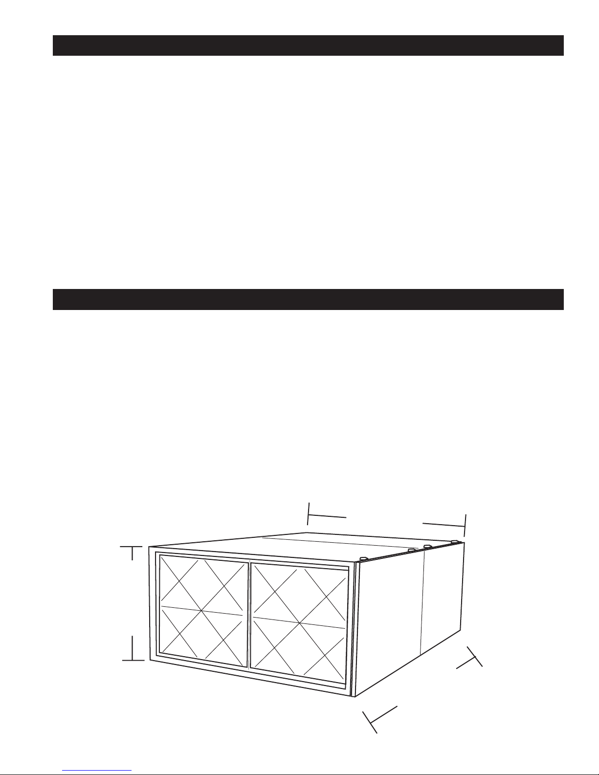
SPECIFICATIONS
Series 3000 Specifications
Dimensions:
Weight:
Motor:
Air Volume:
95.25"L x 51.25"W x 26.25"H
(241.9 x 130.2 x 66.7 cm)
900 - 1200 lbs. (408.2 - 544.3 kg) installed
Add 250 lbs (113.4 kg) for shipping
5 HP, 230/460v, 3 PH, 13 Amps, Class I blower, belt drive, FC.
Optional 7.5 HP TEFC 230/460 VAC, 3 PH, 25 Amps, Class II blower,
belt drive FC, or direct drive BC airfoil. Optional motor starter.
3000 - 4800CFM (85 - 136 CMM) depending on filter configuration.
51.25"
77.25"
26.25"
The Eramco air cleaners should be suspended from the ceiling at a height of 15 feet or less
above the floor. Position units as shown in the following illustrations. If you need additional
installation advise contact the distributor/dealer from whom you purchased the equipment. Call
the factory if the distributor/dealer is not available.
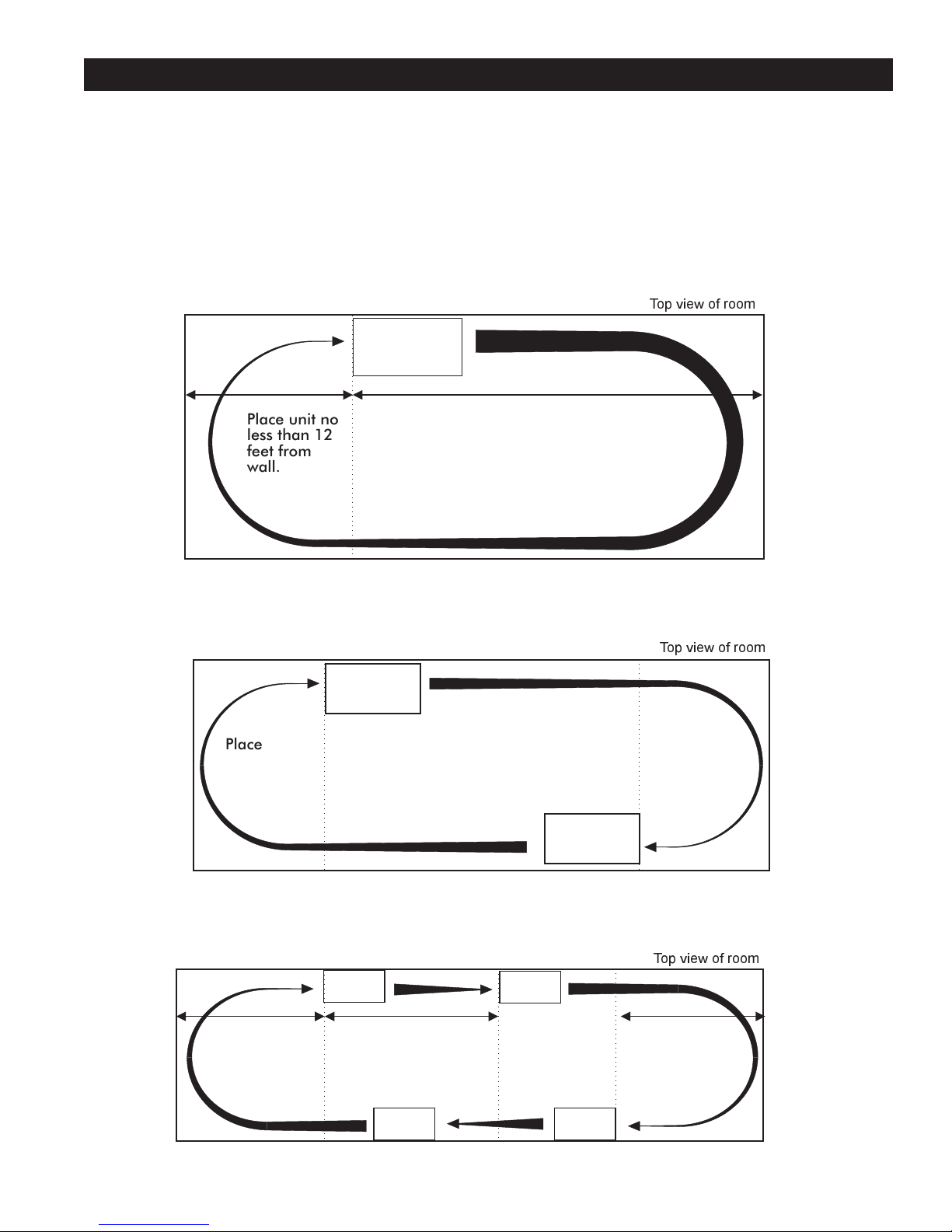
UNIT LOCATION 3
Multi-Unit Configuration
Dual-Unit Configuration
Single-Unit Configuration
Top view of room
Top view of room
Top view of room
Place unit no
less than 12
feet from
wall.
Place unit no
less than 12
feet from
wall.
Place unit no
less than 12
feet from
wall.
No less
than 25%
of room
length.
No less
than 25%
of room
length.
30% of
room
length.
70% of room
length but not
more than 45
feet.
4INSTALLATION
ELECTRICAL
UNPACKING
PREPARATION
Upon receipt, immediately inspect the carton for damage during transit. Signs of rough handling
may indicate internal damage in the air cleaner. Carefully unpack the unit and examine it for
concealed shipping damage. If the unit is damaged, contact the carrier to file a claim.
Carefully read the entire manual before starting installation. Authorities having jurisdiction should
be consulted prior to installation. Permits may be required. If there are no local codes, installation
should conform to the National Electrical Code. The electrical supply, volts, amps, hertz, and
phase, must correspond to that on the unit rating plate. Refer to dimensional drawings for the inlet
and supply dimensions for the duct connections, electrical inlets, and unit clearances before
setting the unit in place. The supply side duct opening at the discharge end of the unit is small
and operates at high velocity. A gradual transition to the larger supply duct should be used and
extra care taken to prevent the accidental dislodging of internal duct insulation in the transition.
Take note of the side clearance required to access blower motor and drive belts, and the space
required to replace the filters. Recommended minimum side clearance is 25" on the door side
and 12" on the power side.
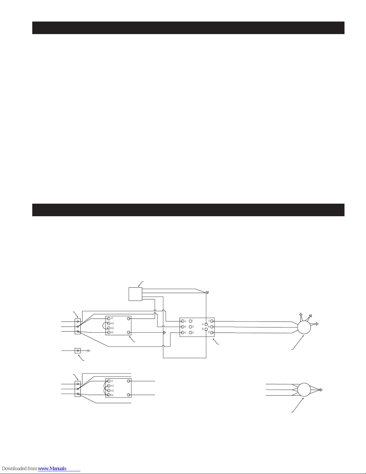
The Series 3000 can be wired for 230 or 460 line voltage. Typical running amps at 230 volts
range from 8.3 to 13 amps depending on the filter configuration and external static load. The
schematic below illustrates the wiring required for each line voltage. The control box will
accommodate conduit from 1/2" to 1 1/4" in each of two bottom knockouts. Field wire the unit with
wire suitable for a 30 amp service and a full load of 13 amps.
BLUE
BLUE
BLUE
240V 3PH
460V 3PH
TERMINAL BLOCK
LINE
LINE
JUMPER
JUMPER
BLUE
GROUND LUG
GROUND
CHASSIS GRND
TERMINAL BLOCK
BLUE
BLUE
BLUE
BLUE
BLUE
YELLOW
YELLOW
BLUE
BLUE
BLUE
BLUE
BLUE
BLUE
TI
TI
T2
T2
T3
T3
T4
T4
T5
T5
T6
T6
T9
T9
T7
T7
T8
T8
24V RELAY SOCKET
460V 3PH 1-SPEED MOTOR
240V 3PH 1-SPEED MOTOR
240/460 V /24V
TRANSFORMER
YELLOW
YELLOW
RED
RED
BROWN
BROWN
BROWN
BLACK
BLACK
CONTROLLER
BLUE
17
8
9
2A
B
3
4
5
6
H1
H1
H2
H2
H3
H3
H4
H4
5INSTALLATION
The unit is shipped in two sections for easier field installation. The blower cabinet comes with a
motor and a belt driven blower. The unit must be mounted with the motor mount base plate down.
The filter cabinet comes with the filter rails and the adsorbent racks pre-installed.
The unit can be lifted into position with the blower housing on the bottom and the filter housing on
top. The unit may also be positioned as two separate pieces. The side doors should remain on
the unit to protect the door gaskets and add rigidity to the door side of the unit. Place the heavier
blower housing in place first and position on the supports and attach to support structure if
required. After the blower housing is in place the filter housing can be positioned and joined.
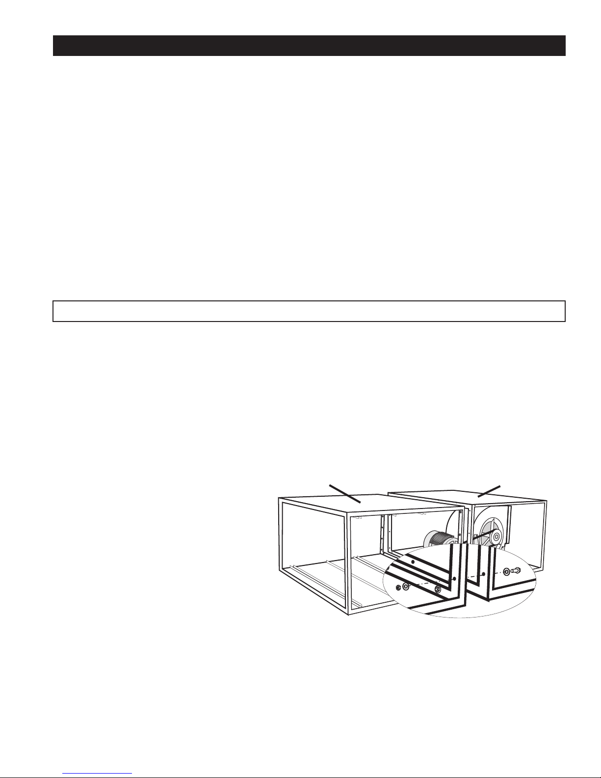
1. Mount the filter cabinet with the
supply end bolted to the return end of
the blower cabinet. Join the two parts
using the 5/16" x 1" bolts, nuts, and
washers supplied with the unit (Fig. 2).
Be careful not to distort or bend the
mating parts. Install one bolt in each
corner and tighten to bring module into
alignment. Install the remaining bolts.
2. Apply the flexible sealant (butyl
caulk) to the outside of the joint to cover
the gasket and to assist in developing
an air and water tight joint.
ASSEMBLY
Verify that the electrical service is the correct voltage, current capacity and phase as listed on the
unit nameplate. Refer to the wiring diagram and verify that the motor and the control transformer
are wired correctly.
Install an electrical disconnect to ensure safe servicing of the unit and emergency shut down.
Check electrical code for location and type of disconnect required.
Size breaker to accommodate the motor start current and the wire size. Field wire the unit using
wire and conduit in compliance with the applicable local electrical code. Verify that the correct
type of four conductor low voltage control wire in accordance with the local electrical code and
ordinances. Standard thermostat wire can be used for most applications. Test the motor for
starting and proper rotation. The blower wheel must rotate toward the cutoff for proper operation
of the unit. Short periods of operation, less than 30 seconds, without filters or with the service
access doors open to verify blower rotation are permitted and will not cause tripping of the
automatic overload protection. If the motor does not rotate in the correct direction (Fig. 4) swap
any two of the main power leads to reverse the rotation.
FILTER CABINET BLOWER CABINET
FASTENER CONFIGURATION
Fig. 2

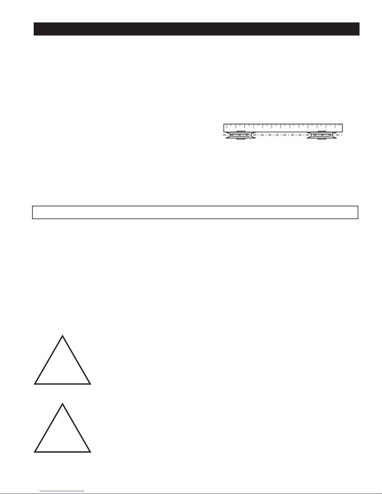
3. Check the blower fan for proper
alignment. The fan should be centered in the
housing. The belt should be tightened so
that you can push down on the belt with one
finger depressing the belt one inch in the
center between the pulleys (Fig. 3).
4. The pulleys should be lined up so that a
straightedge will lay flat against the sides of
both pulleys (Fig. 5). If the pulleys are out of
alignment they must be aligned prior to
operation of the unit. Incorrect alignment will
result in premature belt failure and excessive
pulley wear.
FAN SHAFT POSITION ADJUSTMENT
If the shaft is not properly centered, the fan may scrape against the scroll. To center the assembly,
loosen the Allen set screw on the locking collar of each fan shaft bearing. Slide the shaft into the
proper position and replace the locking collar.
To replace the collar, push it against the
inner race of the bearing, turn the collar in
the direction of the shaft rotation until tight,
then tighten the set screws. Tightening the
locking collar in the direction of the fan
rotation will result in further tightening of the
collar should the set screw work loose.
FAN WHEEL ADJUSTMENT
If the fan is not centered in the scroll and/or
is rubbing against the scroll, it should be
repositioned. Loosen the square head bolt
holding the fan wheel hub to the shaft.
Position the fan wheel in the center of the
fan housing and tighten the locking bolt.
Clearances between the wheel and housing
should be the same on each side.
6INSTALLATION
BELT TENSION
(1" Maximum)
BLOWER ROTATION
Fig. 3
Fig. 4
!Do not change the pulley sizes on the unit without factory
authorization. The motor size and blower RPM are balanced with
the standard filter configuration to provide optimum performance
and protect the motor from overload and permanent damage.
ADJUSTMENTS
FAN ROTATION
Fan rotation is toward the cutoff point or clockwise viewed from the pulley end of the blower shaft
(Fig. 4).
PULLEY ALIGNMENT
Proper pulley alignment is necessary to prevent
excess wear of the fan belt and pulleys. To adjust,
remove the two 1/4" bolts from the tapered hub
bushing. Thread them into the two threaded openings
to separate the hub from the pulley. Move the hub in
the direction necessary to align the pulley. Remove
the bolts and place them through the holes in the hub
and into the threaded holes in the pulley. Take up the
slack and tighten the bolts to relock the pulley to the
shaft. Use the straightedge to check alignment (Fig.
5). Repeat the adjustment process as required.
The unit requires a minimum of six (6) points of support that are three inches square and elevate
the door side three (3) inches from the surface to provide door latch clearance. The mounts should
be positioned at each of the four corners and two to support the joint of the unit halves. Support
beams or pads must be located three (3) inches away from the bottom to allow operation of the
bottom door latches. If 4"x4" timers are used be sure that they are both long enough to support the
weight and oriented so as to transfer the weight of the unit to the underlying support structure. If
attachment to the support structure is required, the floor or back side may be field drilled for bolts
or screws. Seal all penetrations with silicone rubber or butyl rubber to avoid water and air leaks.
Take care to place bolts where they will not interfere with filter insertion or removal. The standard
unit is NOT designed to be stacked two high or mounted vertically. Contact the factory for special
mounting requirements.
7INSTALLATION
PULLEY ALIGNMENT
Fig. 5
MOUNTING
!
!
Take note of the units weight and the maximum safe static load that
the mounting location will support. The blower end of the unit may
be heavier than the filter end. For roof mounting, add the expected
snow and ice load to the unit weight in order to arrive at a safe load
requirement.
Keep loose objects out of the blower and filter housing. Loose
objects pulled into the blower can cause the mechanical failure of
the blower wheel and result in severe injury to persons in the
discharge path.

ROOF MOUNT
The unit should be supported on beams or pads that are high enough so that water on
the roof cannot rise to the bottom of the unit. If 4"x4" timers are used, be sure that they
are both long enough to support the weight and oriented so as to transfer the weight of
the unit to the roof and the underlying support structure. If attachment to the support
structure is required, the floor or back side of the unit may be field drilled for bolts or
screws. Seal all penetrations with silicone rubber or butyl rubber to avoid water and air
leaks. Place bolts or screws where they will not interfere with filter insertion or removal.
Take care to locate the duct work so that the filter and motor are easily serviced. Locate
and shim the support beams or pads so they equally support the load.
PAD MOUNT
The unit should be supported on beams or pads that are high enough that water cannot
rise to the bottom of the unit and damage the filters or the motor. If 4"x4" timbers are
used be sure that they are both long enough to support the weight and oriented so as to
transfer the weight of the unit to the pad. Take care to place the duct work so that the
filters and motor are easily serviced. Locate and shim the support beams or pads so
they equally support the load.
8INSTALLATION

MAINTENANCE 9
Filters must be replaced with filters of the same size, type, and efficiency rating in order to
maintain the performance of the unit. Incorrect filters can lead to premature motor failure and will
void the manufacturer's warranty. Check with the distributor or manufacturer to determine the
exact filter configuration for the specific installation.
Remove the filter cabinet door by unlatching the top and bottom latches and removing the door.
Remove the dirty filters by sliding them out of the open door side. Place the new filters in the
same location, observing the air flow direction.
Adsorbent Filter Tray
The unit is shipped with the adsorbent filters wrapped in a protective film. The protective film must
be removed prior to operation. Remove the filter cabinet door and slide out the adsorbent filter
tray. Remove the screws that hold the end panel in place and remove the end panel. Slide the
individual adsorbent filters from the tray, remove the protective wrap and place the filters back into
the adsorbent filter tray. Replace the end panel and the screws. Repeat the process for the
remaining filters.
!
!
!
Do not operate the unit without the filters in place or with an access
door open as this will place a load on the motor that exceeds its
rating and will damage the motor.
Replace filters only with factory supplied or factory approved filters
to ensure continued performance and continuance of factory
warranty.
Do not operate the unit without a discharge duct or a shield to
protect personnel from the high velocity air discharge. Dirt and other
material can be propelled with sufficient force to cause injury.
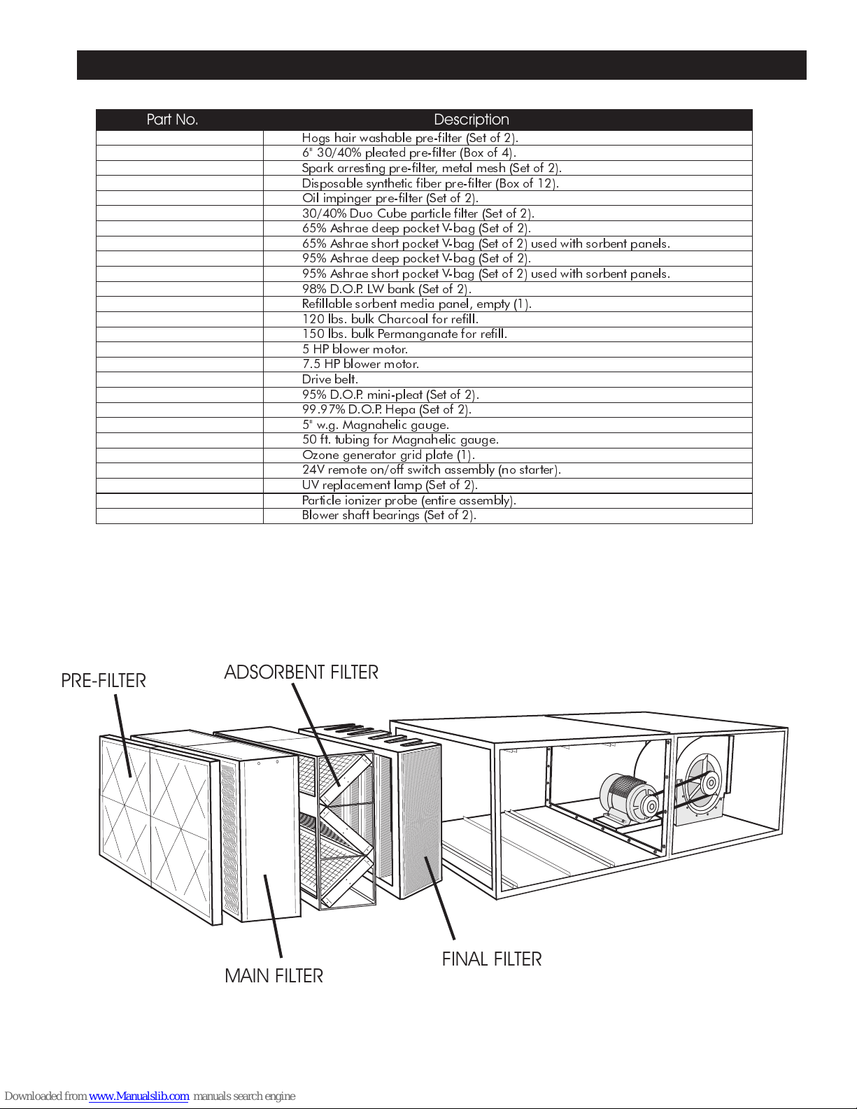
REPLACEMENT PARTS LIST 7
Hogs hair washable pre-filter (Set of 2).
6" 30/40% pleated pre-filter (Box of 4).
Spark arresting pre-filter, metal mesh (Set of 2).
Disposable synthetic fiber pre-filter (Box of 12).
Oil impinger pre-filter (Set of 2).
30/40% Duo Cube particle filter (Set of 2).
65% Ashrae deep pocket V-bag (Set of 2).
65% Ashrae short pocket V-bag (Set of 2) used with sorbent panels.
95% Ashrae deep pocket V-bag (Set of 2).
95% Ashrae short pocket V-bag (Set of 2) used with sorbent panels.
98% D.O.P. LW bank (Set of 2).
Refillable sorbent media panel, empty (1).
120 lbs. bulk Charcoal for refill.
150 lbs. bulk Permanganate for refill.
5 HP blower motor.
7.5 HP blower motor.
Drive belt.
95% D.O.P. mini-pleat (Set of 2).
99.97% D.O.P. Hepa (Set of 2).
5" w.g. Magnahelic gauge.
50 ft. tubing for Magnahelic gauge.
Ozone generator grid plate (1).
24V remote on/off switch assembly (no starter).
UV replacement lamp (Set of 2).
Particle ionizer probe (entire assembly).
Blower shaft bearings (Set of 2).
Part No. Description
PRE-FILTER ADSORBENT FILTER
MAIN FILTER FINAL FILTER
Table of contents
Other Eramco Air Cleaner manuals

Popular Air Cleaner manuals by other brands


Whirlpool
Whirlpool Whispure APMT2001M Specifications

Robur
Robur AD 14 instruction sheet

LG
LG AS601H Series owner's manual

Dometic
Dometic Breathe Easy AU6 installation manual

Pure n Natural Systems
Pure n Natural Systems LA-1000-FM Installation manual and user's guide

Nordic Home Culture
Nordic Home Culture CF-6500 user manual