Foglio di istruzioni Comando Eco
sezione 5
Rev.: D
Cod.: D-LBR755 21MCLSDC023 20/07/2021
7.1.2 Tastiera
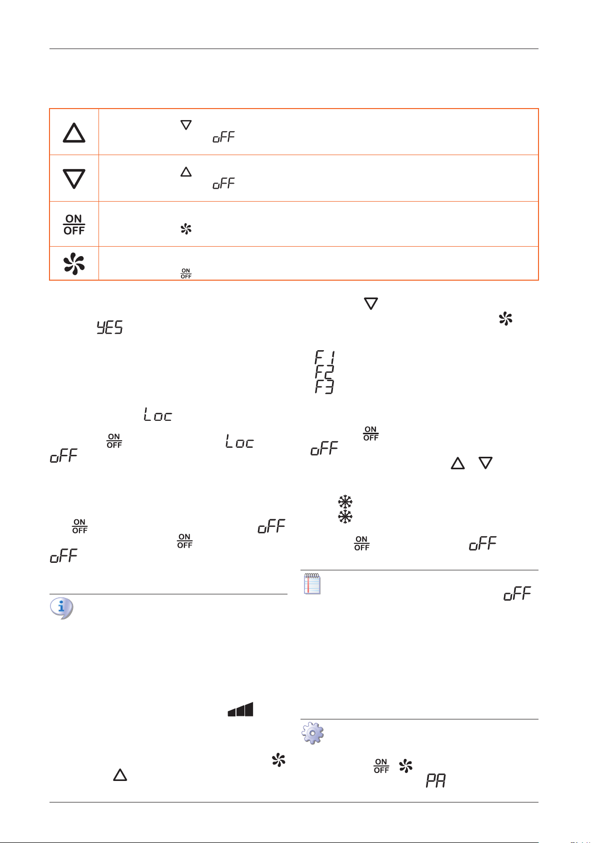
Tabella7.2Tastiera
In programmazione, aumenta i valori a display
Premuto assieme al tasto per più di 2 s diminuisce il contrasto display
Premuto a comando spento (scritta a display) seleziona la modalità di funzionamento all'accensione: sola ventilazione o raresca-
mento
In programmazione, diminuisce i valori a display
Premuto assieme al tasto per più di 2 s aumenta il contrasto display
Premuto a comando spento (scritta a display) seleziona la modalità di funzionamento all'accensione: sola ventilazione o raresca-
mento
In programmazione, svolge la funzione di tasto enter/conferma
Premuto per 1 s consente di accendere/spegnere il comando (e il relativo rarescatore)
Premuto assieme al tasto per più di 2 s consente l’accesso ai parametri del comando
Premuto per più di 3 s a tastiera bloccata consente lo sblocco temporaneo della tastiera
In programmazione, funziona come tasto ESC
Premuto brevemente visualizza la velocità del ventilatore ne permette la modica
Premuto assieme al tasto per più di 2 s consente l’accesso ai parametri del comando
7.1.2.1 Blocco/sblocco tastiera
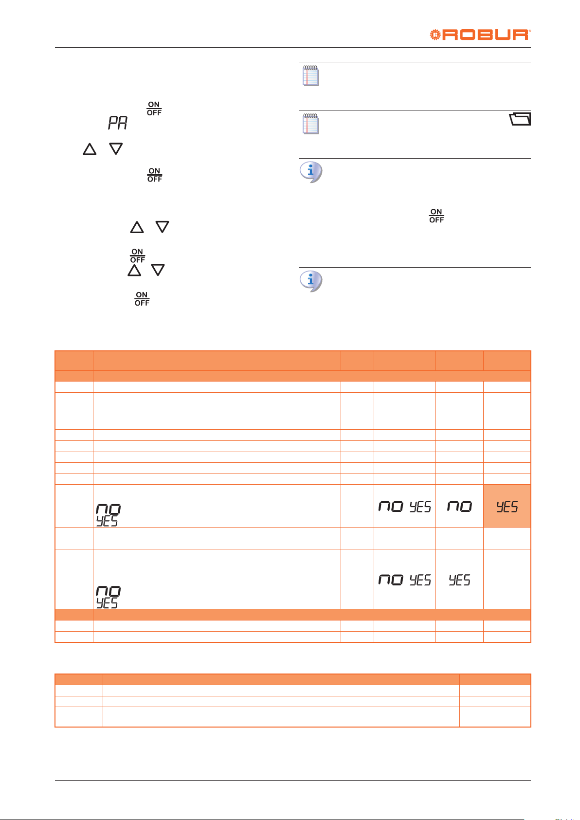
Per bloccare la tastiera è necessario impostare il parametro
HL al valore (Paragrafo 7.5
p.5
).
Con il blocco tastiera inserito le seguenti operazioni non so-
no consentite:
▶
modica/lettura dei parametri
▶
modica della modalità funzionamento
▶
lettura della velocità del ventilatore
Quando la tastiera è bloccata ad ogni pressione sui tasti vie-
ne visualizzata la scritta .
Per sbloccare temporaneamente la tastiera mantenere pre-
muto il tasto no a quando la scritta passa a
. La tastiera ritorna automaticamente nella condizio-
ne di blocco dopo 15 s dall'ultima pressione di un tasto.
7.2 ACCENSIONE E SPEGNIMENTO
Per spegnere il comando e il relativo rarescatore premere il
tasto no a quando il display visualizza la scritta .
Per accenderlo premere il tasto no a quando la scritta
scompare dal display. La modalità di funzionamen-
to all'accensione dipende da quanto impostato a comando
spento (Paragrafo 7.4
p.5
).
Il comando rimane alimentato anche quando è
spento, così come il rarescatore a cui è collegato.
7.3 VISUALIZZAZIONE E MODIFICA DELLA
VELOCITÀ DEL VENTILATORE
Per visualizzare la velocità del ventilatore, a rarescatore ac-
ceso (in modalità rarescamento o sola ventilazione), osser-
vare l'icona della barra a 3 tacche sul display ( ):
▶
1 tacca F1 (velocità minima)
▶
2 tacche F2 (velocità media)
▶
3 tacche F3 (velocità massima)
Per modicare la velocità del ventilatore premere il tasto .
Premere il tasto per incrementare la velocità.
Premere il tasto per diminuire la velocità.
Per uscire e registrare le modiche premere il tasto oppu-
re attendere 10 s senza operare sulla tastiera.
La velocità del ventilatore può assumere tre valori:
▶
velocità minima del ventilatore
▶
velocità media del ventilatore
▶
velocità massima del ventilatore
7.4 MODO FUNZIONAMENTO
Premere il tasto no a quando il display visualizza la scrit-
ta per spegnere il comando e il relativo rarescatore.
A comando spento premere i tasti e per impo-
stare la modalità di funzionamento del rarescatore alla
riaccensione:
▶
icona accesa: modalità rarescamento
▶
icona spenta: modalità solo ventilazione
Per accendere il rarescatore nella modalità selezionata pre-
mere il tasto no a quando la scritta scompare
dal display.
L'impostazione della modalità di funzionamento è
possibile solo a rarescatore spento (scritta a
display).
7.5 PARAMETRI RAFFRESCATORE
I parametri di seguito descritti appartengono alla scheda del
rarescatore ma vengono gestiti tramite il comando in quan-
to il rarescatore non è dotato né di display né di tastiera.
I parametri del rarescatore prevedono tre livelli di accesso,
dettagliati nella Tabella 7.4
p.6
.
Accesso ai parametri ed eventuale inserimento
password
▶
Premere i tasti e per almeno 2 s.
▶
Il display visualizza la scritta .
+39 035 888111 - F +39 035 884165 www.robur.it24040 Verdellino/Zingonia (BG) Italyvia Parigi 4/6 robur@robur.itRobur S.p.A.