Ercolina HB60 User manual

-1-
05/2021 HB60
HB60 Hot Shot Hydraulic Bender
Rotary Draw Bender for Pipe, Tube and Prole Bending
Operator’s Manual
WARNING!
BEFORE USE, BE SURE EVERYONE USING THIS MACHINE READS AND
THOROUGHLY UNDERSTANDS ALL SAFETY AND OPERATING INSTRUCTIONS IN THIS MANUAL
Model Hot Shot HB60___________________ Serial # __________________________

-2- 05/2021HB60
Hot Shot HB60 Hydraulic Rotary Bender
Pipe, tube and prole bending machine
Congratulations on your purchase of an Ercolina® bending machine from CML USA, Inc.
Ercolina® machines are designed and manufactured to deliver years of trouble-free bending
performance. Please take a moment to complete and mail the warranty registration card or
submit the information online at http://ercolina-usa.com/warranty-form/. Doing so validates
machine warranty period and ensures prompt service if needed. Thank you for selecting
products from CML USA, Inc. Ercolina®.
Table of Contents
Important safety instructions........................................................................................................................ 4
Special instructions...................................................................................................................................... 5
1. General notes................................................................................................................................... 6
1.1. Technical data .......................................................................................................................... 6
1.2. The purpose of the user and maintenance manual ................................................................. 7
1.3. List of symbols used ................................................................................................................ 7
1.4. Safety solutions for decreasing risks ....................................................................................... 8
1.5. Personal protective equipment (PPE) ...................................................................................... 9
1.6. Recipients of this document ..................................................................................................... 9
1.7. Storing these Instructions ........................................................................................................ 9
1.8. Marking .................................................................................................................................. 10
2. Packaging....................................................................................................................................... 11
2.1. Packaging ...............................................................................................................................11
2.2. Standard equipment ............................................................................................................... 12
2.3. Reception ............................................................................................................................... 12
2.4. Transport ................................................................................................................................ 12
3. Commissioning.............................................................................................................................. 13
3.1. Workspace ............................................................................................................................. 13
3.2. Environmental parameters ..................................................................................................... 14
3.3. Connecting to the mains ........................................................................................................ 14

-3-
05/2021 HB60
4. Use of the HB60 machine.............................................................................................................. 15
4.1. General overview ................................................................................................................... 15
4.2. Description of the parts .......................................................................................................... 15
4.3. Tools description .................................................................................................................... 17
4.4. Preparing the tube ................................................................................................................. 18
4.5. Controls .................................................................................................................................. 18
4.6. Tool assembly ........................................................................................................................ 19
4.7. Replacing the tank cap .......................................................................................................... 23
4.8. Adjustment of the bending angle ........................................................................................... 24
5. Maintenance ................................................................................................................................... 26
5.1. Routine maintenance ............................................................................................................. 26
6. Notes............................................................................................................................................... 27
Pipe and tube information.......................................................................................................................... 28
Bend formula and conversion tables ......................................................................................................... 29
Minimum distance between bends by center line radius, pipe and tube kits ............................................. 30
Terms and conditions of warranty .............................................................................................................. 31
_____________________________________________________
CML USA Ercolina® reserves the right to make improvements and
modications to design without prior notice.
_____________________________________________________

-4- 05/2021HB60
WARNING!
Important Safety Instructions
When using electric tools, basic safety precautions should always be followed to reduce the risk of re,
shock and personal injury.
1. Keep Work Area Clean
Cluttered areas and benches invite injuries.
2. Consider Work Area Environment
Do not expose power tools to rain.
Do not use the power tools in damp or wet locations.
Keep work area well lit.
Do not use a tool in presence of ammable liquids or gases.
3. Guard Against Electric Shock
Prevent body contact with grounded surfaces. For example; pipes radiators, ranges,
refrigerator enclosures.
4. Keep Children Away
Do not let visitors contact tool or extension cord.
All visitors should be kept away from work area.
5. Store Idle Tools
When not in use, tools should be stored in a dry and high or locked-up place out of
reach of children.
6. Do Not Force Tool
It will do the job better and safer at the rate for which it was intended.
7. Use The Right Tool
Do not force small tool or attachment to do the job of a heavy-duty tool.
Do not use the tool for purpose not intended, for example; do not use a circular saw for
cutting tree limbs or logs.
8. Dress Properly
Do not wear loose clothing or jewelry; they can be caught in moving parts.
Rubber gloves and non-skid footwear are recommended.
9. Use Safety Glasses
Also use face mask or dust mask if operation is dusty.
10. Do Not Abuse Electric Cord
Never yank electrical cord.
Keep electric cord from heat, oil and sharp edges.
11. Do Not Overreach
Maintain proper footing and balance at all times.
12. Maintain Tools With Care
Keep clean for better and safer performance.
Follow instructions for lubricating and changing accessories.
Inspect tool cords periodically and if damaged, have repaired by authorized service facility.
Inspect electrical cords periodically and replace if damaged.
Keep handles dry and clean and free from oil and grease

-5-
05/2021 HB60
13. Disconnect Tools
Disconnect machine from power source when not in use, before servicing and changing
accessories.
14. Remove Adjusting Keys and Wrenches
Form a habit of checking to see that keys and adjusting wrenches are removed from machine
before turning it on.
15. Avoid Unintentional Starting
Always disconnect from power source before moving.
16. Stay Alert
Watch what you are doing. Use common sense, do not operate tool when you are tired.
(Do not use when taking medications that may cause drowsiness.)
17. Check Damaged Parts
Before further use of the machine, guard or other part that is damaged should be carefully
checked to determine that it would operate and perform its intended function.
Check alignment of moving parts, binding of parts, breakage of parts mounting and any
other conditions that may aect its operation. A guard or other part that is damaged should
be properly repaired or replaced by an authorized service center. Do not use this machine
if switches do not turn it on and o. Have defective switches replaced by authorized service
center.
Special Instructions
1. Read and follow operators manual thoroughly. If you require an additional manual please contact
2. Due to size and weight, it is recommended that qualied professionals transport, position and
install the bending machine. Use proper equipment for installation including lift truck safety
straps, chains binders and bars. Machine must be balanced evenly at all times.
3. Never place hands, nger gloves or clothing near rotation machine parts.
4. Always disconnect machine from power source before changing accessories.
5. Always use eye and hearing protection.
6. Never wear loose clothing, gloves or jewelry when working near machine.
7. Stand in a safe position when operating machine.
8. Always wear safety approved steel toe footwear.
9. Make provision for safe handling of heavy and/or awkward materials.
10. Use only proper tooling, keep tooling securely fastened.
11. Keep machine and tooling free and clear of chips and debris.
12. Keep all safety features functioning and working properly.
13. Do not alter or modify machine. Use only OEM approved parts and accessories.

-6- 05/2021HB60
1. General notes
1.1. Technical data
Operating Range
Resistance module cm3 12
Bending capacity (A53 Grade
A) Inch 2” Schedule 40 Pipe
Minimum external diameter Inch ¼”
Minimum bending radius Inch 1.4”
Maximum bending radius Inch 10.7
Maximum bending angle Degrees 210°
Bending direction - Counter-clockwise
Electrical power supply
Power kW 0.75
Voltage V
120V 1ph standard;
220V 1ph or 480V 3ph on
request
Mains frequency Hz 50-60
Dimensions, weight, other data
Maximum length (approxi-
mate) Inch 29” (machine with cabinet)
Maximum width (approximate) Inch 18.5” (machine with cabinet)
Height (approximate) Inch 40” (machine with cabinet)
Weight (approximate) Pound 450 Pounds
Sound pressure level DB <60
Oil volume in the tank L 10

-7-
05/2021 HB60
Hazard
It indicates that a danger is imminent which, if not considered properly, will cause
serious or fatal injuries.
Caution
It indicates that there is a potential danger which, if not considered properly, may
cause serious or fatal injuries.
Warning
It indicates a safety warning which can cause property damage if ignored.
Note
Relevant information for optimal product operation is indicated as notes.
Hazard
It indicates a crushing hazard for upper limbs which may cause serious or fatal
injuries.
Hazard
It indicates a crushing hazard for upper limbs which may cause serious or fatal
injuries.
1.2. The purpose of the user and maintenance manual
This manual provides guidelines and instructions to use the HB60 machine: these do not replace, alter
or supplement any regulation, prescription, decree or law, regardless of it being general or specic, in
force in the place where the machine is installed and used, concerning safety, use and maintenance of
equipment or systems that may be mechanical, electrical, chemical or otherwise. Manual provides
maintenance personnel with recommendations and support but assumes that they are experienced and
generally well-prepared in handling any maintenance issue, regardless of it being mechanical or
electrical.
In this manual you will nd information about:
● Machine use;
● Technical specications;
● Electrical and mechanical parts;
● Handling, installation and assembly operations;
● Adjustments, start-up, stopping, commissioning and decommissioning operations;
● Safety requirements and guidelines on residual risks;
● Routine maintenance requirements;
● Special maintenance requirements;
● Spare parts;
● Tooling and accessories.
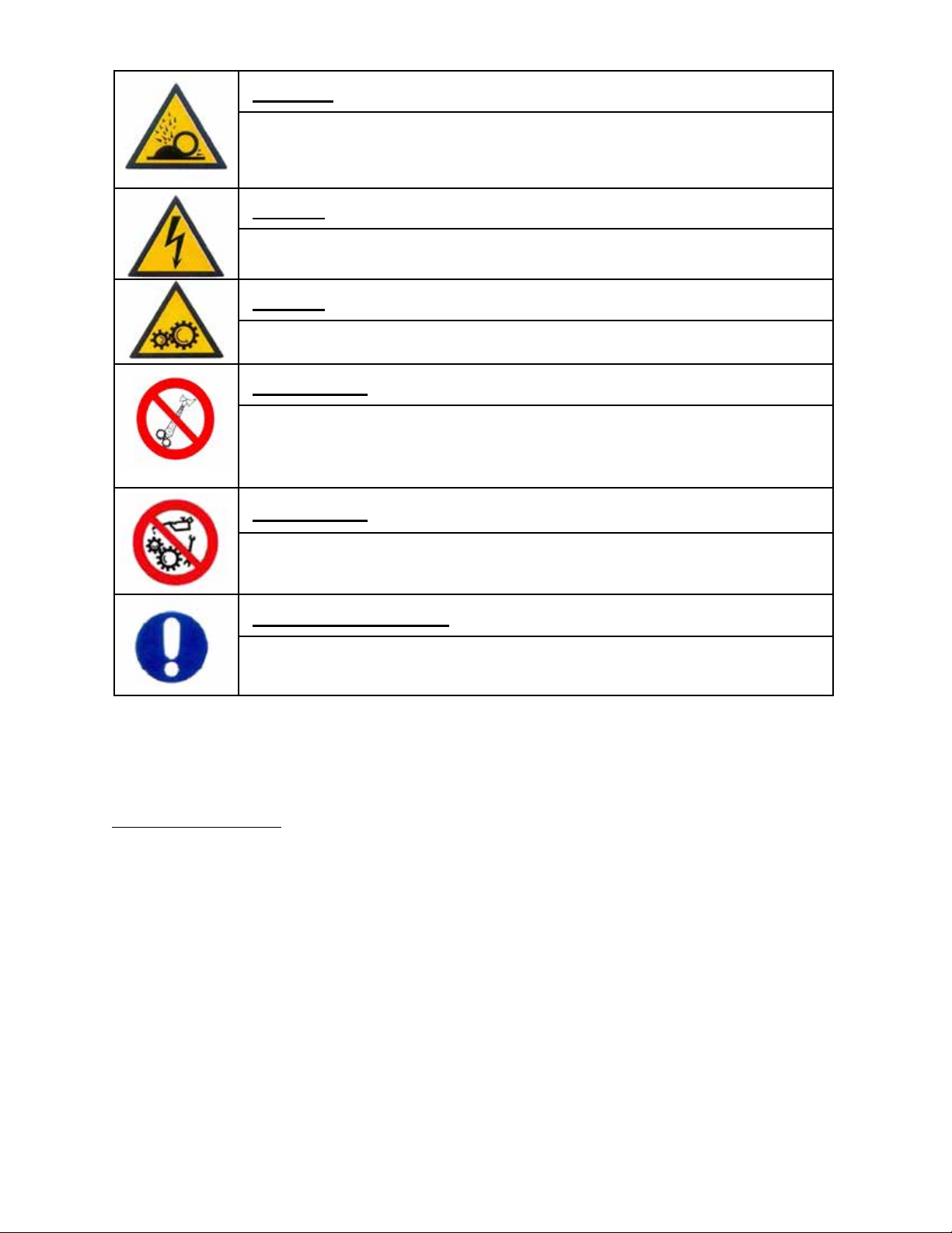
1.3. List of symbols used
-8- 05/2021HB60
Caution
Indicates a risk of being hit by metal fragments, from piece being processed.
Hazard
This indicates the presence of electrical voltage which can lead to serious or fatal
injury.
Hazard
This indicates the presence of moving mechanical parts which can lead to
serious or fatal injury.
Prohibition
This informs the operator not to use unsuitable clothing which can even lead to
serious injury.
Prohibition
It informs the operator not to carry out routine and/or extraordinary interventions
during machine operation that may lead to serious or fatal injuries.
Compulsory action
This indicates mandatory operations to be carried out by the personnel, which
can lead to serious injury if missing.
1.4. Safety solutions for decreasing risks
Machine is equipped with emergency button placed in front position to be easily reached operator. Inter-
rupts power supply and any machine movement.
Risks of electrical nature
The machine control devices are low voltage at 24 Volt.
Electrical components are also encased inside base cabinet and accessible by removing screws securing
cabinet door.

-9-
05/2021 HB60
1.5. Personal protective equipment (PPE)
Always operate with personal protective equipment (PPE). Personnel in charge of installation,
maintenance or operation machine must not wear clothes with loose sleeves, laces, belts, bracelets,
long hair or other items that can be hazardous.
Recommended protective equipment to be worn.
1.6. Recipients of this document
This documentation is specic to HB60 model and intended for all machine installers and users
1.7. Storing these Instructions
All instructions regarding HB60 machine must be stored with machine and always be accessible.
Compulsory action: in the related situations, wear the personal protective
equipment indicated in the table below.
Safety shoes
Use: always
Protective clothing
Use: always
Work gloves
Use: always
Safety goggles
Use: always
Helmet
Use: in the presence of suspended loads
Prohibition: do not wear unsuitable clothing which, for example, may get
stuck in moving parts and result in dangerous situations.

-10- 05/2021HB60
1.8. Marking
● Logo of CML INTERNATIONAL S.p.A. and its references;
● Year of manufacture of the machine;
● Weight of the machine;
● Model of the machine;
● Operating voltage;
● Mains frequency;
● Maximum amperage;
● Power;
● RPM of bending shaft
● Serial number.
Figure 1 - Identication plate
-11-
05/2021 HB60
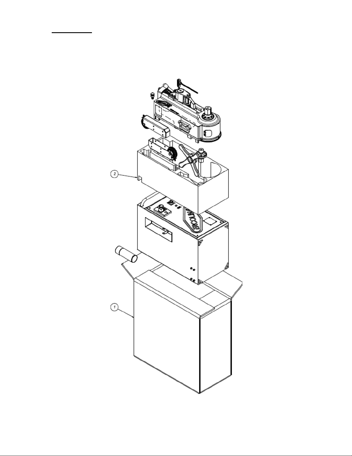
2. Packaging
2.1. Packaging
Figure 2 - Package contents

-12- 05/2021HB60
Figure 3 - Indicating wheels and retractable handle
2.2. Standard equipment
The following are supplied with machine
● Can of spray grease part number P810, intended for lubricating the groove of counter-bending die
● 40 mm and 50 mm hexagonal tooling shafts
● Hand wheel to move the cursor longitudinally
● Pedal control for bend and return function
● Hex key, for opening the cabinet;
● User and maintenance manual.
2.3. Reception
Upon receipt of machine carefully inspect all packaging to verify no damage has occurred during transport
and all standard items are present. Immediately inform the shipping company and CML USA Inc of any
damage or shortage of goods.
2.4. Transport
The HB60 is equipped with two wheels and retractable handle to assist in moving the machine. as shown
in Figure 3.
Attention: Oil reservoir contains oil and is properly sealed prior to shipment. Conrm no oil has
escaped the reservoir during shipment.
Attention: the head can be separated from the cabinet and handled using the specic side
handles.
Attention: while handling the machine, do not use safety ropes and/or chains near hydraulic
pipes and power cables.
Attention: weight distribution of machine can change according to capacity of hydraulic oil
and tooling tted on machine. To facilitate moving and handling packaging labels
indicate lifting area and weight.
Retractable handle
Wheels

-13-
05/2021 HB60
Hazard: it is strictly forbidden to lift the machine with any means other than forklifts, as shown
in Figure 4.
Figure 4 - Incorrect handling
3. Commissioning
3.1. Workspace
The minimum space necessary for using the HB60 machine can be calculated based on the length of
the material to be processed: to obtain it, refer to what is shown in Figure 5. Be very careful to allocate
enough space in order to ensure the materials can be handled near the machine.
Figure 5 - Space necessary for using the HB60 machine
-14- 05/2021HB60
Danger: in the work area only one single operator can be present at one time.
Danger: during the bending phases, the operator must always be in a position opposite the
movement direction during bending. Operator must always be in position to press emergency
stop button.
3.2. Environmental parameters
The HB60 machine was designed to resist corrosion. All of its components, excluding moving ones, are
covered with oven-baked epoxy paint. However, the machine has been designed to be used indoors and
in environments away from the sea coast: contact the Customer Service of the Manufacturer for installa-
tions other than those mentioned above. The recommended environmental conditions are: Temperature:
5°C - 30°C. with Humidity: 40% - 75%. If the temperature of the installation area differs from the indicated
range, the recommended hydraulic oil may no longer be suitable to guarantee machine performance: con-
tact the manufacturer’s customer service for advice.
3.3. Connecting to the mains
Danger: HB60 machine must be powered with alternating current (AC) at the indicated
frequency and voltage.
Attention: manufacturer is not liable for faults caused by an incorrect electrical
connection implemented by the user.
Attention: Connection to power mains must be made by qualied personnel.
Danger: Electrical panel must be opened by qualied personnel Opening and
tampering with electrical components can jeopardize operator safety and
correct machine operation.
Attention: Make sure power phasing is correct.
Danger: Switch main power to o and disconnect from power source before accessing
electrical compartment of machine make sure that it is switched.

-15-
05/2021 HB60
4. Use of the HB60 machine
4.1. General overview
The HB60 bends pipe, tube and profiles within its capacity. Refer to Ercolina catalog for proper tooling
selection. Bending results depends on:
● Material type and grade
● Conditions of material when supplied
● Capability of the operator.
The same operation completed on different materials may have completely different results. To obtain
best results ensure material to be processed is guaranteed in its chemical composition and has received
adequate stretching treatment. Verify that section dimensions are within supply tolerance.
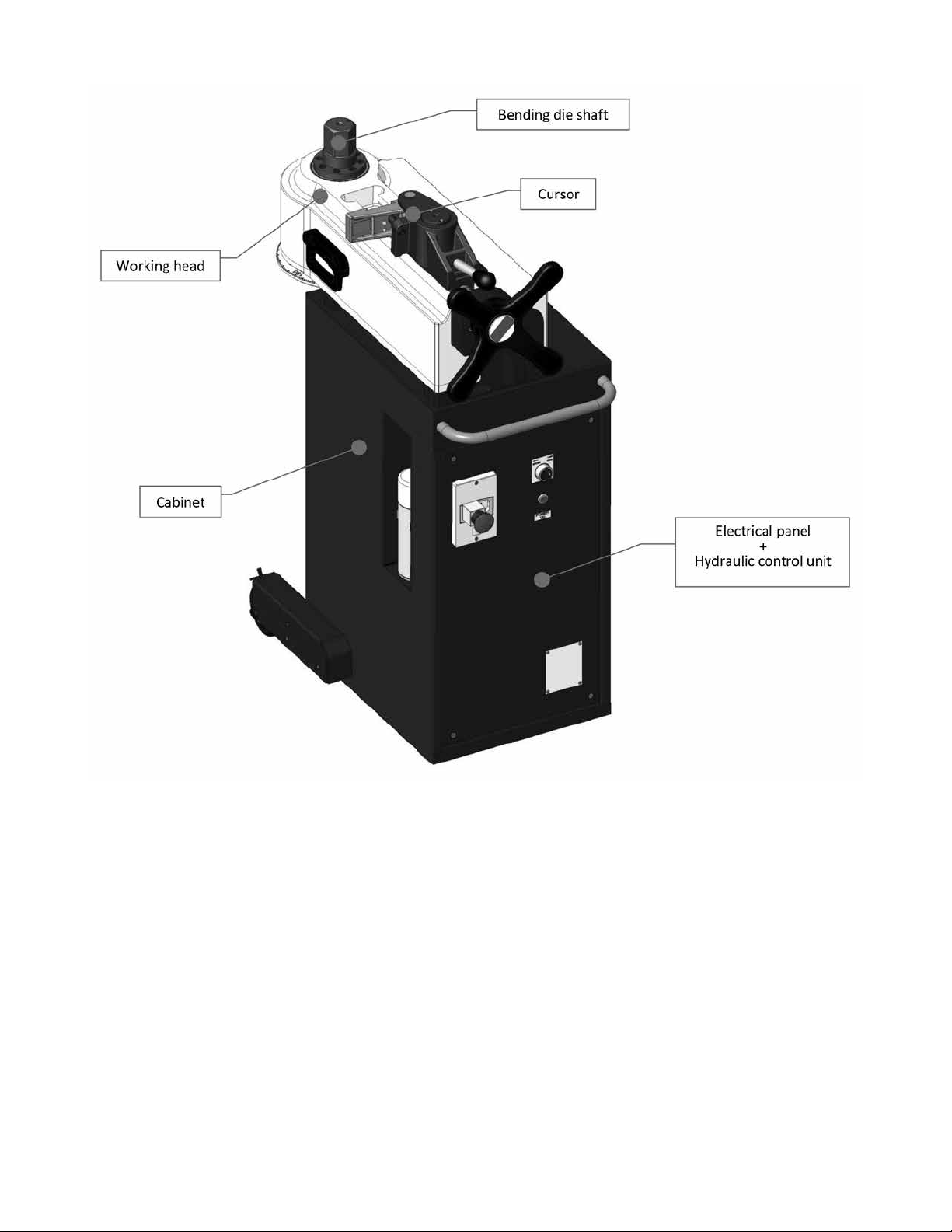
4.2. Description of the parts
The HB60 machine consists of the following parts:
● Cabinet
Supports machine and house electrical, hydraulic, mechanical and protective parts are assembled
on it.
● Work head
Is main body of machine where tooling shaft, bending center former and counterbending die are
located.
● Cursor
Handwheel adjusts position of the counterbending die axis during machine set-up and allows the
tube to be released after bending.
● Bending die shaft
Component retains bending center former
● Hydraulic control unit
Supplies hydraulic force
● Electrical panel
Components related to electrical power supply of machine. The electrical panel is inserted within
the cabinet: Construction details are found in wiring diagrams.
● Foot Pedal
Controls bend and return functions and returns machine to starting initial position.
-16- 05/2021HB60
Figure 6 - Constructive elements of the machine
-17-
05/2021 HB60
4.3. Tools description
Refer to manual for machine capacity
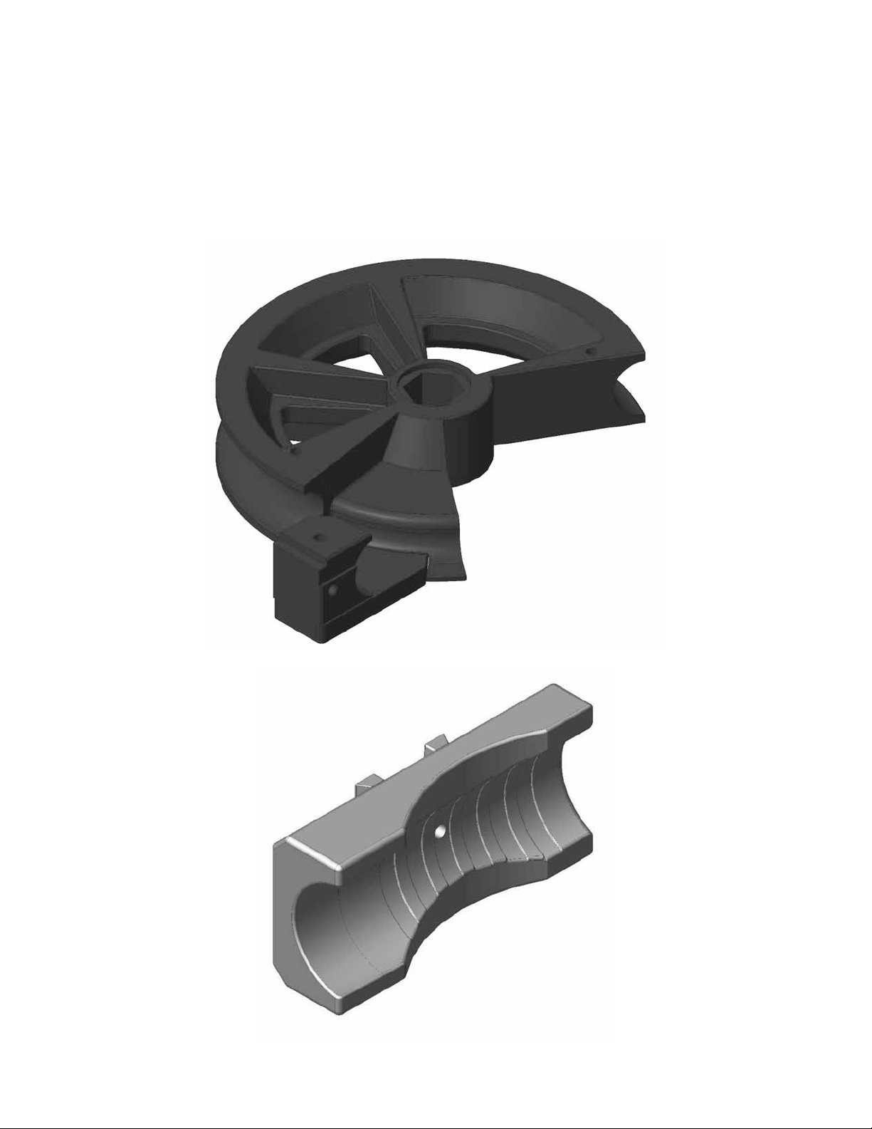
Tooling components: Shown in Figure 7, 8, 9:
● Bending Die
● Counterbending die
● Hexagonal shaft 40 and 50 MM are supplied to accommodate the machine capacity
Figure 7 - Center Former Bending Die
Figure 8 - Counterbending Die
-18- 05/2021HB60
4.4. Preparing the tube
● Verify that the dimensions of the tube/profile match the tooling mounted on machine;
● Tube dimensions and type of material are correct for tooling and bending
● Deburr inner and outer edges of the material to be bent
● Tooling gripping area clean and degreased.
4.5. Controls
The HB60 machine also has:
● General power supply switch;
● Emergency button;
● Start button;
● Speed selector;
● Foot pedal.
General power supply switch
To power machine, rotate selector from “OFF - 0” position to “ON - 1” position. This operation sends
electrical power to all electrical and safety devices. Electrical motor of the hydraulic control unit will only
start after pressing the reset button.
Emergency stop button
Pressing the emergency stop button will stop all movement. The emergency stop button is fitted with an
automatic locking system once pressed remains in position. The machine cannot be reset in this phase.
The emergency button is released by rotating it in the direction indicated by the embossed arrow.
Start button
Release emergency stop button by rotating it in the direction indicated by arrow, press the start button to
restart the machine and restart operation.
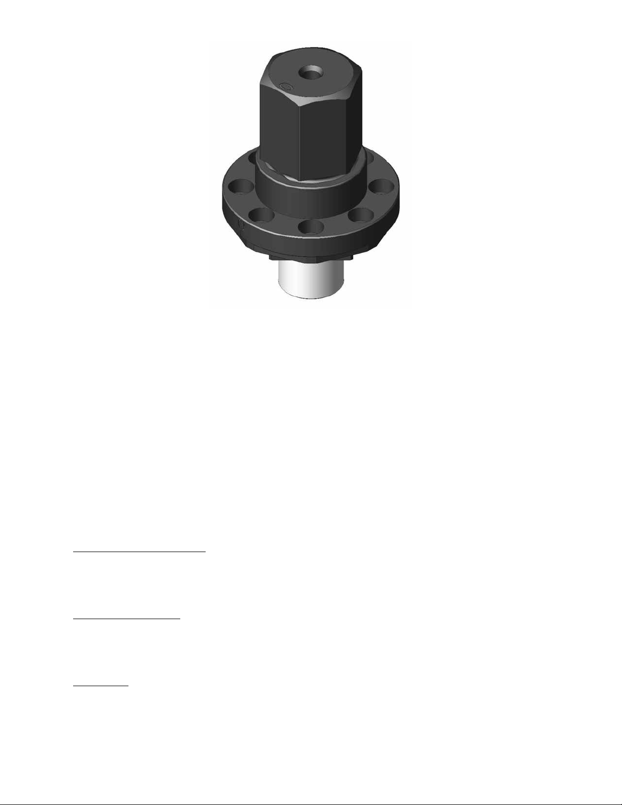
Figure 9 - Hexagonal Shaft

-19-
05/2021 HB60
Speed selector
Machines with single phase power supply are equipped with an inverter, there is also a speed selector
present. Selector rotation changes speed of the motor - speed 1 allows the machine to deliver maximum
bending torque; speed 2 increases machine productivity, however it does not supply maximum machine
torque.
Foot Pedal
Initiate bend or return function.
4.6. Tool assembly
Attention: before assembling the tools, make sure machine is not powered rotate main switch
to “0” position.
Attention: when assembling any tool (shaft, bending die, counterbending die) pay careful
attention to the risk of crushing ngers between the parts.
Assembling the bending die shaft
The machine is supplied with two hexagons drive shafts
● Shaft with hex key 40;
● Shaft with hex key 50.
The choice of the shaft depends on the type of bending die being used.
The assembly procedure is the same for both shafts:
● Insert shaft and the supplied screws.
shaft is designed in such a way there is only one position between parts.
“0” marks are found on both the bending die shaft and the machine. These must always be
aligned machine in the start or zero position.

-20- 05/2021HB60
Table of contents
Other Ercolina Construction Equipment manuals

Popular Construction Equipment manuals by other brands


Case
Case 650M Service manual

Prostor
Prostor FIX-GA-P6 Series Installation instruction

probst
probst FTZ-UNI-25 operating instructions

KRAUSE
KRAUSE ClimTec 710116C0 Assembly instructions and user's manual

JLG
JLG R1532i Operation and safety manual

BUFFALO TURBINE
BUFFALO TURBINE BT-G12DB Original instructions and parts manual