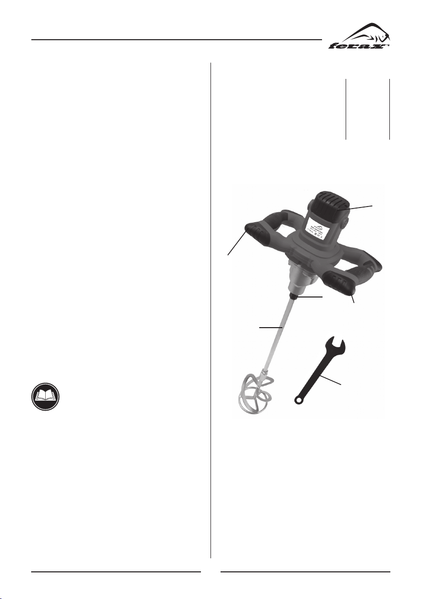
Ferax BCM-1350 User manual

lnstruktionsbok Manual
Code no. 19694-1702

21
ENGLISH
Original instructions
CONTENTS
1. Introduction..........................................21
2. Technical specification.........................21
3. Features ................................................21
4. Safety instructions................................22
5 Assembly..............................................22
6 Use .......................................................22
7 Electronic motor control ......................23
7.1 Starting current limiting.......................23
7.2 No load speed reduction ........................23
7.3 Speed pre-selection ..............................23
7.4 Constant electronics.............................23
7.5 Electronic overload protection.............23
7.6 Temperature-dependant overload
protection .............................................23
8 Service & maintenance ........................23
8.1 Maintenance.........................................23
8.2 Cleaning................................................24
8.3 Faults....................................................24
8.4 Environment..........................................24
8.5 Warranty................................................24
Spare parts list...............................................37
EC conformity declaration............................38
1. INTRODUCTION
Always read the instruction for elec-
trical products carefully before use. It
will help you understand your product
more easily and avoid unnecessary risks.Keep
this instruction manual in a safe place for
future use.
The machine is only intended for mixing
concrete, cement or paint. Improper use may
damage the tool.
2.
TECHNICAL SPECIFICATION
Voltage ....................................... V 230
Frequency................................. Hz 50
Power input............................... W 1350
No load speed ...................... r/min 0- 760
Whisk Ø ..................................mm 120
Weight....................................... kg 5.6
3. FEATURES
2
3
4
1
5
6
Fig. 1
1. Switch
2. Speed control wheel
3. Tool mount
4. Ventilation apertures
5. Wrench
6. Whisk

22
4. SAFETY INSTRUCTIONS
Explanation of symbols
In this manual and/or on the machine the fol-
lowing symbols are used:
In accordance with essential applica-
ble safety standards of European
directives.
Class II machine - Double insulation -
You don’t need any earthed plug.
Denotes risk of personal injury, loss
of life or damage to the tool in case of
nonobservance of the instructions in
this manual.
Indicates electrical shock hazard.
Faulty and/or discarded electrical or
electronic apparatus have to be col-
lected at the appropriate recycling
locations.
Variable speed control
Immediately unplug the plug from the
mains electricity in the case that the
cord gets damaged and during main-
tenance.
Always use ear protection.
Sound power level
Specific safety instructions
• Thetoolshouldnotbeoperatedindamp,wet
premises; during a rain, fog and snow in the
open field, and in environment with a risk of
explosion.
• The switch should be in “OFF” position
before putting the plug in the mains socket.
• For long hair, wear hair protection. Work
only with closely fitting clothes.
• Secure the vessel with the mixed substance
against moving on the floor.
• Always direct backwards the flexible lead
from the tool. The flexible lead should not be
exerted by tensile stress and should not lie on
or pass over sharp edges.
• Usethesupplementaryhandle.
• Considerpossiblereactiontorque.
• Wearearandeyeprotection.
5. ASSEMBLY
Placing a whisk
Remove the plug from the mains
before placing a whisk.
Use only whisks conform the specified dia-
meter.
• Screwthewhiskwithtread(M14)asfaras
possible in the tool.
• Tightenthewhiskproperlywithanopen-end
wrench.
6. USE
Improper use may damage the instrument.
Observe therefore these instructions:
• Useatooluptothespecifieddiameter.
• Load the tool in such a way that the speed
would not drop considerably or that it would
stop.
Check if the data on the rating plate correspond
with the actual mains voltage. Instrument sche-
duled for 230V can be plugged to 220V/240V
mains.

23
The ON/OFF switch
• Toswitchonthetool,pressandholdtheon/
offswitch(1).
• Ifyoureleasetheon/offswitch,thetoolwill
be switched off.
7. ELECTRONIC MOTOR
CONTROL
7.1 Starting current limiting
The electronically controlled smooth start takes
care that the machine starts without jerk. In this
manner, the splashing of thin liquid materials
is prevent at the same time when switching on
the machine.
As a result of the machine’s reduced starting
current, a 16 A fuse is sufficient.
7.2 No load speed reduction
The electronic control reduces the no-load
speed of the machine which results in reduced
noise and wear of motor and gear.
7.3 Speed pre-selection
With the speed control (2) the speed can be
continuously pre-selected: the necessary speed
is dependent on the type of material to be
mixed. It is recommended that it be confirmed
with a practical trial.
7.4 Constant electronics
The constant electronics keeps the speed bet-
ween no-load and load nearly constant and
ensures uniform mixing of the materials.
7.5 Electronic overload protection
In case that the machine is extremely overloa-
ded, an electronic overload protection protects
the motor from damage. In this case, the motor
stops and restarts only after the feeding pres-
sure is reduced.
7.6 Temperature-dependant overload
protection
To protect the motor from overheating at
extreme permanent load, it is switched off by
the protective electronic system when a critical
temperature is reached.
After a cooling-down period of approx. 3 - 5
min., de machine is again ready for use and can
be fully loaded.
When the machine is warmed by use, the tem-
perature-dependent overload protection reacts
earlier as a result.
8. SERVICE & MAINTENANCE
8.1 Maintenance
Make sure that the plug is removed
from the mains when carrying out
maintenance work on the motor.
The machines have been designed to operate
over a long period of time with a minimum of
maintenance. Continuous satisfactory opera-
tion depends upon proper machine care and
regular cleaning.
• The ventilating slots on the motor casing
should be cleaned out from time to time.
• Whenthecarbon brushesare wornout,the
machine switches itself off. The machine
must then be sent to customer service for
maintenance.
• After100hours:checkcarbonbrushes
• After200hours:renewthegreasefillingin
the gearbox
To verify the protective insulation
remains intact, the machine must be
subjected to a technical safety test
afterwards. For this reason, this main-
tenance must be performed exclusi-
vely by a professional electro-work-
shop.

24
8.2 Cleaning
Regularly clean the machine housing with a
soft cloth, preferably after each use. Keep the
ventilation slots free from dust and dirt. If the
dirt does not come off use a soft cloth moiste-
ned with soapy water. Never use solvents such
as petrol, alcohol, ammonia water, etc. These
solvents may damage the plastic parts.
8.3 Faults
Should a fault occur, e.g. after wear of a part,
please contact the service address on the war-
ranty card. In the back of this manual you find
an exploded view showing the parts that can
be ordered.
8.4 Environment
To prevent damage during transport, the app-
liance is delivered in a solid packaging which
consists largely of reusable material. Therefore
please make use of options for recycling the
packaging.
Faulty and/or discarded electrical or
electronic apparatus have to be col-
lected at the appropriate recycling
locations.
8.5 Warranty
The guarantee conditions can be found on the
separately enclosed guarantee card.

37
BCM-1350 DIAGRAM

38
BCM-1350 PART LIST
No. Description Specication Qty
1 Screw ST3.9× 13 18
2 Rear cover 1
3 Carbon brush cover 2
4 Brush 2
5 Brushholder 2
6 Housing 1
7 Stator 1
8 Screw ST4.8× 55 6
9 Upper handle 1
10 Speed control 1
11 Runner corner 4
12 Down handle 1
13 Bearingholder 1
14 Bearing 608 1
15 Rotor 1
16 Screw M4× 16 3
17 Bearing 6001 1
18 Wool ring 1
19 Middle cover 1
20 Corduray 1
21 Oil washer 1
22 Oil port cover 1
23 Flat washer 3 4
24 Spring washer 3 4
No. Description Specication Qty
25 Screw M3× 10 4
26 Oil cover 21× 26× 5 1
27 Cord 1
28 Sheath 1
29 Gear box 1
30 Press board 1
31 Pin 4h 8× 8 1
32 Capacitor 1
33 Switch 1
34 Bearing 628/8 1
35 Third initiative gear 1
36 Third initiative Spindle 1
37 Second driven gear 1
38 Biggear 1
39 Circlip 15 1
40 Bearing HK1010 1
41 Circlip 17 1
42 Circlip 35 1
43 Circlip 10 1
44 Bearing 6003 1
45 First driven gear 1
46 Second driven gear 1
47 Spindle 1

�TM
ARETE S
UPP
LIES S
.
L
.
www.aretesupplies.co
m
Paint-/ cement mixer
BCM-1350
Other manuals for BCM-1350
1
This manual suits for next models
1
Table of contents
Other Ferax Construction Equipment manuals
Popular Construction Equipment manuals by other brands

Dynapac
Dynapac LP 650 operation & maintenance

Ammann
Ammann ASC 110 Workshop manual

JLG
JLG X13JP-X370AJ Service and maintenance manual

Hilti
Hilti CP 660 Instructions for use

stellar labs
stellar labs CDT 5521 owner's manual

Worldwide Construction And Forestry Division
Worldwide Construction And Forestry Division 450J Repair manual