Smith SPS10 User manual
SPS10 Gas
Multi-Use Surface Preparator
User Manual
(954) 941-9744
www.SMITHMFG.com
MANUFACTURING
Cutters / Removers / Parts / Support
1-800-653-9311
www.SmithMfg.com
Phone: 954-941-9744 • Fax: 954-545-0348
SMITH Manufacturing 1-954-941-9744 www.SmithMfg.com
SPS10
VERSION 11/2016
Gas
SMITH Manufacturing 1-954-941-9744 www.SmithMfg.com
INTRODUCTION
2
Congratulations on purchasing the
SPS10™ Surface Preparator from
SMITH Mfg. Company.
Your machine will:
• Clean surfaces impacted by grease, oil,
plastics, tars, resins, tile adhesives, ice and
more
• Plane or mill asphalt and concrete surfaces
• Remove high spots in curbs and gutters
• Eliminate trip-hazards on concrete sidewalks
• Mill areas for rumble strips
• Clean out cracks and joints
• Create anti-slip patterns in walkways and barns
• Prepare surfaces for new coating applications
• Groove-inlay asphalt for striping
• Permanently remove all road and surface
coatings to include:
epoxy, urethane, thermoplastic, paint,
glue-backed tapes and more...
BEFORE START-UP,
READ THIS..
Please read all operating instructions, including
the provided engine manual and be completely
familiar with your equipment before operating.
When in doubt, please contact SMITH
Manufacturing Customer Service for operational
details. This Owner’s Manual will guide you
through the removal process, from start to nish,
and show you how to care for your machine.
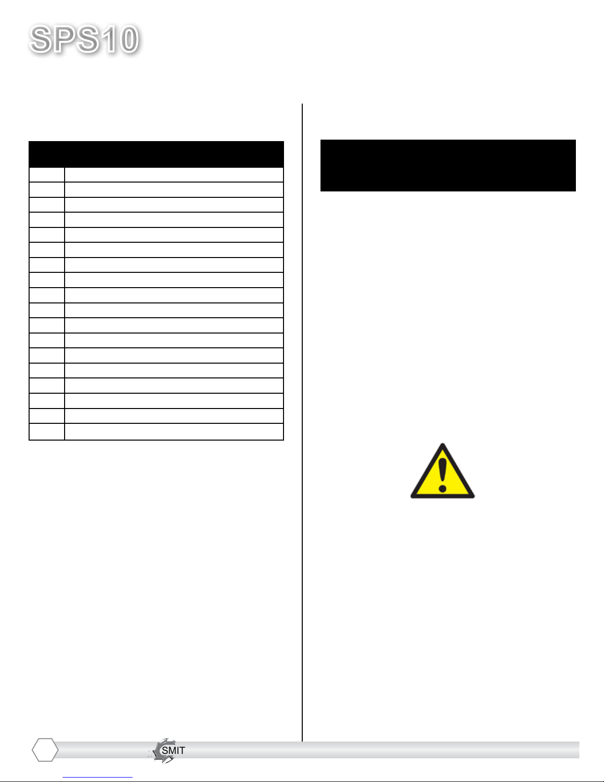
Page Contents
2Index / Introduction
3Safety Guidelines
4Your SPS10 Surface Preparator
5Handle Adjustment Instructions
6Machine Start-Up
7Substrate Removal
8Storage, Ordering, and Warranty Claims
9Troubleshooting
10 Maintenance Check List
11 Drum Replacement
12-14 Belt Replacement and Alignment
15-16 Bearing Replacement
17-24 Optional Equipment
25-26 Drum Options
27-28 Maintenance Log
29 Limited Equipment Warranty
30 Warranty Activation
INDEX

SMITH Manufacturing 1-954-941-9744 www.SmithMfg.com
SMITH Manufacturing 1-954-941-9744 www.SmithMfg.com
VERSION 11/2016
SPS10
Gas
3
UNCRATING EQUIPMENT
When you uncrate your equipment, make certain
that the machine has not been damaged and
that all fasteners and guards are properly
tightened.
Your machine may not have been shipped
assembled with cutters and other accessories.
Assembly may be required.
REMEMBER: Only authorized, experienced and
properly trained personnel should operate this
equipment. Operating personnel should
practice safety at all times and wear protective
gear (gloves, goggles, safety vests, ear plugs,
steel-toe shoes, etc.)
• Always wear protective equipment, including
ear protection and goggles.
• Never wear baggy or loose tting clothing that
can be caught on controls or moving parts.
• The surface preparator can emit ying
particles and debris during operation. Never
operate the machine near bystanders, animals
or children.
• Check uid levels and get acquainted with
the controls, engine kill switch and other safety
controls (pg. 5).
• Do not operate the machine in an explosive
atmosphere, near combustible materials, or
when gas fumes may not be properly dispersed.
• Repair any fuel leaks immediately and remove
accumulated dust frequently from the air lter
system.
• Never leave the machine unattended when
running, and you must hold onto the handle with
two hands when the cutter drum is engaged.
• Avoid contact with the mufer when the engine
is hot, as it may cause severe burns.
• When using a vacuum system, avoid hose
contact with the mufer.
• Ensure that all guards are in place before the
machine is operated, since rotating and moving
parts will cause injury upon contact.
• Make sure that the engine is shut down and
the spark plug is disconnected
before servicing.
Incorrect use of the surface preparator can
result in property damage, personal injury,
or death. Be sure to read and follow all
directions and precautions as outlined in
this manual.
SAFETY GUIDELINES
SMITH Manufacturing 1-954-941-9744 www.SmithMfg.com
SPS10
VERSION 11/2016
Gas
SMITH Manufacturing 1-954-941-9744 www.SmithMfg.com
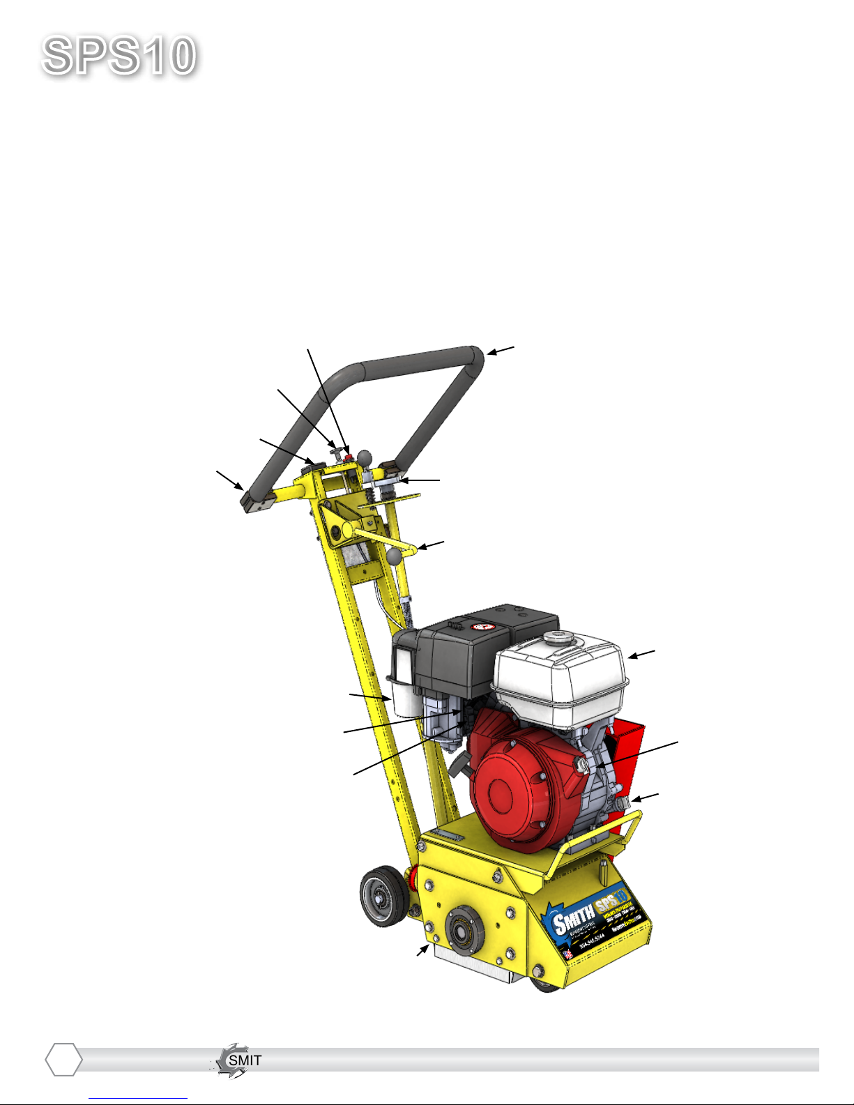
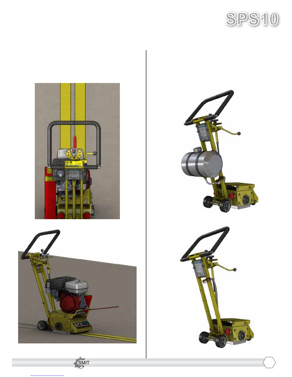
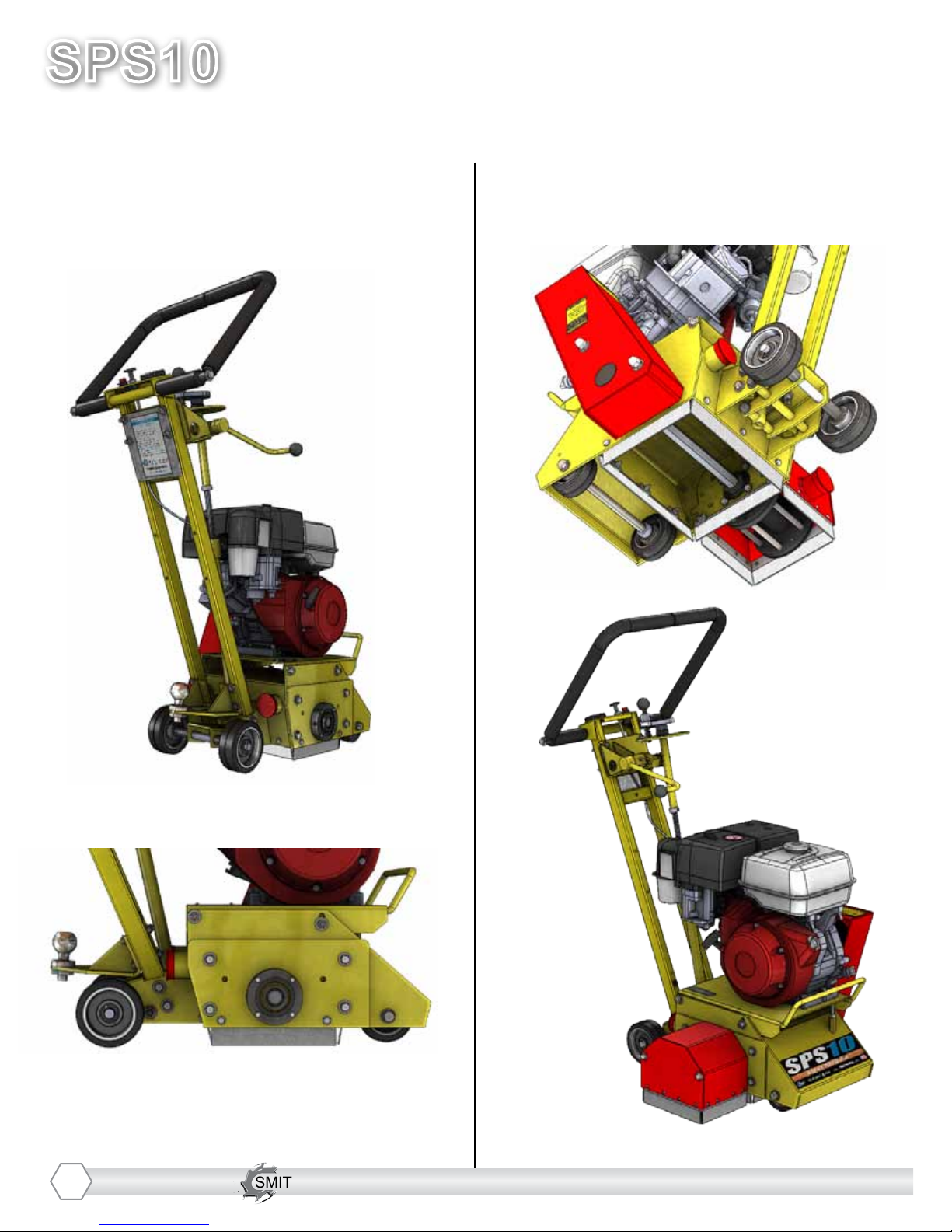
YOUR SPS10TM SURFACE PREPARATOR
Please take time to familiarize yourself with the SPS10™’s
controls, as well as some of the features of your new machine.
Read the engine manual before preparing the engine for starting.
Adjustable Handlebar
Handlebar Adjustment Bolts
Optional Engine Meter
Throttle
Corded “Engine Kill” Button
Fine Adjustment Hand Wheel
Cam Lever
Cyclone Air Cleaner
Oil Dipstick
Engine Shut-Off
Gas Tank
Removable Side Plate
Choke
Fuel Supply Lever
4
SMITH Manufacturing 1-954-941-9744 www.SmithMfg.com
SMITH Manufacturing 1-954-941-9744 www.SmithMfg.com
VERSION 11/2016
SPS10
Gas
5
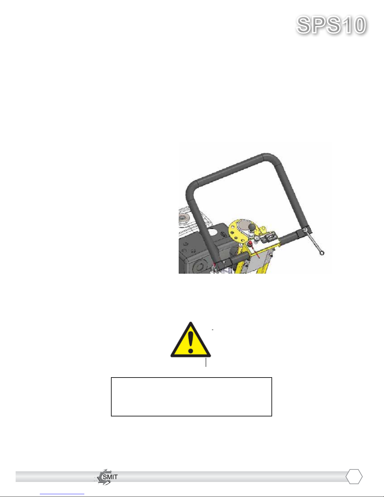
The handlebars are equipped with a high-density vibration suppression material to minimize
operator fatigue and increase comfort level when operating equipment.
To adjust the handlebars to a new position for different height operators please follow these steps:
• Using a 9/16” (14mm) wrench or
socket, loosen the bolts on both
sides of the handlebars until the
handlebar moves freely. Take
care not to over-loosen the bolts
to keep them from falling out.
• Stand behind the machine and
lightly tap the handlebar to the
desired position
• Re-tighten the bolts to lock the
handlebars in the new position.
Never operate with handlebars loose.
The bolts must be fastened tightly assuring
the handle is locked into position.
HANDLE BAR ADJUSTMENT

SMITH Manufacturing 1-954-941-9744 www.SmithMfg.com
SPS10
VERSION 11/2016
Gas
SMITH Manufacturing 1-954-941-9744 www.SmithMfg.com
MACHINE START-UP
Do not start machine while drum is in
contact with the ground. Doing so can
cause the operator to lose control of the
machine, resulting in property damage
and/or personal injury.
NOTE: Do not attempt to raise or lower the cam
lever by force. If it does not move effortlessly,
raise or lower the hand wheel until the cam lever
can be adjusted. Open the fuel cock on the
carburetor and then place the throttle lever at the
“Fast Idle” position. Start the engine, open choke
slightly to prevent ooding. Move throttle control
to open or run position when engine is warmed
up. Increase throttle to maximum operating
position (approx. 2800RPM) and close choke.
Before substrate removal, test run the drum
with cutters not touching the surface. If there is
excessive vibration, you need to re-balance the
cutter set-up, check bearing condition, and/or
make sure that the drive shaft is secured.
Corded “Engine Kill” Button (not available
on electric motor): In the event of a
malfunction or an accident (such as the
machine operator falling or losing footing), the
SPS10 is equipped with a corded “Engine Kill”
Button. Attach the end of the cord to the opera-
tor’s belt or wrist, and snap the clip into place
on the stop switch by raising the top of the
Engine Kill Button and inserting the clip into the
gap. If the operator becomes distanced too far
from the machine, the cord will detach from the
stop switch, and the machine will stop running.
Attatch to
operator
*NOTE: the Engine will not start without the
Corded Engine Kill’s clip securely in place.
CAUTION: The machine will still move with
the engine off.
IF THE ENGINE DOES NOT
START
1) Check Engine for proper gas and oil levels
(refer to Engine manual)
2) Check spark plug. Make sure the socket
areas are clean and clear of debris, and that
the proper gap is set. (Replace if needed).
3) Check Brown Electrical clip hanging on the
front of the engine and ensure that the
electrical wires are making contact within the
clip.
4) Turn the On/Off switch, on the front of the
Engine, to “On”.
5) Check Corded Engine Kill Button’s
Connections:
a) Make sure the Corded Safety Stop “C”
Connector is dipped properly.
b) Try switching the connection to the
opposite post (From letter “C” to letter “M”,
for example).
6) Engine may have tilted backwards. If so,
allow oil to drain after removing spark plug and
pulling starter cord several times.
*Engine repair and engine warranty
issues are handled directly
by your local engine service center.
6

SMITH Manufacturing 1-954-941-9744 www.SmithMfg.com
SMITH Manufacturing 1-954-941-9744 www.SmithMfg.com
VERSION 11/2016
SPS10
Gas
7
SUBSTRATE REMOVAL
Warning: Should you desire to tilt the
machine, always tilt forward. Tilting the
machine backwards at any time will ood
the spark plug with oil and may cause
damage to your engine!
Adjust the height of the cutter drum with
the Hand Wheel and Cam Lever. (Turn the
hand wheel to raise the cutter drum off of the
substrate. Lower or raise the cam lever to
engage or disengage the drum after setting
the proper cutter depth.)
Set the depth of cut to allow the cutters to go
through only the materials to be removed.
Make certain that the drum is positioned to
where only the cutters strike the surface,
and that the drum assembly never comes
into contact with the substrate. The cutter
tips alone should strike the surface (1/8”
to 1/4” maximum depth per removal pass on
new cutters).
The drum will not withstand substrate
contact. Contacting the removal surface
too deeply will cause premature wear to
cutters, shafts, drum and other
components!
Too much downward pressure only has
negative results. Try to remove materials in
several passes rather than one, deep pass.
Several tests will show the best, most
appropriate cutter impact. Use a forward,
backward and/or circular pattern to achieve
your desired nish.
NOTE: Only use a forward motion when the
CM2150 or CM2550 carbide milling cutters
are used.
TIP: Positioning the machine over the
surface in many directions, as well as
dialing the hand wheel up or down can help
create desirable surface patterns.
After several hours of practice, the operator
will become comfortable and should be able
to remove materials faster with enhanced
results.
When the job is completed, or the operator
wants to cease work, stop the engine by rst
lifting the drum above the substrate using the
hand-wheel and/or the cam lever. Stop the
machine only at the engine. Then close the
fuel cock to shut off the fuel supply.
The drum assembly must be removed daily
and inspected for drum wear, hole
elongation and possible weld separation.
Replace the cutter shafts and drum bushings
every 40 hours, or prior to any drum wear. If
the drum’s center holes are elongated, order
another SMITH cutter drum.

SMITH Manufacturing 1-954-941-9744 www.SmithMfg.com
SPS10
VERSION 11/2016
Gas
SMITH Manufacturing 1-954-941-9744 www.SmithMfg.com
STORAGE
Shut off fuel valve and remove all fuel or
add fuel stabilizer. Start engine and run until
it stalls. Remove spark plug and pour two
ounces of motor oil into cylinder and slowly
crank the engine by hand to distribute oil to
prevent rust during storage. Replace spark
plug and store machine upright in a cool, dry,
and well-ventilated area.
ORDERING
To ensure product safety and reliability,
and to maintain your warranty, always use
genuine replacement cutters and parts
from SMITH when making repairs to the
equipment.
When ordering please specify the model and
serial number of the machine. In addition, give
a part number, description, and quantity as
listed on your parts list.
If you have any questions about the operation
of your machine or would like to order
replacement parts, contact your SMITH
Manufacturing representative directly.
Contact 1-800-653-9311 (954-941-9744)
for information.
Visit our website at
www.smithmfg.com
WARRANTY CLAIMS
The manufacturer reserves the right to
change or improve the machine design
without assuming any obligation to update
any products previously manufactured
before this manual. It is the customer’s
responsibility to complete the warranty card
and mail it to the seller within 10 days from
date of purchase. If a failure occurs during
the warranty period, the customer must con-
tact the seller to determine the appropriate
action.
Any and all transportation charges are to
be borne by the purchaser.
8

SMITH Manufacturing 1-954-941-9744 www.SmithMfg.com
SMITH Manufacturing 1-954-941-9744 www.SmithMfg.com
VERSION 11/2016
SPS10
Gas
TROUBLESHOOTING
PROBLEM
Possible Reason(s)/Solution(s)
CUTTERS WEARING
UNEVENLY/PREMATURELY
Drum is too low
Incorrect set-up
Material Build-up
Cutters too tightly loaded
Wrong cutters for
application
CUTTERS SHAFT BREAKAGE
UNEVENLY/PREMATURELY
Drum is too low
End plates or bushings worn
Shafts worn
Wrong cutter set-up
Over 40 hours service-life
DRUM WEARING
PREMATURELY OR CRACKING
Drum hitting ground
Shafts and bushings not replaced
within 40 hours
EXCESS VIBRATION
Bearing worn
Hex bushing worn
Drive shaft worn
Improper cutter set-up
Drum contacting ground
Wheels worn out
MACHINE JUMPS
ERRATICALLY
Drum hitting ground
RPM is too low
Surface is severely uneven
DRIVE BELT WEARING
PREMATURELY
Pulley is misaligned
Wrong belt
Drum is contacting
the surface
CAM LEVER WILL NOT
RAISE/LOWER
Raise or lower hand-wheel
HAND-WHEEL WON’T
TURN
Clean & grease threads
Linkage may be bent
Hand-wheel may be
out of position
*Engine repair and engine warranty
issues are handled directly
by your local engine service center.
For any other problems or questions,
please contact your local representative
or
SMITH Mfg today at 800-653-9311
or
(954) 941-9744.
9

SMITH Manufacturing 1-954-941-9744 www.SmithMfg.com
SPS10
VERSION 11/2016
Gas
SMITH Manufacturing 1-954-941-9744 www.SmithMfg.com
MAINTENANCE CHECK LIST
Note: Make sure the ignition is in the OFF
position, and the spark plug is disconnected
before servicing
• Maintain proper engine oil and crankcase
levels.
Change every 25-50 hours
(see Honda manual).
• Clean spark plugs regularly, and set the
proper gap.
• Wash the air cleaner element in a non oil-
based solvent, then squeeze out residue.
Allow lter to dry before reinstalling in cleaner.
• Keep a coating of grease on the drive shaft
and threads for easy installation or removal,
and for longer hex bushing life.
• Grease the tilt lever, lower linkage. (Clean
dirt off of ttings before greasing.)
• Check all fasteners and re-tighten, since the
machine will vibrate the fasteners loose if they
are not secured. Use locktite.
This includes:
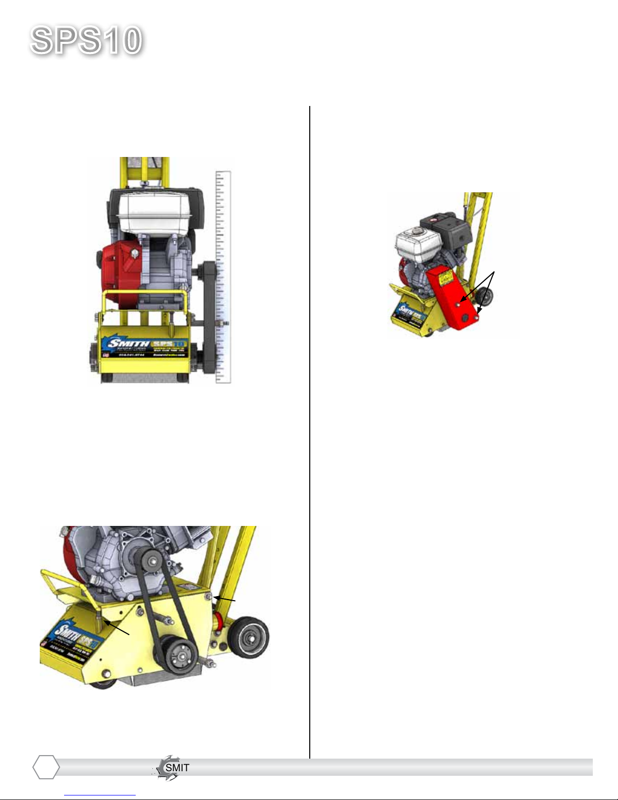
A) Both set screws (P/N 1010051) aligned on
hex shaft (P/N: 1065037) are torqued tight.
B) All three hex Bolts (P/N: 1010023) on
drum retaining plate (P/N: 1065054). Must be
aligned and tight.
• Check the Drive belt for wear, and adjust
(tighten), or replace as required.
• Check that the pulleys are aligned properly
to ensure the Drive belt is running true.
• Check wheel for wear and that they are
rotating properly, replace if worn. Clean
wheels of material build-up.
• The inside housing must be clean, and
remove any build-up from inside the cage so
cutters and drum rotate freely.
• Inspect and change drum bushings and
shafts every 40 hours, or when worn.
10

SMITH Manufacturing 1-954-941-9744 www.SmithMfg.com
SMITH Manufacturing 1-954-941-9744 www.SmithMfg.com
VERSION 11/2016
SPS10
Gas
DRUM REPLACEMENT
Normal wear may necessitate belt
tensioning or replacement.
Time of replacement will vary according to
usage and belt load factors.
Replacement is easy and requires a few
hand tools.
1. 9/16” socket or wrench
2. Rubber mallet
Before beginning servicing on any
gasoline-powered unit,
DISCONNECT SPARK PLUG WIRE!
1. Raise the cam lever to the up position so
the cutter drum is off the ground.
3. Remove the sideplate (this may require
the rubber mallet to break it loose)
4. Slide out drum assembly. (use precaution
as it is HEAVY)
1)
2)
3)
4)
5. Once the cutter drum is removed take to a
workbench for assembly.
a) Inspect condition of cutters,
spacers, shafts, bushings and drum.
6) Before replacing the drum onto hex shaft:
a) Check that all bearings are in
good working order
b) Remove dirt and material build-up
from inside drive carriage and drum.
c) Lube all metal contacts
7) Align and slide drum back onto the hex
shaft.
8) Replace side plate (lift-up and lock into
place) over hex shaft and secure hardware.
2. Remove the four hex head cap screws
from the sideplate using the 9/16” socket or
wrench.
*TIP: To reduce downtime, stock a
machine wear parts kit with spare
cutter drum assembly
11

SMITH Manufacturing 1-954-941-9744 www.SmithMfg.com
SPS10
VERSION 11/2016
Gas
SMITH Manufacturing 1-954-941-9744 www.SmithMfg.com
12
BELT REPLACEMENT
Normal wear may necessitate belt
tensioning or replacement.
Time of replacement will vary according to
usage and belt load factors.
Replacement is easy and requires a few
hand tools.
1. Two 9/16” wrenches
2. 3/4” wrench
3. 3/8” open-end wrench
4. Carpenters square or a straightedge
5. WD-40
6. Spark plug wrench
Before beginning servicing on any
gasoline-powered unit,
DISCONNECT SPARK PLUG WIRE!
1. Make sure the removable side cover is
installed. This ensures the drive ends are in
the proper position for servicing.
2. Remove the spark plug.
3. Clean the machine exterior so you can
locate all the appropriate parts.
4. Using a 3/4” wrench, remove the two
acorn nuts attaching the belt cover to the
side of the machine. Remove the cover and
set it aside.
2)
4)
5. Lubricate the motor plate (belt
tensioning) jackscrew with WD-40 on the
front left of the machine.
6. Use a 9/16” wrench to loosen the jack-
screw jam nut.
7. Using the 3/8” open-end wrench, begin to
screw the motor plate jackscrew back into
the long hex nut below it. Screw it all the
way until resistance is felt.
5), 6), 7
8)

SMITH Manufacturing 1-954-941-9744 www.SmithMfg.com
SMITH Manufacturing 1-954-941-9744 www.SmithMfg.com
VERSION 11/2016
SPS10
Gas
BELT REPLACEMENT
(CONTINUED)
8. Loosen (do not remove) the four bolts (2
per side) that secure the motor mount plate
to the main machine frame.
9. Loosen the four bolts attaching the mo-
tor to the motor plate. After sufciently
loosening all four, slide the motor back all
the way to the rear. This will loosen the belt
sufciently to remove it.
10. Either cut or roll off the belt from the
pulleys. If you roll it off, move it over one
groove at a time on the upper and lower
pulleys to completely remove it.
8)
9)
11. Roll the new belt on one groove at a
time (two or single multi-groove belt) on
both the top and bottom pulleys.
12. Using the straight edge, lay it across the
lower pulley outer face and against the
upper pulley. They must be directly over
top of each other to insure long belt life. If
adjustment is required, align before
tensioning the belt.
13. After installation, use the 3/8” open-end
wrench to screw out the belt tensioning
jackscrew under the motor plate to tension
the belts to your desired tension. Do not
over-tension the belt.
14. After the correct tension is reached,
tighten the front motor plate securing screw
on the belt side with the 9/16” box end
wrench.
12)
13)
14)
15. Now from the front of the machine
observe the motor plate to machine
alignment. Tightening the belts with the
jackscrew tends to cause the right side of
the motor plate to lift higher than the left
side. By pushing down on the right front
side you can level the plate and then
tighten the front right screw to secure in a
level position.
13
SMITH Manufacturing 1-954-941-9744 www.SmithMfg.com
SPS10
VERSION 11/2016
Gas
SMITH Manufacturing 1-954-941-9744 www.SmithMfg.com
BELT REPLACEMENT
(CONTINUED)
18. Replace the belt cover using the 3/4“
box wrench.
19. Replace the spark plug and the spark
plug wire.
16. Now tighten the rear securing bolts with
the two 9/16” wrenches.
17. Tighten the motor plate jackscrew
retaining nut with a 9/16” wrench to prevent
it from turning.
17)
16)
18)
BELT ALIGNMENT
If the unit has premature belt wear, breakage
or pulley problems, the issue may be
incorrect alignment or excessive belt
tensioning. All pulleys must be aligned
directly above each other to ensure belt
integrity.
This includes possible timing belts used on
newer models. Incorrect alignment wears
the sides of the belts excessively and will
cause slippage.
1. Use a long straight edge (carpenters
square) to check alignment during belt
tensioning or belt replacement time.
2. By laying the straight edge against the
outer face of the lower pulley, the square will
extend up and rest against the outer face of
the upper (engine pulley). If not, move the
motor pulley in or out to obtain alignment.
3. If replacing pulleys (top or bottom) be sure
to place the pulley on the same plane as the
original one to ensure alignment.
14
SMITH Manufacturing 1-954-941-9744 www.SmithMfg.com
SMITH Manufacturing 1-954-941-9744 www.SmithMfg.com
VERSION 11/2016
SPS10
Gas
BEARING REPLACEMENT
Before reading ahead go back and follow
the instructions on how to remove the belt
from the machine. Bearing replacement is
easy and requires a few additional hand
tools.
1. 7/16” socket or wrench
2. 1/2” socket or wrench
3. 1” open-end wrench
4. 3/16” Hex Key
5. 5/32” Hex Key
6. 1/8” Hex Key
Before beginning servicing on any
gasoline-powered unit,
DISCONNECT SPARK PLUG WIRE!
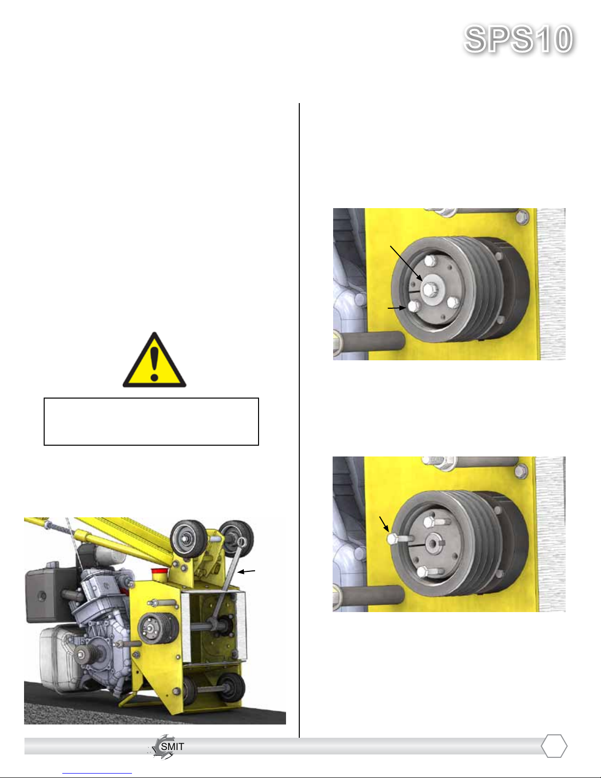
1. Once the belt is removed from the ma-
chine, tip the machine over towards the
FRONT and place the 1” wrench over the
hex shaft to prevent it from rotating.
2. Remove the center screw using the 1/2”
socket
3A. Remove the remaining 3 screws using
the 7/16” socket and insert them by hand
into the threaded holes as shown below (3B)
1)
2)
3A)
3B. Once all 3 screws are in, begin to turn
them using a socket and do so EVENLY to
allow the bushing to back out smoothly.
Once the bushing is out, remove the pulley
and key.
3B)
15
SMITH Manufacturing 1-954-941-9744 www.SmithMfg.com
SPS10
VERSION 11/2016
Gas
SMITH Manufacturing 1-954-941-9744 www.SmithMfg.com
BEARING REPLACEMENT
(CONTINUED)
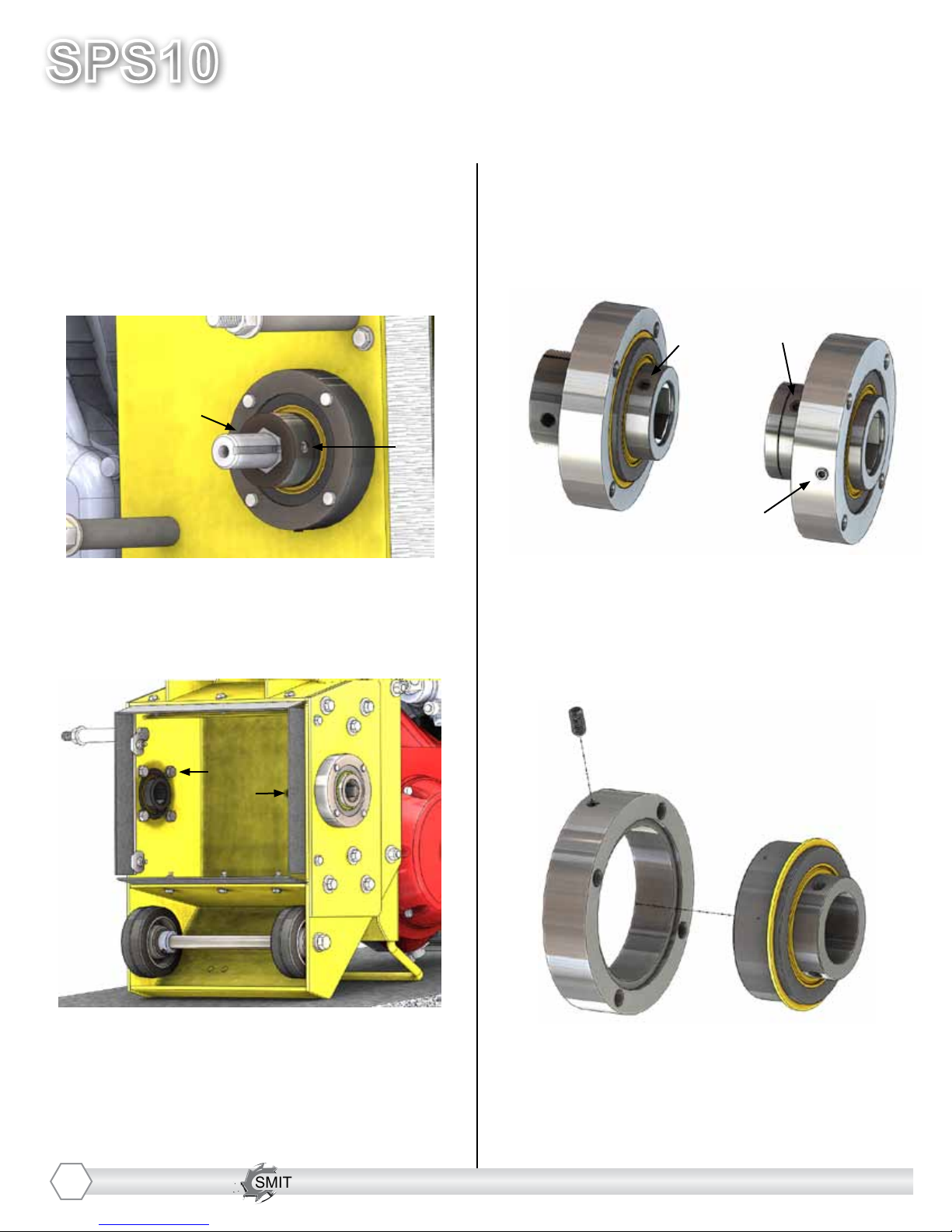
4. Slide the shaft out by removing the 2 set
screws locking it in place using the 3/16”
hex key
5. Remove the bearing assemblies on both
sides on the machine using the 9/16” socket
6. At this point remove the hex bushings
from the bearing assemblies (note that the
belt side bushing is much thicker and has
holes for set screws) using the 5/32” hex
key
6)
4)
4)
5)
5)
6)
BELT SIDE
7. With the hex bushings out, the remaining
bearings and housings are the same. To
remove the bearing from the housing use
the 1/8” hex key to remove the set screw on
the housing and then tap out the bearing us-
ing a mallet
7)
8. Reverse the process and apply thread
locking uid (loctite) to the set screws
16
SMITH Manufacturing 1-954-941-9744 www.SmithMfg.com
SMITH Manufacturing 1-954-941-9744 www.SmithMfg.com
VERSION 11/2016
SPS10
Gas
OPTIONAL EQUIPMENT
• HIGH SPEED KIT
The high speed kit is used with the Diamond
Shave-it Drum Assembly ONLY
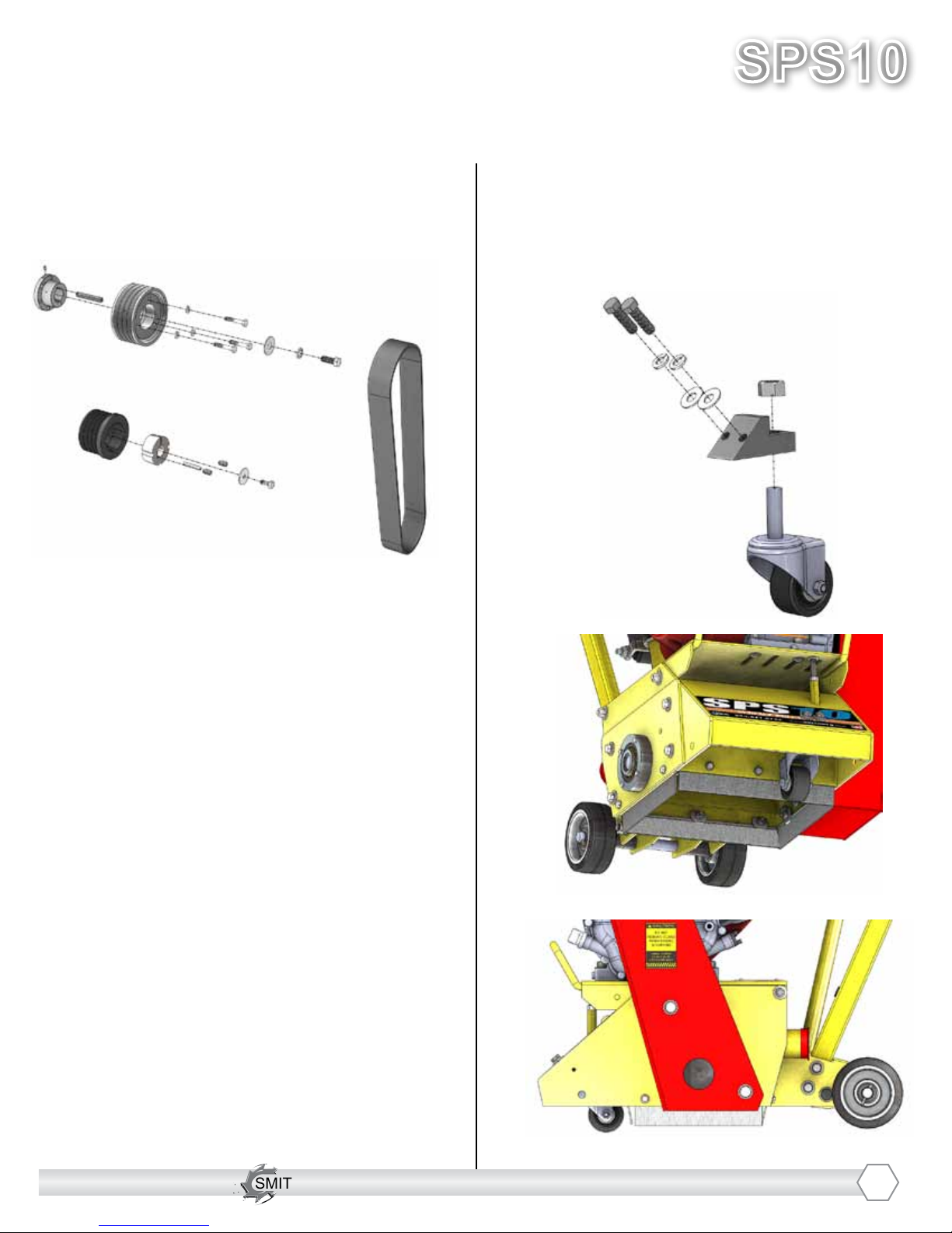
• SWIVEL WHEEL
The swivel wheel allows you to move the
machine not only forward and backward in
a straight line, but also from side to side to
eliminate grooves!
17
1. Remove belt guard, belt (1081008), and
both pulleys from the ail setup machine.
2. Set the pulley (1010554) from the motor
aside, and move the pulley (1065020) from
the drive shaft to the engine’s shaft (the
bushing required (1010559) is part of the
high speed kit).
3. Place the pulley (X3.00.219.1) and other
bushing (X3.00.220.3) on the drive shaft.
4. Before tightening the pulleys in place with
the bushings, put the new belt (1081008.W)
into place over the pulleys.
5.Align the pulleys using a straight edge, and
tighten them into place with the bushings.
Use locktite 243 on all pulley set screws.
6. Replace belt guard.
HIGH SPEED KIT INSTALLATION

SMITH Manufacturing 1-954-941-9744 www.SmithMfg.com
SPS10
VERSION 11/2016
Gas
SMITH Manufacturing 1-954-941-9744 www.SmithMfg.com
OPTIONAL EQUIPMENT
• SPS CRADLE
(Cam Release Adjustment Dampener Life
Extender) shock assembly prevents hard
drum drops
• CENTER STAND BRAKE KIT
The Center Stand Brake Kit allows for safe
“parking” of the SPS10 on inclined surfaces
18
• TACH/HOUR METER
Maintenance meter for service and use
control
SMITH Manufacturing 1-954-941-9744 www.SmithMfg.com
SMITH Manufacturing 1-954-941-9744 www.SmithMfg.com
VERSION 11/2016
SPS10
Gas
OPTIONAL EQUIPMENT
• POINTER/DIRECTIONAL
SIGHT GUIDE SYSTEM
Allows operator to make straight passes
easier
• WATER CONTROLS
Used to extend life on Diamond drum
applications and for dust control on all others.
Available with or without 5 gallon tank.
19
SMITH Manufacturing 1-954-941-9744 www.SmithMfg.com
SPS10
VERSION 11/2016
Gas
SMITH Manufacturing 1-954-941-9744 www.SmithMfg.com
OPTIONAL EQUIPMENT
• BALL MOUNT HITCH
Allows attachment to other components
• EDGER DRUM ASSEMBLY
Available for Diamond blades and cutter
applications
20
Other manuals for SPS10
1
Table of contents
Other Smith Construction Equipment manuals


