Ergo Source XFT User manual
Assembly Instructions
P.O. Box 695
Wayzata, MN 55391
Customer Service 952-404-1969
www.ergosource.com
email - info@ergosource.com
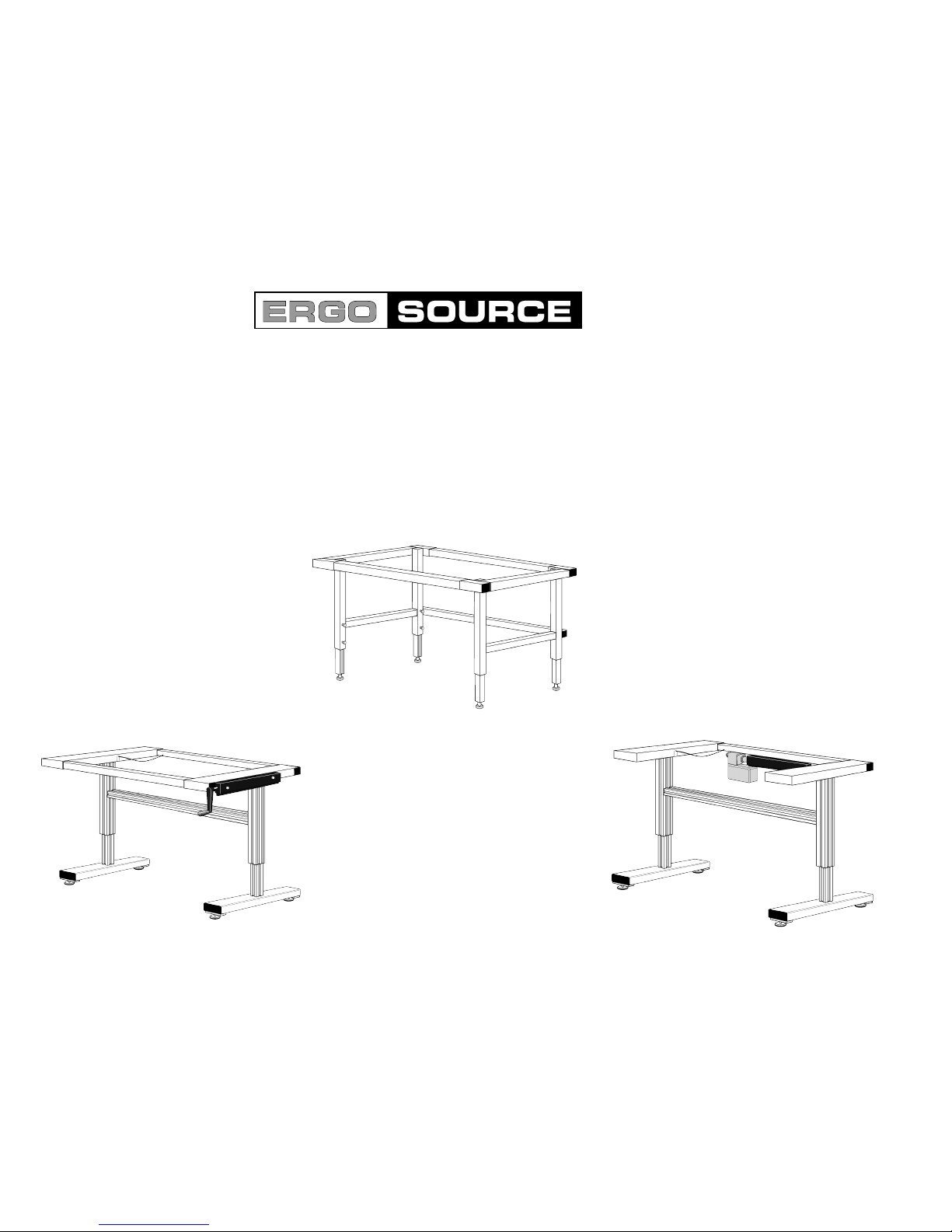
Levitech
Table Systems
and
Accessories
Userʼs Guide Parts List


Ta bl e o f C o n t e n t s
How to Put the Levitech Table Together 1
How to add a Hanging Pencil or Pencil/File Drawer 2
How to Add a Table Top 3
How to Add a Full Tilt Top 4
How to Add a Cut-Out Tilt Top 5
How to Raise the Cut-Out Tilt Top 9
Cutting the Rails to Custom Lengths 10
Setting Up the Hydreaulic Tilt Table 10
How to Operate the Electric Table 11
Workstation Accessories Assembly 12
Workstation Accessories 14-15
XHT Exploded View and Parts List 16-17
XHCT Exploded View and Parts List 18-19
LH4T Exploded View and Parts List 20-21

How to Put the Levitech Table Together
CAUTION
Be sure to read all instructions before assembling the Levitech Table.
WARNING
Do not disconnect or cut the hydraulic lines at any point.
They are factory sealed and have no user serviceable parts.
Note:
Motorized tables are not assembled when shipped. If you have purchased a
motorized table, follow the assembly from step 1. To mount the motor on the
rear rail, follow steps 1-6 and then skip to the section entitled “Changing the
Location of the Electric Motor” on page 11.
1a). For the X-Series Tables, spread the legs to the width of the strut
supplied. See page 16 or 17 for instructions. Insert 10-32X1.25 Socket Head
Cap Screw (#31 Part No. 19F128KCS) through holes in cylinder washer(#24
Part No.1015 and start screws in nut plate(#25 Part No.1017), repeat assem-
bly for both ends of strut. Then slide strut assembly into vertical channel of
outer leg. Tighten strut six inches from under side of table arm support or
locate as desired.
1b). For the L-Series Tables, spread the legs to the width of the rails
supplied. If the length of the rail will make the table too wide for your
application, refer to the section entitled “Cutting Rails to Custom Lengths” on
page 10.
2. Insert (2) nut plates inside each rail and install rail inside upper sleeves
(see diagram #20). NOTE! Slide one additional nut plate in upper rear rail for
motorized tables (see page 11).
3. Adjust the bottom rail(s) so you can cap one of the sleeves with an endcap
(the rail should be recessed at least 3/8” -see Figure 1). Put the nut plate in
the nut plate channel at the bottom of the rail, and screw the 3/8” socket
through the holes in the sleeve and tighten. Install endcaps with a rubber mal-
let. Tap the endcap in gently so it goes in evenly and not at an angle. Slide
the rail gently against the endcap. Be sure to slide the rail gently or the end-
cap will de dislodged.
3. Continued Figure 1.
Bottom Rails Shown
Figure 1. The nut plate should be in the nut plate channel at the bottom of the
rail. Be sure the rail is recessed at least 3/8” so the endcap will fit in the end
of the sleeve.
4. Slide the nut plate in the nut plate channel at the bottom of the rail until it is
over the holes in the capped sleeve.
5. Screw the 3/8” socket head cap screws through the holes in the sleeve and
the nut plate. Finger tighten the cap screws; leave the cap screws finger tight
unitl step #6.
6. Repeat steps 2-5 for both legs until all the rails are in place and the cap
screws are ginger tight. Be sure to leave at least 3/8” clearance at the end of
each sleeve for the endcaps to fit in Figure 1. Cap every open sleeve with a
plastic endcap.
7. Now tighten all cap screws firmly with the 5/16” hex key (supplied).
NOTE:
Verify that the legs are plumb to prevent inner legs from jamming.
1
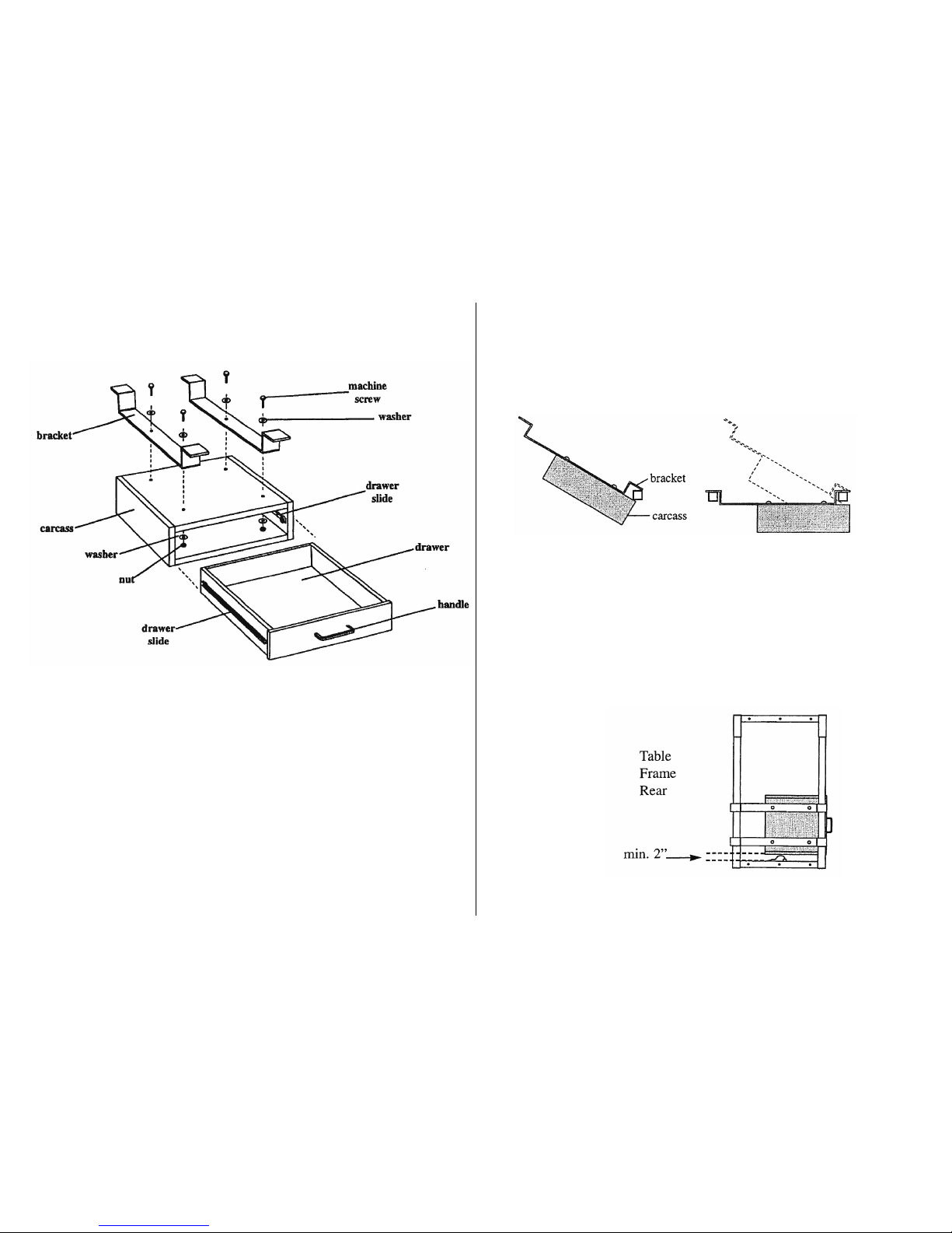
How to Add a Hanging Pencil or
Pencil/File Drawer
NOTE:
Be sure to add all drawers before attaching to the table top.
1. Take the drawer out of the carcass.
2. Remove the screws holding the handle in place on the inside of the draw-
er. Put the handle on the outside and secure it by seating the screws and
washers on the inside.
3. Lower the drawer between the rails with the
carcass toward the front rail. Tilt the front brackets toward the front rail.
Slowly slide the carcass toward the front rail so the rail goes into the jaw
formed by the bottom of the bracket and the top of the carcass (Figure
3). Be sure the brackets are not on top of the sleeves.
Figure 3. The front rail goes between the bracket and the carcass.
4. Lower the rear bracket onto the rear rail.
5. For hydraulic tables, be sure there is at least 2” between the table
arm support and the carcass (Figure 4). If the carcass is closer than 2”,
the hydraulic hoses may be kinked or otherwise bepermanently
damaged.
Figure 4.
Top view of
drawer
assembly.
6. Retrun the drawer to the carcass.
2
NOTE:
If you are adding a recessed top to the XHT table be sure the front rail has not been installed.
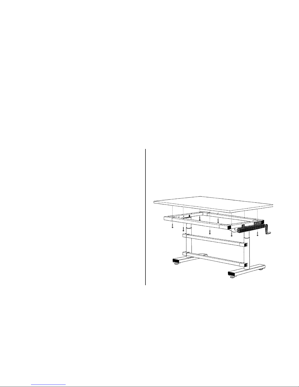
Note: Drawer unit(s) must be installed before adding table top.
1. Be sure to add at least two new holes in each rail. Place the holes equal
distant from the sides of the table. Use a 5/16” bit to drill the new holes. Each
rail has a chamfer to mark a center line and to keep the drill bit from skittering
while you are drilling.
2. When all new holes have been drilled, put the top on the table. If your table
is a XHT, be sure the table top does not extend more than 2” beyond the front
sleeve. If your table is a XHCT, be sure the table top does not extend more than
3 7/8” beyond the front edge of the table support arm.
3. With a pencil, mark all the holes in the rail and table arm
supports on the underside of the table top.
4. Use the 1/8” bit to drill pilot holes in the underside of the table top. Do not
drill holes deeper than 3/4”.
5. Using the self-tappling screws, fasten the table top to the frame.
How to Add a Table Top
3
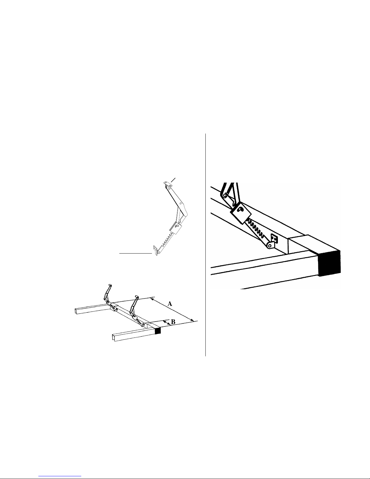
2. Measure the proper distance along the interior vertical face of the rear rail and mark it.
Center the lower mounting plate of the mechancial tilt brackets on the mark (Figure 7). Use
the holes in the brackets to mark the holes to drill.
Figure 7. Refer to the chart in step 1. If your table top is width A, center the mechancial tilt
brackts on a mark at the distance B fromthe edge.
How to Add a Full Tilt Top (XHT & XHCT)
NOTE:
On the XHT Model, drawers must be installed before installing the table top.
1. Use this chart to find the proper distance to measure along the interior vertical face of the
rear rail to attach your mechanical tilt brackets (Figure 6):
Fasten to the under-
A B side of the top
If your table top Place the mechanical tilt
is this wide: brackets this far from the
sides:
36-48” 8”
49-60” 12”
61” + 16”
Figure 6. Mechanical tilt bracket.
Fasten to inside of
rear rail
3. Drill the holes and attach the lower mounting plate with the
1/4-20 x 1” machine screws, lock washers and nuts provided
(Figure 8). Be sure the distance from the top of the rail to the top
of the lower mounting plate is the same for all mechanical tilt
brackets.
Figure 8. Be sure the distance from the top of the rail to the top
of the lower mounting plate is the same for all brackets.
4. If you have an XHCT table, follow step #5 then skip to step #7.
If you have an XHT table, follow step #6 and continue with step
#7.
4
Adding the Full Tilt To an XHCT
5. A) Place the top on the table and adjust it as desired. Be sure the table top
does not extend more than 3 1/8” beyond the front edge of the XHCT table arm
support.
B) With a pencil, mark the table arm support position on the underside of
the table top. Be sure to mark the inside and the front of the table arm support
(Figure 9).
C) Remove the table top and turn it over. Align one of the leaf hinges on the
table arm support guidelines just drawn. Be sure the pin of the hinge is toward
the front edge of the table top. Mark the holes of the hinge on the table top.
Figure 9. Mark the side and front of the table arm support on the underside of
the table top, then mark the holes in the hinges. Be sure the pin of the hinge is
toward the front edge of the table top.
D) Remove the hinge and drill the holes. Do not drill holes deeper than 3/4”.
E) Repeat steps C & D for the other hinge.
continued,
F) NOTE: Before you attach hinges to the table top, mark and drill the
hinge holes on the table arm supports. Align one of the leaf hinges on the
table arm support. Be sure the pin of the hinge is toward the fron of the
table. Mark the holes of the hinge on the table arm support.
G) Remove the hinge and drill the holes.
Figure 10. Screw both hinges in place on the table top before attaching
then to the table arm supports.
H) Repeat steps F & G for the other hinge.
I) Screw both hinges in place on the table top before
attaching them to the table arm supports (Figure 10).
J) Hold the table top so the holes in the other leaf of the hinge match the
holes in the table arm support.
K) Screw the machine screws into the table arm supports. Add the nuts
from the bottom. Support the table top until all fasteners are in place and
tight.
L) Lower table top slowly onto the table arm supports.
5

Adding the Full Tilt Top to an XHT
6. A) Place the top on the table and adjust it as desired. Be sure the table
top does not extend more than 1 1/4” beyond the front edge of the table
arm support.
B) With a pencil, mark a line on the underside of the table top along the
interior vertical face of the front rail (Figure 11). Remove the table top and
turn it over.
C) Align one of the leaf hinges along the line you have just drawn. Be
sure the ginge is at least 6” in from the edge of the table. Mark the holes of
the hinge on the table top.
D) Remove the hinge and drill holes. Do not drill holes deeper than
3/4”.
E) Repeat steps C & D for the other hinge.
Figure 11. Be sure the pin of the hinge is toward the front edge of the table
top and that the hinges are the same
distance in from the edge, at least 6”.
Continued,
F) Screw the hinges in place on the table top.
G) Replace the top on the table and adjust it as desired. Be sure the
free leaf of the hinge is hanging down in front of the front rail (Figure 12).
H) Drill holes in the front rail through the holes in the leaf hinges.
I) Screw in the machine screws and add the nuts and lock washers
through the nut plate channel.
Figure 12
Be sure the free leaf of the hinge is hanging in front of the front rail.
6
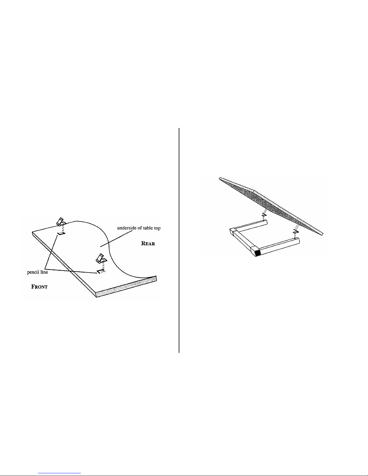
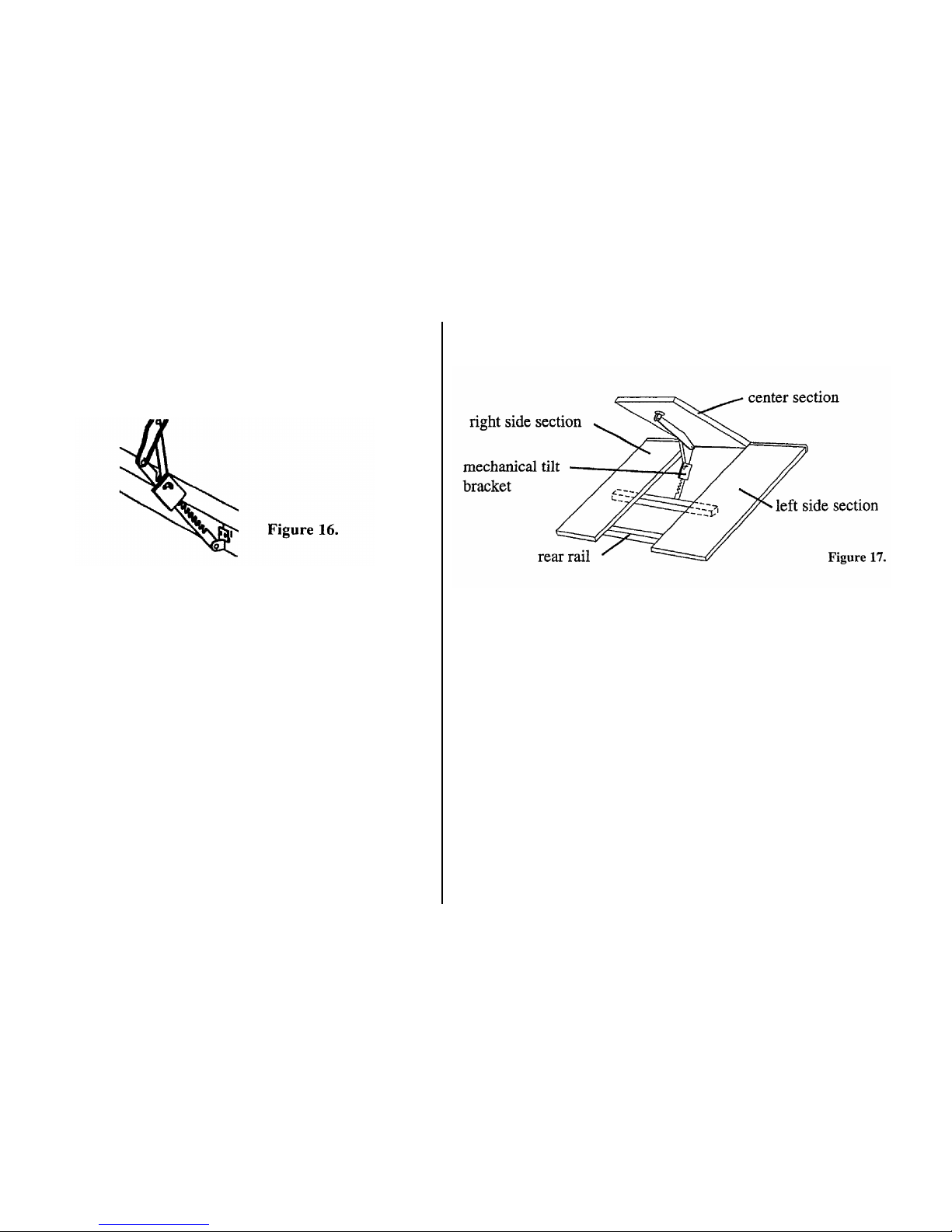
7. For XHT and XHCT
Collapse one of the mechanical tilt brackets by expanding it to its maximum
angle and then gently bringing the two halves together. Hold the free end of the
bracket against the underside of the table top and mark the holes to drill.
Repeat this step for any other brackets.
8. Lift the table top and drill the pilot holes. Do not drill holes deeper than 3/4”
9. Let the table top down and screw the free ends of the
mechanical tilt brackets to the table top (Figure 13). Installation
is complete. To raise and lower the top, see the section entitled “How to Raise
the Cut-Out Tilt Top” on Page 9.
Figure 13
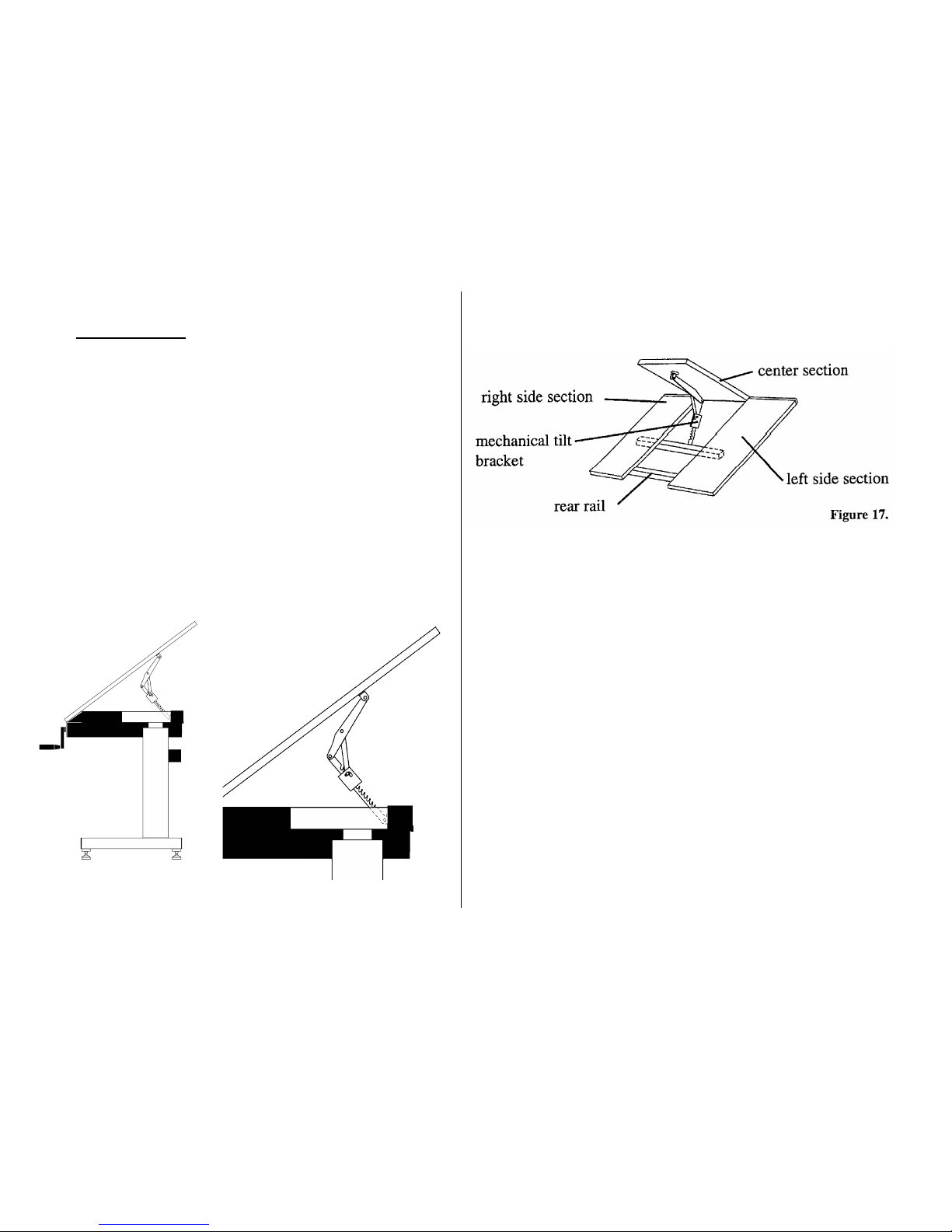
HOW to Add A Cut-Out Tilt Top
(XHT Only)
1. Place and center all three top sections on the table frame. Leave approxi-
mately 1/8” of a gap between each section. Make sure that the table top
edge does not extend more than 2” beyond the front sleeve. All sections
should be parallel and all three front edges should be flush.
NOTE: For the purpose of these instructions we will show the center section
tilting, however any one of the sections may be raised to fit your application.
2. With a pencil, mark all the holes in the table arm supports on the under-
side of the right and left side top sections.
NOTE: Leave the center section in place while you are marking, drilling and
fastening side sections in order to ensure proper alignment.
3. Turn one of the side sections over and use the 1/8” bit to drill pilot holes in
the underside of the table top section. Do not drill holes deeper than 3/4”.
4. Turn the side section right side up and screw the self-tapping screws
through the holes in the table arm supports and the rails and then into the
table top.
7

Continued,
5. Repeat Steps 3 and 4 for the other side section.
6. Remove the center section. Fasten the 42” rail (provided) to the under-
side of the right and left table sections with the machine screws provided
(Figure 14). You will need to mark and drill holes in the 42” rail that match
the predirilled holes on the underside of each section. NOTE: Make sure to
drill the 2sets of holes at an equal distance from the outside edges of the
42” rail.
Figure 14. The 42” rail and the peel-and-stick pads must be in place before
adding the hinged section.
7. Place peel-and-stick rubber pads on the rear rail as shown in Figure 14.
8. Place the hinge on the front rail as shown in Figure 15 and center it
between the two side panels.
Figure 15
Continued,
9. Replace the center section and center it as desired. Make sure all three
table edges are flush with the hinge in place and that there is an even gap
on the left and right side of the center section.
10. Mark the position of the hinge on the underside of the centert section of
the table top. Mark along the side of the knuckle facing the front of the
table.
11. Remove the center section and turn it over. Align the knuckle of the
hinge along the guideline just drawn, keeping it centered on the table top
section. Be sure the knuckle is toward the front edge of the table top sec-
tion.
12. Using the hinge as a template, mark the holes of the hinge on the
underside of the table top.
13. Remove the hinge and drill the holes. Do not drill holes deeper than
3/4”.
14. Screw the hinge in place on the table top.
15. Replace the center section with the free leaf of the hinge hanging down
in front of the front rail. Re-center the center section between the side sec-
tion.
16. Drive the self tapping screws into the front face of the rail.
17. Measure the center of the inside vertical face of the 42” rail. Mark with
a vertical straight line.
8
Continued,
18. Place the lower mounting plate of the mechanical tilt bracket so that the
two drill holes are centered on either side of the vertical line (Figure 16).
Mark the holes to drill
19. Drill the holes and attach the lower mounting plate to the rail face with
the 2” machine screws, sleeves, lock washers and nuts provided.
20. Collapse the mechanical tilt bracket by expanding it to its maximum
angle and then slowly bringing the two halves together. With the center sec-
tion all the way down (horizontal) hold the free end of the bracket against
the underside of the center section and mark the pilot holes.
21. Lift the center section and drill the pilot holes. Do not drill holes deeper
than 3/4”.
22. Let the center section down and screw the free ends of the mechanical
tilt brackets to the table top with the screws
provided (Figure 16).
How to Raise the Cut-Out Tilt Top
1. Grasp the cut-out top at the upper edge, lift gently to the desired angle, and
release. The tilt bracket should lock in place and keep the cut-out top at the
desired angle.
2. To return the cut-out top to its level position, grasp the cut-out top on the
upper edge and lift gently to the maximum angle (Figure 17). The tilt bracket will
release. Slowly lower the cut-out top to its level position.
3. To increase the angle of the cut-out top, grasp it on the top edge, lift gently to
the desired angle, and release it.
4. To decrease the angle of the cut-out top, grasp it on the upper edge and lift
gently to the maximum angle. The tilt bracket will reslease. Slowly lover the top
past the desired angle, then raise the top to the desired angle and release it.
The tilt bracket will lock in place. The tilt bracket indexes at 14 stops.
9
Cutting the Rails to Custom Lengths
1. Determine your overall table width.
2. Cut the rails at least 3/4” shorter than the overall desired table width.
3. The rails can be cut with a carbide-tipped blade in a power miter box or a
hacksaw.
4. Imperfect cuts will be hidden inside the sleeves when assembly is com-
plete.
5. To complete table assembly, return to Step 1 in the section entitled “How
to Put the Levitech Table Together”.
Setting up the Hydraulic Tilt Table
1. The hydraulic tilt top table is shipped fully assembled.
2. Before tilting the table top, be sure the roller will track front to rear. The
rollers are in the proper position when they are parallel to the sides and the
roller axle is parallel to the front and rear of the table (Figure 18).
Figure 18
10
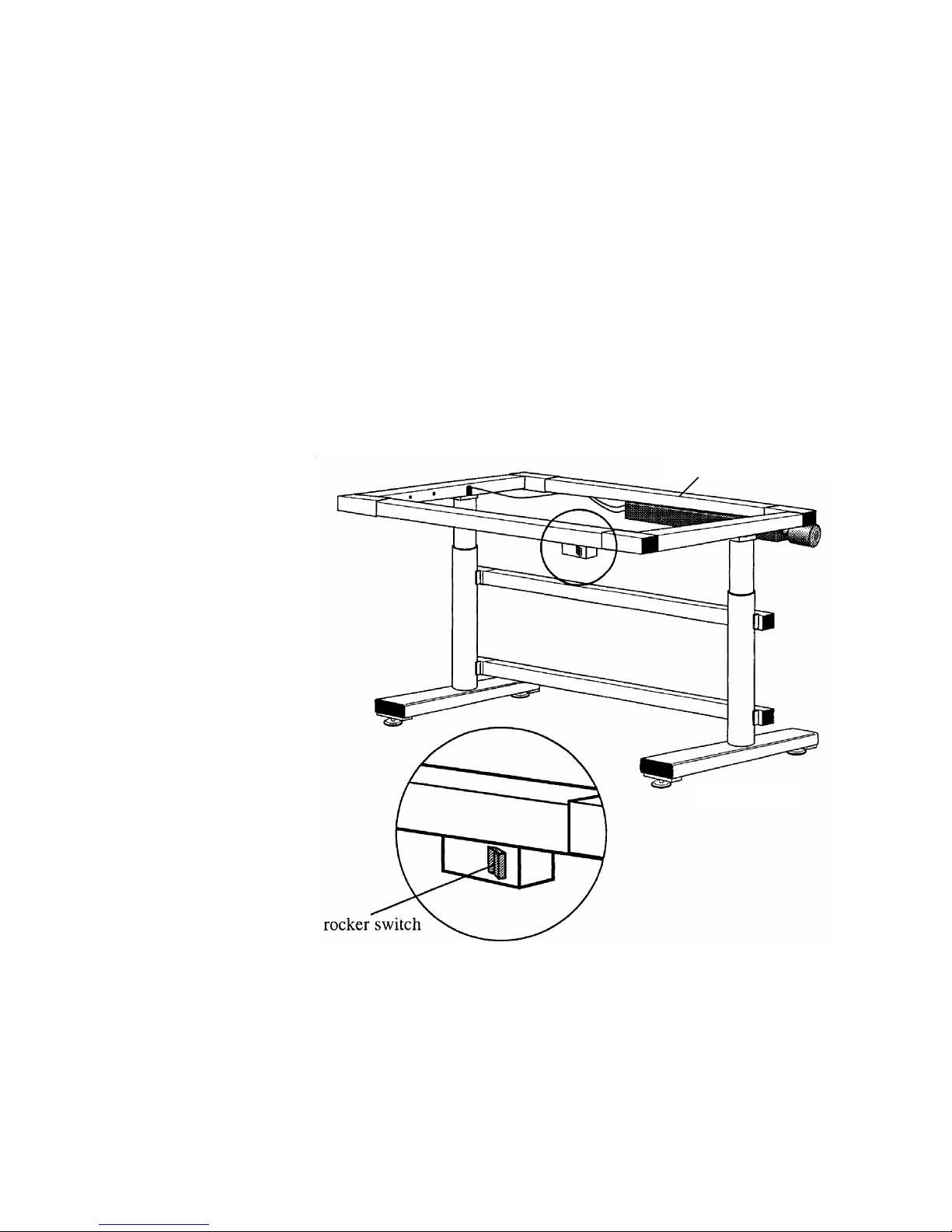
1. Plug the motor into any 110 Volt outlet.
2. The rocker switch controls the height of the table (Figure 20). It is in the off position when released.
To raise the table, press the bottom half of the switch. To stop the table at the desired height, release
the switch.
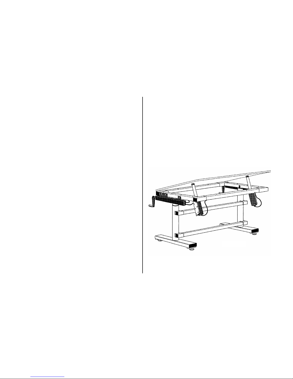
How to Operate the Electric Table
Place one (1) additional nutplate in top
rear rail for mount motor
Figure 20
11

Motorized Table Assembly
1. Verify that motor is unplugged.
2. Slide nut plate for motor mount in upper rear rail.
3. Position and secure lift using 2 each 3/8-16 x 3/4” socket head cap screws. Assembly from the table arm support by removing the
three screws in the mounting plate.
Workstation Accessories Assembly
Planning Your Levitech Workstation:
1. List and prioritize all articles that are utilized in the execu-
tion of the task(s). Included components, tools, instruments,
references and equipment.
2. Based on the prioritization of the articles above. Plan a
workstation layout assigning each location that will minimize
the operators reach and optimize the operators vision.
3. Evaluate the flow of raw and finished material to and from
the workstation. Verify that the safest and most efficient
methods are being utilized.
Assembly Tools Required:
1. Open End Wrench or Socket 1/2” (13mm).
2. Open End Wrench or Socket 9/16” (14mm).
3. 2 ft. Level.
4. Drill and Drill Bits.
5. Screw driver, hex keys as needed for hardware provided by
others.
12
Workstation Accessories Assembly
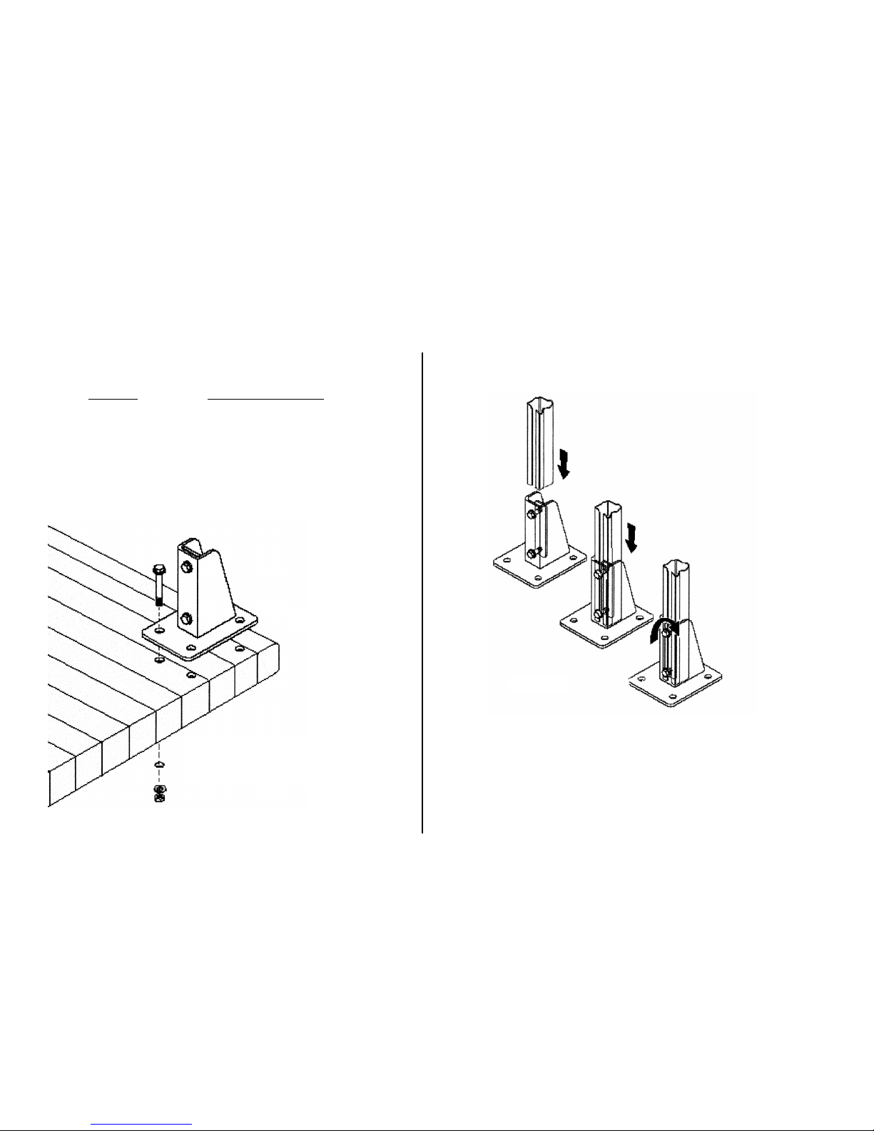
1. Determine bench mount shoe (WS50-TB) location. Inside dimension
of columns for different table top sizes is as follows:
To p W i d t h Inside to Inside Column
36” 30”
48” 42”
60” 54”
72” 66”
Drill holes and assemble bench
mount shoe . Nuts, bolts and
washers by others.
Figure 21.
2. Slide vertical support columns into bench mount shoe and fasten using the
9/16” wrench (Figure 22).
3. Slide all other components into the columns. Insert first components that
you need closest to the work surface top. Properly position components
making sure unit is plumb, level and square. Adjust components to fit the
individual operator. Tighten all cap screws, securely clamping all components
to the columns and rails. Install end plugs as needed. Mount lights, bins, etc.
Verify that the final layout and adjustments will maximize the operator
efficiencies and comforts.
13
Figure 22

Workstation Accessories
LWS5-BB(XX)
WS50-TN
LWS5-TO(X)
LW5SA-0014
LW5EB-0015
LW5FM-0011
LW5CT-0017
LW5KT-0018
LW5MT-0028
LW5BR-1018
LW5BR-1028
w/Bins
W5CB-1920
14
Accessories Parts List
LWS-TTM Bench Mount Shoe
WS50-BB(XX)* Bin Rail
LWS5-TO(X)* Support Column
LWS3-T05 Support Column
W5CA-0018 Swing Arm
LW5BR-1018 Bin Rack-Single
LW5BR-2018 Bin Rack-Double
LWS5-BB(XX) Bin Bar
LW5CT-0017 CRT Swivel Tray
LW5KT-0018 Keyboard Tray
w/Supports
LW5MT-0028 Mouse Pad Tray
LW5FM-0011 Front Mont Base
Assembly
W5CA-0018 Swing Arm
LW5EB-0015 5” Elbow Assembly
LW5SA-0014 10” Swing Arm
Assembly
LWS-3EP End Plug
LWS-5EP End Plug
LWS-AB Angle Bracket Assembly
LWS5-SS(XX)* Shelf w/Brackets
LWS3-HG Hanger Assembly
LWS5-HG Hanger Assembly
WBL-204A Task Light
WS50-TN Track Nut
LWPB-30(XX) Power Bar
* (X) means there is more than one number for
different sizes of the part.
15

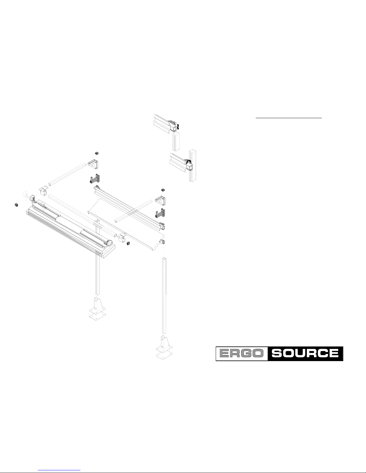
Models XFT, XHT, XET
Illustrated Parts List
16

17
This manual suits for next models
8
Table of contents
Popular Indoor Furnishing manuals by other brands


physa
physa PHY - CM - 10 instruction manual

Bretford
Bretford FLIP TOP QUATTRO TABLE Assembly instructions

Venjakob
Venjakob 4108 Assembly instructions

Tennsco
Tennsco 1871 Assembly Instructions/Parts Manual

Ergonomic Seating Solutions
Ergonomic Seating Solutions OPERA 50 instructions

Classy Home
Classy Home BW19-02T Assembly instructions


