Ergo ERGO 8 User manual
Water Softener | User Manual
Adoucisseur d’eau | Guide d’utilisation
www.puricom.eu
ENG FR

1. CARACTERÍSTICAS PRINCIPALES
FÁCIL LLENADO DE SAL
Cómodo llenado de sal especial para descalcificadores.
HIDRÁULICO
Sin alimentación eléctrica, ausencia de programación y de problemas.
Mayor caudal de agua dispensada
Grifo de diseño exclusivo.
Minimiza la migración metálica
REGENERACIÓN ULTRA RÁPIDA
Lavados completos en 15 minutos.
BAJO CONSUMO
Regeneraciones más eficientes.
VÁLVULA MEZCLADORA
Permite regular el grado de dureza residual.
BY-PASS INTEGRADO
Permite aislar el equipo de la instalación.
VÁLVULA ESSENTIAL
Lista para funcionar solo con un giro de destornillador.
CONSERVE ESTE MANUAL QUE INCLUYE LOS APARTADOS DE LIBRO DE SERVICIO Y GARANTÍAS, PARA PODER
PROPORCIONARLE UN MEJOR SERVICIO POST VENTA.
PLEASE KEEP THIS MANUAL, WHICH INCLUDES THE SERVICE BOOK, IN ORDER TO
PROVIDE YOU WITH A BETTER AFTER-SALES SERVICE.
1. CARACTERÍSTICAS PRINCIPALES
FÁCIL LLENADO DE SAL
Cómodo llenado de sal especial para descalcificadores.
HIDRÁULICO
Sin alimentación eléctrica, ausencia de programación y de problemas.
Mayor caudal de agua dispensada
Grifo de diseño exclusivo.
Minimiza la migración metálica
REGENERACIÓN ULTRA RÁPIDA
Lavados completos en 15 minutos.
BAJO CONSUMO
Regeneraciones más eficientes.
VÁLVULA MEZCLADORA
Permite regular el grado de dureza residual.
BY-PASS INTEGRADO
Permite aislar el equipo de la instalación.
VÁLVULA ESSENTIAL
Lista para funcionar solo con un giro de destornillador.
CONSERVE ESTE MANUAL QUE INCLUYE LOS APARTADOS DE LIBRO DE SERVICIO Y GARANTÍAS, PARA PODER
PROPORCIONARLE UN MEJOR SERVICIO POST VENTA.
AFIN DE VOUS APPORTER UN MEILLEUR SERVICE APRÈS-VENTE, VEUILLEZ CONSERVER
CE MANUEL, INCLUANT LE LIVRET D’ENTRETIEN.
1. CARACTERÍSTICAS PRINCIPALES
FÁCIL LLENADO DE SAL
Cómodo llenado de sal especial para descalcificadores.
HIDRÁULICO
Sin alimentación eléctrica, ausencia de programación y de problemas.
Mayor caudal de agua dispensada
Grifo de diseño exclusivo.
Minimiza la migración metálica
REGENERACIÓN ULTRA RÁPIDA
Lavados completos en 15 minutos.
BAJO CONSUMO
Regeneraciones más eficientes.
VÁLVULA MEZCLADORA
Permite regular el grado de dureza residual.
BY-PASS INTEGRADO
Permite aislar el equipo de la instalación.
VÁLVULA ESSENTIAL
Lista para funcionar solo con un giro de destornillador.
CONSERVE ESTE MANUAL QUE INCLUYE LOS APARTADOS DE LIBRO DE SERVICIO Y GARANTÍAS, PARA PODER
PROPORCIONARLE UN MEJOR SERVICIO POST VENTA.
HIGH-SPEED REGENERATION - full wash in 15 minutes
RÉGÉNÉRATION HAUTE-VITESSE - régénération complète en 15 minutes
LOW CONSUMPTION - more ecient regeneration
BASSE CONSOMMATION - régénération plus ecace
MIXING VALVE - the residual hardness degree can be regulated
VANNE DE MÉLANGE - L’équipement peut être isolé de l’installation
BUILT-IN BY-PASS - the equipment can be isolated from the installation
BY-PASS INTÉGRÉ - L’équipement peut être isolé de l’installation
ERGO VALVE - ready to work with a single turn from a screwdriver
VANNE ERGO - Prêt à être utilisé d’un simple tour de tournevis
EASY SALT REFILLING - specifically designed easy to load salt
RECHARGEMENT EN SEL SIMPLIFIÉ - Rechargement en sel facilité grâce à
sa conception spécifique pour les adoucisseurs d’eau
HYDRAULIC - no electrical power supply, so no settings to set
FONCTIONNEMENT HYDRAULIQUE - sans électricité, sans paramétrage et
sans contrainte.
The Ergo Water Conditioning Systems are Tested and Certified by
WQA under NSF/ANSI 61 for Materials Safety Requirements Only. Not
Certified for Contaminant Reductions or Structural Integrity by WQA.
L’adoucisseurs d’eau Ergo est testé et certifié par WQA sous la norme
NSF/ANSI 61 seulement pour les exigences en matière de sécurité du
matériel. La réduction des contaminants ou l’intégrité structurelle ne
sont pas certifiées par la WQA.
CONTENTS
1. Presentation_______________________________________________ 4
2. Introduction ______________________________________________ 4
3. Technical Specifications ______________________________________8
4. Unpacking and Verification of the Content______________________ 9
5. Prior Warnings ____________________________________________ 9
6. Equipment Installation ______________________________________ 11
7. Ergo Programmer __________________________________________ 13
8. Hydraulic Start-Up _________________________________________ 14
9. By-pass and Mixing ________________________________________ 15
10. Maintenance and Sanitizing _________________________________ 15
11. Frequently Asked Questions _________________________________ 17
12. Service Book: User ________________________________________ 18
ENG
FR SOMMAIRE
1. Présentation______________________________________________ 20
2. Introduction ______________________________________________ 21
3. Caractéristiques Techniques ________________________________ 24
4. Déballage et Vérification du Contenu __________________________25
5. Avertissements ____________________________________________25
6. Installation de L’équipement _________________________________28
7. Programmation Principale __________________________________ 29
8. Démarrage Hydraulique ____________________________________ 30
9. By-Pass et Mélange ________________________________________ 31
10. Entretien et Assainissement _________________________________32
11. Foire Aux Questions________________________________________33
12. Livret D’entretien: Utilisateur _______________________________ 34
User’s Manual
4
1. PRESENTATION
The Ergo water treatment equipment you
have purchased is a high performance
hydraulic countercurrent water softener
that will provide you and your family
with high quality softened water.
Lime or water hardness may cause
problems in pipes and aect the proper
functioning of the equipment using that
water, thus increasing its maintenance
and reducing its service life. This reality
has prompted us to design this domestic
water softening product, which has
been specially conceived to protect
the plumbing installation in your home
against the scaling eects.
Your Ergo water softener will provide
you and your family the benefits and
advantages outlined below:
• Energy savings.
• Greater feeling of well-being.
• Increases the life of electrical appliances.
• Cost savings: it reduces the
consumption of soap, fabric softeners
and chemical products.
• Low maintenance cost.
• Automatic control of the equipment.
It is very important that you read
and keep this manual before the
installation and start-up of the system. If
you have any questions regarding the
use or maintenance of this system,
please contact your installer.
1.1. WATER SOFTENER SAFETY
Your safety and that of others is very
important. We have included some
safety messages in this manual.
This is the symbol for a safety
alert. This symbol will warn you
about possible situations in which you or
those around you could be at risk.
All safety messages will have the alert
symbol or the word ‘DANGER’ or
‘WARNING’.
Scope of this manual:
• DANGER: Severe or fatal risk if
the following instructions are not
immediately followed.
• WARNING: All safety messages
provide information about the
possible danger, how to reduce the
risk of injury and what might happen
if the instructions are not followed.
1.2. WHAT TO DO BEFORE
See ‘Section 5’ before installing the
water softener. Carefully follow the
instructions (Limited Warranty may be
considered void, if the installation is
faulty). Please read the entire manual
before undertaking installation. Then,
collect all necessary materials and tools
for the installation.
Check the plumbing installation:
All installations must comply with the
law in force in each region or country.
Please be careful when handling the
water softener. Do not knock it over, let
go of it or place it onto sharp objects.
Under no circumstance should the
softener be installed outdoors, since it
must be protected against sunlight and
rough environmental conditions.
2. INTRODUCTION
This system comes with a residual
hardness regulator as standard, this
enables the selection of the appropriate
hardness for your home. The simple
hydraulic controller enables quick and
easy programming within seconds.
USER'S
MANUAL
FOR WATER SOFTENERS

5
User’s Manual
What is hardness?
Hardness is the quantity of scaling
salts present in water, which are mainly
composed of low solubility salts of
calcium and magnesium. The main salts
causing hardness are listed below:
Calcium bicarbonate: Ca(CO3H)2
Calcium chloride: CaCl2
Calcium sulphate: CaSO4
Magnesium bicarbonate: Mg(CO3H)2
Magnesium chloride: MgCl2
Magnesium sulphate: MgSO4
These salts, due to their chemical
properties, have a tendency to
precipitate, producing scale on pipes and
obstructing them as they accumulate.
In the same way, hardness has a high
tendency to scale on the electrical
resistors from heaters and to precipitate
in heaters when temperature increases.
The combination of hard minerals and
soap produces a soap curdling, which
reduces the cleansing properties of
soap.
The precipitation of hard minerals builds
a layer on cooking utensils, connections
and plumbing fixtures. It may even alter
the taste of food.
Main problems:
• Precipitation on pipes, fixtures and
appliances.
• Increase in energy consumption due to
generated isolation.
• Higher soap consumption.
• Reduction of the electrical appliances’
service life and increase of the
maintenance needed.
All these problems are greatly reduced
when using a water softening system.
For the most part of Europe, hardness is
indicated in French hydrometric degrees,
but there are also other measuring units,
according to each region.
The most common measurements to
follow.
UNITS ppm
of CaCO3 ˚French
1 ppm of Calcium 2.5 0.25
1 ppm of Magnesium 4.13 0.413
1 ppm of CaCO31 0.1
1º French (ºHF) 10 1
1º German (ºd) 17.8 1.78
1º English (ºe) 14.3 1.43
1 mmol/L 100 10
1 mval/L=meq/L 50 5
How does your system work?
Water softening is carried out by means
of an ion exchange process. The system
uses resin with the chemical capacity of
capturing Calcium (Ca) and Magnesium
(Mg) ions to remove them from water.
When Calcium and Magnesium ions
are captured by the resin, two Sodium
(Na) ions are released which, due to
its chemical properties, produce salts
with a higher solubility, thus avoiding all
hardness-related problems.
Therefore, when water gets softened,
its sodium level increases. Further
information on this procedure can be
found in ‘Section 2.8’.
Ion exchange resins:
These are synthetic compounds, usually
with a spherical shape, able to capture
certain chemical substances present
in water, which they then exchange
for other substances. Water softening
uses strong cation resins, which are
composed of styrene copolymers and
divinylbenzene with a sulphur base.
The exchange resin charge is inside the
column of the water softener and takes
up a significant part of the total volume.
During the process, water goes into the
Ergo valve through the inlet connection,
flows towards the bottom of the tank
through the distributing pipe and
goes upwards through the resin bed.
Treated water is collected by the upper
nozzle and supplied through the outlet
connection. At this point, the equipment
has a water meter which counts the
volume of treated water.

User’s Manual
6
Salida
de agua a servi
-
cio
Entrada
de agua de red
Tap
water
inlet
Water
outlet to
service
Regeneration of the system:
The quantity of calcium and magnesium
ions that the resin may retain is limited;
therefore, the volume of water that a
water softener can treat is limited as
well.
The system must periodically carry
out a process known as regeneration,
which allows the resin to recharge with
sodium ions, so it can continue softening
water. In the Ergo, the regeneration
process starts automatically when the
programmed water volume is achieved.
Regeneration is composed of several
stages, which are described below:
Note: During the regeneration process,
the system will allow untreated water to
pass through, in order to maintain the
water supply.
Salida
de agua a
servicio
Salida
de la solución de
salmuera hacia
desagüe
Succión de la
salmuera
Entrada
de agua de red
Tap
water
inlet
Brine
suction
Outlet
to the
drain for
the brine
solution
Water
outlet to
service
Rinsing with brine/slow rinsing:
Hard water enters the equipment
through the inlet, flows towards the
compartment of the Venturi tube, which
carries the brine (or sodium chloride
solution) from the brine tank. Brine
flows downwards towards the resin and
then enters the central tube through the
lower distributor.
Following this, the brine flows towards
the drain tube through the drain valve.
The resin beads are replaced by sodium
ions from the brine solution during the
rinsing with brine and the slow rinsing
stages, in order to force the calcium and
the magnesium out of the resin beads.
Subsequent washing:
Hard water enters the equipment
through the inlet of the valve, flows
downwards to the resin bed and the
lower distributor, until the central tube.
Then, the water for the subsequent wash
flows towards the drain tube through the
drain valve.
Salida
de agua a servi
-
cio
Eliminación total
de salmuera,
lavado rápido
Entrada
de agua de red
Tap
water
inlet
Full
removal
of brine,
quick
wash
Water
outlet to
service
Refilling the brine tank:
Once the subsequent wash is done, the
brine tank refills with hard water through
the brine valve, in order to prepare the
brine solution for the next regeneration.
A brine level float controls the water
level in the tank. This process is fully
automatic, therefore it is not necessary
to add any water to the brine tank
(except during the start-up, as indicated
in ‘Section 7’).
Note: The brine line is under pressure
when in service. Please check carefully
that there are no leaks in the brine line
during water treatment.
Regeneration degree and capacity:
The exchange capacity is the quantity of
hardness that a certain resin volume can
retain before getting exhausted. This
7
User’s Manual
value is usually expressed as ºHFxm3.
The higher the resin volume of the
system is, the higher will be the quantity
of hardness that can be retained before
the resin gets exhausted.
2.1 WORKING FLOW RATES
Please see the minimum and maximum
flow rates indicated in the “Technical
Specifications” section. If the working
ranges are outside the recommended
ranges, the proper operation of the
system will be aected (excessive loss
of charge, hardness leakage, etc.)
2.2 HARDNESS LEAKAGE
The ion exchange process may be
aected by dierent factors, which can
reduce its eciency and cause a certain
level of hardness leakage.
High sodium concentration on water
to be treated. This may interfere in the
exchange process.
Excessive flow rates. Since there is
not enough contact time, some of the
hardness may not be retained by the
resin.
2.3 RESIDUAL HARDNESS
Depending on the final use of treated
water, it may be necessary to obtain fully
softened water or, on the contrary, it
may be desirable to leave some residual
hardness.
This system has been designed to
supply fully softened water, but the
by-pass integrates a residual hardness
mixer, which allows the regulation of
the desired hardness degree in treated
water (see ‘Section 7’).
NOTE: For human consumption water, it
is recommended in most cases, to have a
residual hardness between 5 and 8 ºHF if
pipes are made of copper, and between
8 and 10 ºHF if they are made of iron
(for the latter, it is also recommended
to install a silicopolyphosphates filter
afterwards).
2.4 SODIUM INCREASE
Most of the sodium we consume on a
daily basis comes from food, salt is an
excellent preservative and is used as an
additive in prepared products. Sodium
consumption through the water we
drink is rather low when compared with
that obtained from food.
WARNING: As mentioned above,
water softeners reduce the
Calcium and Magnesium concentration
in water by replacing it for Sodium.
Thus, they increase the sodium level in
water.
The maximum recommended sodium
level in water for human consumption is
of 200 ppm. Depending on the sodium
concentration and the hardness of water
to be treated, it is possible that softened
water contains a higher concentration of
sodium than that recommended.
Should this be the case, or if water
is to be consumed by persons who
must follow a low-sodium diet, it is
recommended to install a household
reverse osmosis system to drink the
water. The table below can be used as
a guideline to know the increase on
sodium concentration in treated water
depending on the entry hardness:
Initial hardness in
water (ºHF)
Sodium added by
softener (mgNa/litre)
10 43
15 65
25 108
30 130
35 152
40 173
45 195
50 217
60 260

User’s Manual
8
3. TECHNICAL SPECIFICATIONS
Model: ERGO 8ERGO 11
Resin Volume: 7.4 litres 10.5 litros
Tank: 203x330 203x432
Working flow: 1.8m³/h 2.1m³/h
Maximum flow: 2.1m³/h 2.1m³/h
Exchange capacity: 17.6ºHFxm³23.7ºHFxm³
Salt/regeneration: 0.36 Kg Salt 0.36 Kg Salt
Salt/resin litre: 49.3 g/L 33.7 g/L
Maximum hardness: 60 ºHF 73 ºHF
Rinse flow: 3.78 LPM 3.78 LPM
Water comsumption/reg: 25
Regeneration time: 15 min
Max. iron (ferrous): <0.5 mg/L
Max. iron (ferric): <0.01 mg/L
Max. free chlorine: ≤1 mg/L
pH range: 5-10
Room temperature: Protection against freezing
Temperature range: 1.7-35°C
Pressure range: 2.5 - 5.5 bar
Min. flow rate: 0.17m3/h
Pressure rating: 8.6 bar
Electrical connection: NA
Rated eletrical power: NA
Protection class: NA
Dimensions (h x d x w): 506 x 293 x 498 608 x 298 x 501
Setting of the hardness regulator
ERGO 8ERGO 11
Letter Hardness Letter Hardness
ppm ˚dH ˚TH ppm ˚dH ˚TH
A 112 6 11 A 79 4 8
B124 7 12 B 88 5 9
C 138 8 14 C 98 6 10
D157 9 16 D 111 6 11
E 180 10 18 E 128 7 13
F 213 12 21 F 152 9 15
---- 235 13 23 ---- 167 9 17
G 262 15 26 G 185 10 19
---- 293 16 29 ---- 209 12 21
H 336 19 34 H 238 13 24
-352 20 35 ---- 278 16 28
---- 390 22 39 I 334 19 33
-441 25 44 - 358 20 36
I470 26 47 ---- 417 23 42
-502 28 50 - 501 28 50
---- 561 31 56 J 549 31 55
- 600 34 60 - 602 34 60
LIMIT 730 41 73
IMPORTANT: Please note that not all settings shown on the disc may be found in
the chart. Those settings not found in the chart are NOT APPLICABLE.
---- Represents the setting in between two letters
- Represents the setting either 1/4 after or 1/4 before a letter.

9
User’s Manual
4. UNPACKING AND
VERIFICATION OF CONTENT
It is important that prior to installing
and starting the system you check the
parts to ensure that they have not been
damaged during transportation.
Any claims for damages during
transportation must be presented along
with the delivery note or invoice to
the distributor, including the name of
the carrier, within a period of 24 hours
following the receipt of goods. All
systems are composed of the elements
below:
1. ERGO 8 and 11 water softeners.
1
2
4
3
2. 2m hose for the drain connection
(1/2”) and 2m hose for the overflow
drain connection (5/8”).
3. By-pass valve, mixing valve and
installation instructions.
4. Installation kit, including o-rings (for
the by-pass valve), clevis pin and
inlet/outlet clamping.
The packaging materials can be
recycled and must be disposed of in the
appropriate recycling bins or a specific
centre for the collection of waste
material.
The machine that you have acquired has
been designed and manufactured with
high quality materials and components
that can be recycled and reused. This
product must not be thrown away into
the usual urban rubbish bins. When you
wish to dispose of the machine it must
be taken to a specific centre for the
collection of materials, and you must
state that it contains ion exchange resin.
In order to obtain more information
about the disposal of your equipment,
contact your local urban waste centre or
the establishment where you acquired
the system.
The proper collection and treatment
of the machines that can no longer be
used contributes to the preservation of
natural resources and also to avoiding
potential public health risks.
5. PRIOR WARNINGS
The Ergo water softener IS NOT A
WATER PURIFIER. It removes the
hardness from water, leaving softened
and treated water which will prevent all
problems associated with hard water.
Should the water to be treated not
come from a public water supply,
that is from an unknown source, a
physical-chemical and bacterial analysis
of the water shall be necessary, with the
aim of ensuring its proper purification by
applying the techniques and systems
appropriate to each case, PRIOR TO THE
INSTALLATION of the system.
Contact your distributor in order to
get advice about the most appropriate
treatment for you.
User’s Manual
10
5.1 CONDITIONS FOR THE CORRECT
WORKING OF THE EQUIPMENT
• Do not use hot water in the system
(T>35ºC).
• The ambient temperature must be
between 4 ºC and 35 ºC.
• The system should be installed in a
dry environment, free of acid vapours.
Otherwise, please ensure a proper
ventilation.
• Water to be treated must be properly
filtered, therefore, it is recommended
that a pre-filter is installed to guarantee
the removal of suspended particles,
which may be swept along by inlet
water.
Failure to install an appropriate
filter would result in particles
obstructing the inner holes or injectors
of the system, thus aecting its proper
operation.
• A minimum pressure of 2.5 bars must
be ensured. Should this minimum
pressure not be available, a pressure
system must be installed.
• If inlet pressure is higher than 5.5 bars,
a pressure regulator must be installed.
5.2 INSTALLATION OF THE SYSTEM
If the water softener must treat the whole
water supply, connect it to the general
supply pipe before connecting the rest
of the pipes, except for pipes supplying
the outside. Taps located outside the
house must supply hard water. Due to
the sodium increase in softened water,
it is not recommended to use it for
watering, since it can negatively aect
the growth of plants and vegetables.
In the event of modifying the home/
workplace in order to install the
equipment in the planned location,
it should be done following national
guidelines for interior installations of
water and electric supply.
The installation location should have
sucient space for the machine itself, its
accessories, connections and room for
servicing and repair. The system should
not be installed next to a heat source or
where it receives a direct flow of hot air.
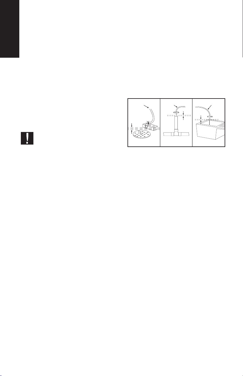
The drain connection, where water from
regeneration will be driven, must be
underneath the installation if possible.
The drain connection must always
have a free outlet. The diameter of this
connection must have a minimum size
of 1”. The maximum distance between
the water softener and the drain intake
cannot be higher than 6m.
Drain pipe Drain pipe Drain pipe
Subterranean drainage Feed pipe Sink outlet
4 cm
aeration
4 cm
aeration
Raising the drain intake above the water
softener level is not recommended, since
it can aect the brine suction and, thus,
impair the regeneration process.
In the event that this is deemed essential,
it can be raised a maximum of 1.5m,
provided that the inlet pressure is higher
than 4 bar.
If the height is greater or there is
not enough pressure, contact your
distributor. Under no circumstances
should the equipment be
installed outdoors. The environment
where the equipment is to be installed
should adhere to any appropriate
hygiene and sanitation conditions.
Avoid any external dripping liquids
from pipes, wastewater, etc. onto the
equipment.
Should softened water be supplied to a
hot water or vapour generator, it will be
necessary to install a dependable check
valve between the water softener and
the generator, in order to prevent hot
water from returning to the system and
damaging it.
The existing pipelines must not have
deposits of either iron or limescale.
Replace all pipelines containing a great
amount of iron or limescale deposits.

11
User’s Manual
In the event that pipelines are blocked
with iron, install a separate iron filter unit
before the water softener.
It is recommended valves are installed
to take samples for both treated and
untreated water, as close as possible to
the water softener.
If there are quick-closing valves, it is
recommended to install a device to
prevent water hammers.
PRECAUTIONS:
1. Reading and review: Carefully read all
procedures, guides and regulations
before installing and using the Ergo
water softening equipment.
2. Treatment of chemicals: Avoid the
presence of flammable products or
materials as a safety measure for
preventing the risks of explosion and
fire. Make sure to use the glue and the
cleaning product for PVC in a well-
ventilated area.
3. Eye protection: Wear safety goggles
during the installation process to
prevent any injury in your eyes,
caused by the ejection of welding
materials or metal and plastic chips.
4. Welding: Use adequate protective
equipment to protect the exposed
surfaces against the flame of the gun
or an excessive temperature increase.
Only use welding guns WITHOUT
LEAD.
5. Grounding: When installing a plastic
pipe between two metallic pipes, a
grounding cable must be installed to
prevent the interruption of grounding
continuity.
6. Easy reach: Use a ladder for working at
heights which are out of reach. If you
must work at heights for a prolonged
period of time, use adequate safety
devices.
Note: We recommend that the
installation is carried out by a qualified
installer. Failure to install the equipment
in accordance with this manual will
render the Limited Warranty void.
If daytime pressure is higher than 5.5
bars, night-time pressure may exceed
the maximum. Please use a pressure-
reducing valve if necessary (a pressure-
reducing valve may reduce the flow).
Note: The Limited Warranty of the
equipment does not cover any damages
due to the freezing of the equipment.
If you have questions about the Ergo
water equipment or if you think that it
is not working properly, contact your
distributor.
5.3 START-UP AND MAINTENANCE
The system must be periodically
sanitised. See ‘Section 8’ for further
information. Maintenance should be
carried out by qualified technicians who
work under the appropriate hygienic
conditions. (For further information
contact your installer.)
6. EQUIPMENT
INSTALLATION
The installation of the water softener
must be carried out by skilled technical
personnel. Follow the recommendations
in ‘Section 5’.
Given that the system that you are going
to install improves the quality of the water
you consume and is considered a food,
all of the tools that you are going to use
for the assembly and installation must
be clean and, under no circumstances,
contaminated or impregnated with
grease, oils or rust. Please be extremely
careful when handling the materials that
are going to be in contact with treated
or untreated water.
(For further information, please contact
your distributor.)
User’s Manual
12
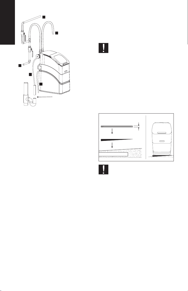
1
2
3
4
5
Provides an air gap for all
drainage lines. See page 11
for further information.
The installation of the equipment should
be carried out in this order:
A. System configuration.
B. Pipe connection.
C. Start-up of the system.
1. Water to be treated.
2. Soft water towards the house.
3. Drain tube.
4. Water to be treated.
5. Overflow line.
Note: This configuration is a typical
installation for the Ergo. Your
installation may dier. Install a pressure
regulating valve and a check valve, when
necessary, in the water supply of the
softener. The by-pass may be installed
with the connections either upwards or
downwards, whilst respecting the inlet
and outlet connections towards the
head, which have embossed marks.
1. The system must always be installed
with the supplied by-pass valve.
Additionally, a three-valve by-pass
can be installed.
2. Close the general water supply valve,
which should be next to the main
pump or the water-meter.
3. Open all taps in order to empty the
pipes from all water.
Note: Make sure that the heater is
not emptied, in order to prevent any
damage.
‘DANGER’. There is a danger of
injury due to an excess of weight. It
is necessary that at least two people
move and install the system, as well as
move and rise the salt bags. There is a
danger of back injuries and other body
injuries.
4. Move the water softener towards the
installation location. Place it on an
even surface. If necessary, place it on
a plywood platform with a minimum
thickness of 2cm. Then, level the
platform using a wedge.
Minimum
depth of 2cm
Plywood
Wedge to level the platform
Installation surface
Plywood
‘WARNING’. Do not place the
wedges directly underneath the
salt tank. The weight of the tank filled
with water and salt may cause the tank
to break against the wedge.
5. First make a visual check and clean
the inlet and outlet connections of the
softener to remove any residues.
6. Assemble the by-pass in the body of
the valve by previously lubricating all
joints with the lubricant supplied.
7. The tubes and accessories used to
connect the main supply pipe to the
inlet and outlet of the water softener
valve must be loosely measured,
cut and assembled. Please keep all
fastenings, joints and tubes centred
and straight. Check that water flows
from the pipe towards the inlet of the
water softener.

13
User’s Manual
Once the installation of all pipes is
finished and before connecting the by-
pass, let water flow through the inlet and
outlet pipes to remove all residues and
check the tightness of the installation.
Note: The inlet and outlet are indicated
in the valve. Draw the sense of the flow
to be sure.
‘WARNING’ Check that the pipes
are fixed, aligned and supported in
order to avoid any pressures on the inlet
and outlet of the water softener. A
wrong pressure coming from a
misaligned pipe, or not supported, could
damage the valve.
WELDED COPPER
1. Clean carefully and apply welding
paste on all joints.
2. Carry out all the welding.
Note: Do not weld to the installation
the pipes of the by-pass valve. The heat
from the welding could damage the
valve.
THREADED PIPE
1. Apply a sealing paste for pipes or Teflon
tape on all male threaded pipes.
2. Tighten all threaded connections.
CPVC PLASTIC PIPE
1. Clean, prepare and glue all joints
according to the manufacturer’s
instructions.
OTHER
Please follow the instructions from the
pipes’ manufacturer when using other
types of pipes and fixtures approved for
drinking water.
6.2 INSTALLATION OF THE DRAIN
AND THE OVERFLOW.
Take the drain tubes towards the
discharge point. Connect the 1/2” tube
to the drain elbow of the valve (2). The
drain tube must penetrate into the elbow
about 18mm (3).
Take the tube towards the drain of the
installation. The section towards the
drain must be as straight as possible to
avoid bottlenecks or syphonage. The
drain must be evacuated in a sump or
drainage outlet with a suitable aeration
to prevent waste water from returning
to the equipment. In the event that the
drain tube must be raised, it can be raised
a maximum of 1.5 metres, provided that
the minimum inlet pressure is 4 bar.
The drain tube must bend around the
Ergo valve anti-clockwise (see previous
figure). Failure to comply with these
instructions may result in damages in
the drain pipe and your new Ergo water
softener.
3
2Drain tube
7. ERGO PROGRAMMER
1. Hardness adjustment knob.
2. Meter dial.
3. Regeneration activator.
4. Viewer for programming.
First, check that the hardness indicator
arrow is located in the round viewer (see
previous diagram). Otherwise, rotate
the inner dial for a full turn (see Manual
Regeneration further on).
1
2
3
4
User’s Manual
14
How to configure hardness:
To ensure a correct functioning of the
water softener, the inlet water hardness
must be configured in the equipment.
Using the hardness adjustment knob,
turn the hardness dial. The configured
value will be that matching the indicator
arrow. The hardness configuration tables
below indicate the equivalence of the
dierent types of hardness (see ‘Tables
for the adjustment of the hardness
regulator’ in page 8). It is recommended
to apply a ‘safety margin’ in the
configured hardness so the equipment
can adapt to the possible fluctuations
that there may be (e.g. if 27ºHF are
measured, 30ºHF must be configured).
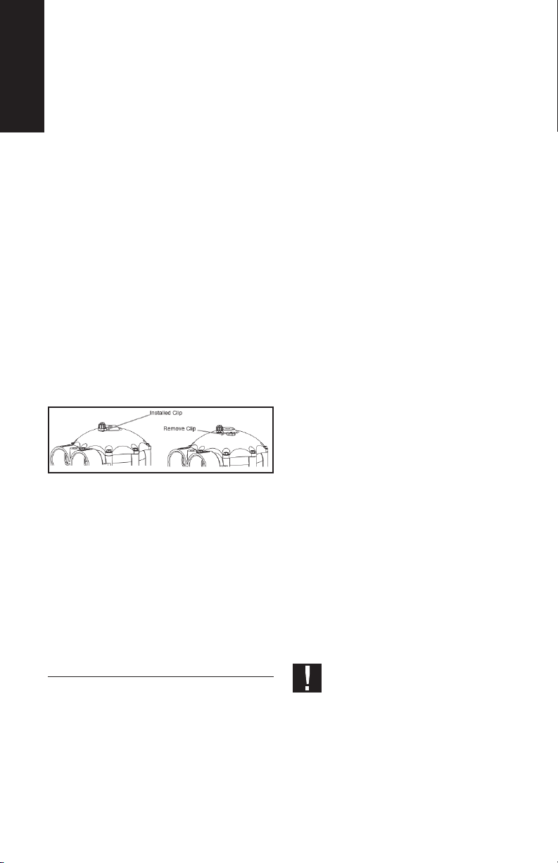
NOTE: The hardness adjustment knob is
protected by a blue plastic locking clip
to prevent any tampering or misuse.
To configure hardness, remove the
locking clip. Once hardness has been
configured, put the locking clip back
on its place.
7.1. MANUAL REGENERATION.
Using a no. 2Phillips screwdriver, press
firmly the regeneration activator of
the water softener and turn it slowly
clockwise until you hear the four clicks
to initiate the regeneration. At this point,
the flow of water inside the equipment
should be audible. If you cannot hear
water moving through the system, maybe
the dial has not advanced enough.
8. HYDRAULIC START-UP
Before starting the system up, please
check that all steps prior to installation,
assembly and programming have been
properly followed, according to this
instructions’ manual, as well as the
regulations in force. To start the system
up, please follow the instructions below:
Do not charge the system with salt
until the end of the start-up. In order to
prevent any air pressure on the water
softener and the pipes, please follow
these instructions in order.
1. Keep the by-pass valve in the “by-
pass” position.
2. Fully open two or more cold and
treated water taps located near the
water softener.
3. Start a manual regeneration as stated
in section ‘Manual regeneration’.
4. Slowly open the by-pass to allow the
entrance of water inside the system.
Keep the by-pass partially open. At
this point, the inlet flow must be
rather low, since in this position water
will come in from the bottom of the
bottle and move upwards to the drain.
5. When water starts flowing
continuously through the drain, fully
open the water inlet of the system.
At this point, the bottle will be full of
water and so a higher flow will not
produce any damage. Water going
out to the drain may be a bit yellowish
or brown. This is completely normal,
since it is due to the preservatives of
the resin.
6. After a few minutes, you will notice
an increase of the water flow towards
the drain. This means that the system
is in the washing position. Let the
equipment finish the process. After
a few minutes, cut the flow of water
towards the drain and refill the brine
tank.
7. Leave the equipment in this position
until water stops flowing in. At this
point, the water level should be
approx. 7-10cm above the bottom of
the tank.
IMPORTANT: Check the tightness
of the brine line, and make sure
that there are no leaks and that the
refilling process has come to a halt.
Note: Since air accumulates inside the
equipment, it is possible that at this
point the equipment might be blocking
the brine level float, which would end the
washing without refilling the brine tank.
If this occurs, repeat the previous steps.

15
User’s Manual
8. Start another regeneration as
indicated in the previous section.
Check that the water level in the
salt tank goes down during the first
minutes of the regeneration. This
means that the brine suction process
is being carried out properly. Let the
regeneration end.
‘WARNING’ It is essential to check
that the brine suction is being
carried out properly, since an incorrect
or insucient suction will aect the
equipment performance and the quality
of treated water.
9. Charge the brine tank with salt.
10.The system is ready to operate.
‘WARNING’ There is a danger of
injury due to an excess of weight. It
is necessary that at least two persons
move and rise the salt bags. There is a
danger of back injuries and other body
injuries.
9. BY-PASS AND MIXING
12
1. Service position: blue.
2. By-pass position: red.
3. Fully closed.
4. Fully open.
As mentioned in “Section 2.7”, it is not
recommended to supply completely
softened water to household supplies.
In order to modify the residual hardness,
slightly open the regulating valve, as
indicated in the images below.
Then measure the water hardness
present on the outlet of the system
and check that it fits within the desired
values. Otherwise, adjust the regulator
and check again.
34
‘WARNING’ The hardness regulator
is supplied in the closed position,
therefore, if the system is not adjusted, it
will supply fully softened water.
10. MAINTENANCE
AND SANITATION
In order to guarantee the proper
operation of the system, the following
verifications must be carried out as
frequently as indicated:
Verification Period
Check the salt level in the tank Monthly
Check entry hardness Monthly
Check treated water hardness Monthly
Sanitation Yearly
Cleaning of the salt tank Yearly
Technical service verification Yearly
It is very important to carry out
the sanitation and descaling tasks
separately, since the chemical products
used for this purpose could have a bad
reaction when mixed. The sanitation
and descaling tasks must be carried
out by turns, according to the indicated
frequency.
Salt refilling:
The salt level in the tank must be
frequently checked. The minimum salt
level must be kept, which corresponds
to the half of the tank volume. If salt
runs down before filling it up again, the
system will produce hard water. After
the verification, check that the salt cover
is properly closed.
Note: For humid areas, it is
recommended to keep a lower salt
level, filling it up more frequently.
Only use salt manufactured for use in
water softeners. The use of block salt
is not recommended. DO NOT USE
User’s Manual
16
ROCK OR GRANULAR SALT in your
system. They contain impurities that can
interfere with performance and could
invalidate the Limited Warranty.
How to break a salt bridge:
Sometimes it is possible that a salt
bridge builds up inside the salt tank.
This is due to a high level of humidity
or to the use of an inappropriate salt.
When there is a salt bridge, there is an
empty space left between water and salt
which prevents it from dissolving. This
means that the water softener will not
regenerate properly and so, it will supply
hard water.
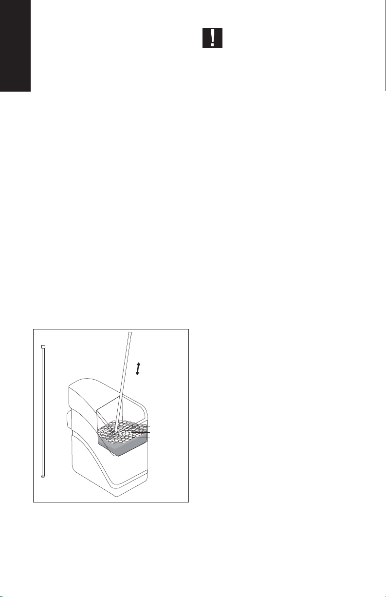
If the tank is full of salt it is difficult to
know whether there is a salt bridge, since
the salt on the surface may seem loose,
even if the lower part is solid. In order to
check the existence of a salt bridge, take
a long rigid tool (e.g. a broom handle)
and keep it next to the water softener to
measure the distance from the floor up
to the salt edge. Then put the tool in the
salt. If there is a hard object, it may be a
salt bridge.
Carefully apply some pressure on several
places until it breaks.
Press
Tool
Press
Salt bridge
Water level
‘WARNING’ Do not use sharp or
pointed objects, since they could
damage the water softener tank.
Sanitation: It is recommended to carry
out a sanitizing process once per year, as
indicated below:
1. Open the cover of the salt tank and
pour between 20 to 30 ml (2or 3
caps) of household, unscented bleach
inside the brine chimney. Close it
again.
2. Check that the by-pass valve is in
service.
3. The disinfection process will be
carried out after the regeneration and
the disinfecting solution will be sent
to the drain.
Anti-scaling: A full regeneration must
be started if the water softener has been
out of service for more than 96h.
If the equipment will not be used for
a long time (holidays, second homes,
etc.), it is recommended to carry out a
full regeneration process before putting
it back into service (according to the
instructions of this manual).

17
User’s Manual
11. FREQUENTLY
ASKED QUESTIONS
The water pressure at home has
dropped. Why has this happened?
A drop in water pressure may indicate
that it is time to change the pre-filter.
If your equipment does not have a pre-
filter, or if you have replaced the filter,
but the problem persists, contact your
distributor.
It seems that the frequency of
regenerations has increased. Is this
normal?
Keep in mind that your equipment
is demand-driven, therefore, it
automatically adapts to your water
consumption. If you believe that your
water consumption has not increased
due to the presence of more people
in the house, additional laundry or
any other reason, please contact your
distributor.
My water does not seem soft to me.
How can I be sure that my equipment is
regenerating properly?
Make sure there is no by-pass in the
water supply of the water softener.
Follow the instructions from page 14
to manually regenerate the tanks of
the water softener. If the equipment
does not automatically move to the
next regeneration, please contact your
distributor to receive further assistance.
I can hear my equipment running or
carrying out the regeneration during
daytime. My previous softener only
worked at night. Is this normal?
Unlike traditional water softeners, this
equipment is demand-driven in function
of water consumption. It has no timers or
electronic components. Therefore, your
equipment regenerates when necessary,
at any time.
How will I know when to add salt?
Lift the cover of the tank to check the
salt level. If you can see water, then you
need to add salt. You can always add salt
if there is enough space to allocate more
salt tablets.
Can I drink soft water?
Yes, soft water is suitable for drinking and
cooking. If the water softener carries out
the regeneration with sodium chloride
(salt), keep in mind that soft water will
include a small amount of added sodium.
If you are following a low-sodium diet,
please take into account the addition of
sodium in water in the total amount of
mineral intake.
If, at any stage, you think that your
equipment is not working correctly,
activate the by-pass mode of the
equipment and contact your installer.

User’s Manual
18
MAINTENANCE COMPLETE
REPAIR
SANITATION
OTHERS
/ /
/ /
/ /
/ /
MAINTENANCE COMPLETE
REPAIR
SANITATION
OTHERS
/ /
/ /
/ /
/ /
MAINTENANCE COMPLETE
REPAIR
SANITATION
OTHERS
/ /
/ /
/ /
/ /
MAINTENANCE COMPLETE
REPAIR
SANITATION
OTHERS
/ /
/ /
/ /
/ /
MAINTENANCE COMPLETE
REPAIR
SANITATION
OTHERS
/ /
/ /
/ /
/ /
TYPE OF SERVICEDATE NAME, SIGNATURE AND
STAMP OF AUTHORISED TECHNICIAN
MAINTENANCE COMPLETE
REPAIR
SANITATION
OTHERS
/ /
INITIAL OPERATION
/ /
/ /
/ /
/ /
TECHNICIAN
ORDINARY
EXTRAORDINARY
WARRANTY
STAMP
TECHNICIAN ORDINARY
EXTRAORDINARY
WARRANTY
STAMP
TECHNICIAN ORDINARY
EXTRAORDINARY
WARRANTY
STAMP
TECHNICIAN ORDINARY
EXTRAORDINARY
WARRANTY
STAMP
TECHNICIAN ORDINARY
EXTRAORDINARY
WARRANTY
STAMP
TECHNICIAN ORDINARY
EXTRAORDINARY
WARRANTY
STAMP
12. SERVICE BOOK: USER
19
User’s Manual
MAINTENANCE COMPLETE
REPAIR
SANITATION
OTHERS
/ /
/ /
/ /
/ /
MAINTENANCE COMPLETE
REPAIR
SANITATION
OTHERS
/ /
/ /
/ /
/ /
MAINTENANCE COMPLETE
REPAIR
SANITATION
OTHERS
/ /
/ /
/ /
/ /
MAINTENANCE COMPLETE
REPAIR
SANITATION
OTHERS
/ /
/ /
/ /
/ /
MAINTENANCE COMPLETE
REPAIR
SANITATION
OTHERS
/ /
/ /
/ /
/ /
TYPE OF SERVICEDATE NAME, SIGNATURE AND
STAMP OF AUTHORISED TECHNICIAN
MAINTENANCE COMPLETE
REPAIR
SANITATION
OTHERS
/ /
INITIAL OPERATION
/ /
/ /
/ /
/ /
TECHNICIAN
ORDINARY
EXTRAORDINARY
WARRANTY
STAMP
TECHNICIAN ORDINARY
EXTRAORDINARY
WARRANTY
STAMP
TECHNICIAN ORDINARY
EXTRAORDINARY
WARRANTY
STAMP
TECHNICIAN ORDINARY
EXTRAORDINARY
WARRANTY
STAMP
TECHNICIAN ORDINARY
EXTRAORDINARY
WARRANTY
STAMP
TECHNICIAN ORDINARY
EXTRAORDINARY
WARRANTY
STAMP
20
Manuel d’utilisation
1. PRÉSENTATION
L’appareil de traitement de l’eau ERGO que
vous avez acheté est un adoucisseur d’eau
à contre-courant hydraulique à hautes
performances qui fournira une eau adoucie
de grande qualité à toute la famille.
Le calcaire ou la dureté de l’eau peut
poser des problèmes à vos canalisations
et empêcher les appareils du réseau
de fonctionner correctement, ce qui
augmente les travaux d’entretien et
réduit leur durée de vie.
Partant de ce constat, nous avons
conçu cette gamme de produits
d’adoucissement de l’eau sanitaire,
spécialement conçue pour protéger la
plomberie de votre maison contre les
eets de l’entartrage.
Grâce à l’adoucisseur d’eau ERGO, vous
et votre famille profitez des bénéfices et
avantages suivants:
• Économies d’énergie.
• Bien-être augmenté.
• Durée de vie de vos appareils
électroménagers renforcée.
• Économies : la consommation de
lessives, adoucissants et produits
chimiques est réduite.
• Faible coût d’entretien.
• Contrôle automatique de l’équipement.
Vous devez impérativement lire et
conserver ce manuel avant
l’installation et le démarrage du système.
Si vous avez toute question quant à
l’utilisation ou à l’entretien de ce système,
veuillez contacter votre installateur.
1,1. SÉCURITÉ DE L’ADOUCISSEUR
D’EAU
Votre sécurité et celle des autres est
capitale. Nous avons inclus des messages
de sécurité dans ce manuel.
Voici le symbole utilisé en cas
d’alerte de sécurité. Ce symbole
vous avertit des situations dans lesquelles
vous ou votre entourage courez un risque
potentiel.
Tous les messages de sécurité seront
accompagnés d’un symbole d’alerte ou
du mot «DANGER» ou «ATTENTION».
Portée de ce manuel:
• DANGER : Risque de mort ou de
blessure grave si les consignes
suivantes ne sont pas immédiatement
suivies.
• ATTENTION : Tous messages de
sécurité fournissant des informations
sur les dangers possibles, sur la façon
de réduire le risque de blessure et sur
ce qu’il est susceptible d’arriver si les
consignes ne sont pas suivies.
1,2. MESURES PRÉALABLES
A L’INSTALLATION
Consultez la «Section 5» avant d’installer
l’adoucisseur d’eau. Suivez attentivement
les instructions (la garantie limitée peut
être tenue pour nulle en cas d’installation
inadéquate). Veuillez lire l’intégralité du
manuel avant de commencer l’installation.
Ensuite, rassemblez le matériel et les
outils nécessaires.
Contrôlez votre plomberie.
L’ensemble des installations doivent être
conformes aux lois en vigueur dans toute
région ou pays. Manipulez l’adoucisseur
d’eau avec soin. Ne le renversez pas, ne le
faites pas tomber et ne le placez pas sur
des objets tranchants. Il est strictement
interdit d’installer l’adoucisseur d’eau
à l’extérieur, car il doit rester à l’abri de
la lumière du soleil et des conditions
climatiques diciles.
2. INTRODUCTION
Nos systèmes sont livrés de série avec un
régulateur de dureté résiduelle, afin de
sélectionner la dureté appropriée à votre
logement. La commande hydraulique
simple permet une programmation facile
et rapide en quelques secondes.
MANUEL
D’UTILISATION
POUR LES ADOUCISSEURS D’EAU
This manual suits for next models
1
Table of contents
Languages:
Popular Water Dispenser manuals by other brands

GE
GE GXCFI5HWW owner's manual

NATURA
NATURA NWSBU2 SER.4 Installation and maintenance guide

elysator
elysator PUROTAP Compenso Series Installation Function Operation Service

Whirlpool
Whirlpool WHES20 Installation and operation manual

Honeywell
Honeywell KaltecSoft KS30E Series installation instructions

Alphacool
Alphacool GPX-N 1660Ti M01 manual


Elkay
Elkay EWCA8 1L Series Installation, care & use manual

BRIO
BRIO Moderna CLPOU730UVRO4 user manual

First Sales
First Sales FS Series Installation instructions and owner's manual

Philips
Philips Micro Pure WP3911 Specifications

Quality Water For Less
Quality Water For Less Fleck 2510 installation guide

WaterLogic
WaterLogic WL3 Firewall Technical manual