Quality Water For Less Fleck 2510 User manual

v1.0
FLECK 2510
METERED WATER SOFTENER
›InstallatIon GuIde

PAGE 2 QualityWaterForLess.com Help: 888-426-5001
›Preface
Thank you for your purchase of a new water softener with Fleck 2510 SXT Meter Control Valve from
QualityWaterForLess.com! We have put together these instructions as reference and to be used as
general installation guidelines.
It is always recommended that a licensed plumber perform all instal-
lation work according to all local codes.
We at QualityWaterForLess.com cannot assume responsibil-
ity for improper installation, application, or injury or damage as a result of improper installation.

PAGE 3Help: 888-426-5001 QualityWaterForLess.com
›table of contents
Page 2 Preface (Click to Jump to Page)
Page 3 Table of Contents
Page 4 Meter Control Valve Ports and SXT Electronic Programming Reference
Page 5 Mechanical Programming Reference
Page 6 Calculating your Hardness Level, and Salt Grid Table
Page 7 Tank Size, Salt Setting, and Salt Grid Table
Page 8 Pre-Installation and Filling the Tank
Page 9 Installing the Fleck 2510 SXT Valve onto the Tank
Page 10 Plumbing the Fleck 2510 SXT Valve into your Home
Page 11 Making the Brine Tank Connection
Page 13 Making the Drain Connection
Page 14 Programming: Entering Master Programming Mode and Initial Programming
Page 15 Programming: Number of Tanks, Capacity, Hardness, and Reserve Capacity
Page 16 Programming: Day Override, Regeneration Time, Backwash, Brine Draw, Rapid
Rinse, and Brine Fill
Page 17 Programming: Meter Type and Resetting the Time
Page 18 Initial System Start-Up and Testing for Leaks

PAGE 4 QualityWaterForLess.com Help: 888-426-5001
›General reference
Please take a moment to review this page in order to
familiarize yourself with these four ports on the valve
and the programming values below. It is crucial not to
mistake the inlet port with the outlet port. Mistaking
and reversing the inlet and outlet ports will lead to fail-
ure of your softener system.
As you work through this guide, please make sure
to follow all instructions exactly and to make special
note of the bolded instructions and warning symbols.
PDF viewers may click underlined text to jump to
that page or the page number in the bottom corner
of every page to jump to the table of contents. All
our installation guides may be found on our site under
“Information.”
›QuIck start
To the right are the program settings for your soften-
er.
If not all of the values are filled in, you can
calculate the missing values from the exercise on
pages 6 and 7 of this guide.
There we will cover
identifying the 3 essential values of
H - HARDNESS
,
C - UNIT CAPACITY
, and
BF - BRINE FILL
. The
remaining values that are already filled in are general
standards for all softener sizes and hardness levels.
MASTER PROGRAMMING MODE:
To enter in/
check the adjacent values of your system, follow
these steps: With either the up or down arrow
button, change the clock to 12:01 PM, set the time
by clicking the left-most CYCLE / REGEN button,
and then hold both the up and down arrow buttons
for 5 seconds to enter master programming mode.
Change values with the arrow buttons and set each
value and advance to the next setting by clicking the
CYCLE / REGEN button.
A more in-depth guide to programming the Fleck
2510 SXT is provided beginning on
page 14
.
outlet
Inlet
brIne
draIn
settInG InPut Value
DF - Display Format GAL - Gallons
VT - Valve Type dF1b
CT - Control Type Fd - Flow Delayed
NT - Number of Tanks 1
C - UNIT CAPACITY ,000 Grains
H - HARDNESS Grains per Gallon
RS - Reserve Selection SF
SF - Safety Factor 15%
DO - Day Override 14 Days
RT - Regen Time 2:00 AM
BW - Backwash 10 Minutes
BD - Brine Draw 60 Minutes
RR - Rapid Rinse 12 Minutes
BF - BRINE FILL Minutes
FM - Flow Meter Type t0.7 or P0.7
Job Number:
Model Number:
Mineral Tank Size:
FM - Flow Meter Type
t0.7 P0.7

PAGE 5Help: 888-426-5001 QualityWaterForLess.com
›MecHanIcal ProGraM
If you have a mechanical meter valve, here are your
softener program settings.
If you have an SXT valve,
refer to page 4 for your programming values.
If not
all of the values to the right are filled in, you can
calcu-
late the missing values below AND with the exer-
cise on pages 6 and 7 of this guide.
The remaining
values that are already filled in are general standards for
all softener sizes and hardness levels.
settInG InPut Value
GC - GAL CAPACITY
00 Gallons
BW - Backwash 10 Minutes, 5 Pins
BD - Brine Draw 60 Minutes, 30 Slots
RR - Rapid Rinse 12 Minutes, 6 Pins
BF - BRINE FILL
Minutes, Slots
fIGure 5-a
fIGure 5-b
The
GC - GALLON CAPACITY
equates
to the
C - UNIT CAPACITY
divided
by the
H - HARDNESS
minus
15% of the result (Ex: 64K tank / 28 gpg hardness =
2,286 gal; 2,286 gal - 343 = 1,943 gal capacity.
Unit Ca-
pacity and Hardness can be determined from pages
6 and 7
). If the result exceeds the highest number on
the dial, use the next smallest
Unit Capacity
listed on
the table on page 7
. With the front cover off of your
control valve and while looking at the panel on the right
side, pull out and rotate the dial and line up your gallon
capacity with the white dot (Figure 5-A).
Swing open the right panel with the capacity wheel to
the right to reveal the Program Wheel on the opposite
side of the panel (Figure 5-B). To set the regeneration
cycle times with the above input values, place the pins
in the slots surrounding the wheel.
Each slot/pin on
the Program Wheel represents 2 minutes during the
regeneration process.
fIGure 5-c
backwasH
brIn e draw
raPId rInse
brIne fIll
fIGure 5-b
1.
The first
group
of pins represents the BW - Backwash
duration; 5 pins for 10 minutes (Figure 5-C).
2.
The next
span of empty slots
represents the
BD - Brine Draw duration; 30 empty slots for 60 minutes.
3.
The next
group
of pins represents the RR - Rapid
Rinse duration; 6 pins for 12 minutes.
4.
The next
span
of empty slots represents the
BF - BRINE FILL
duration
found on page 7
.
If it calls
for an odd number of minutes, round up for the appro-
priate number of pins (Ex: 15 min 16 min 8 pins).
5.
The last
group
of 2 pins marks the end of regeneration.

PAGE 6 QualityWaterForLess.com Help: 888-426-5001
PPM Hardness ÷17.1 = gpg Hardness before Iron
1 ›calculatInG Your Hardness leVel
1)
Water Test: Before start-up, it is crucial that you know your water’s HARDNESS and IRON levels in
order to set up your unit properly.
If your unit is not programmed with your particular hardness level, it will
either regenerate too early or too late. If you do not know your water hardness or iron levels, you can take a
sample of your untreated water to a local pool shop, hardware store, or well driller
(city water has no iron)
2)
Initial Hardness:
Your Hardness test results may be recorded in Grains per Gallon (gpg), Parts per Million
(PPM), or Milligrams per Liter (mg/L). Note that
PPM and mg/L are the same measure
and both figures can
be used interchangeably.
If you get a hardness level in PPM or mg/L, please divide this number by 17.1
to get Grains (gpg).
Ex: If your hardness is measured at 300 PPM, take 300 / 17.1 = 18 gpg before iron
3)
H - COMPENSATED HARDNESS:
Your Iron results should also be measured in either PPM or mg/L.
Take
your level of iron multiplied by 5 and add it to the hardness level from the previous step.
This final figure
will be your
Compensated Hardness Level
that we will program into your softener system. Ex: If your iron level
is measured at 2 PPM, add 2 x 5 = 10 Grains of hardness to existing hardness total. 18 + 10 = 28 Grains Total
4)
The compensated hardness level you just calculated will be the “H” value you use to program your
softener. You may record this in the table on page 4 or 5.
Depending on your compensated hardness
level, you will be able to use a different salt setting for programming and running your softener unit. The
lower the hardness level, the more efficient you will be able to be with salt consumption for regeneration
PlaIn
GrId
11x11” G r I d 15x17” Gr Id 18” dIaMeter GrId
GrId +
3” leGs
GrId +
6” leGs
gpg Hardness + ( PPM Iron x 5 ) = gpg H - COMPENSATED HARDNESS

PAGE 7Help: 888-426-5001 QualityWaterForLess.com
5)
C - UNIT CAPACITY:
In the first column, identify the
section
containing your softener tank size and then within this
section, find the
row
pertaining to your
H - Compensated Hardness
level. Then look under the
C - Capacity
column
to find the most efficient program value to enter for your
C - Unit Capacity
and record it
in the table on page 4 or 5.
Note that your unit capacity program value may actually be lower than the tank’s rated capacity.
This is to
accommodate a lower salt dose for regeneration.
6)
BF - BRINE FILL:
In the first column, identify the
section
containing your softener tank size and then within this
section, find the
row
pertaining to your
H - Compensated Hardness
level. Then look under the
BF - Brine Fill
column
to find the most efficient program value to enter for your
BF - Brine Fill
and record it
in the table on page 4 or 5.
7)
Example:
If you ordered a 64K grain capacity system and have 28 gpg compensated hardness, you would look under
the 64K, 2.0 cu ft section and then look under the 25+ gpg row for your particular programming values. Note that the
11x11” and the 15x17” brine tanks are too small for the amount of brine needed to regenerate a 64K grain capacity system
with 25+ gpg hardness. According to the table you would opt for an 18” diameter brine tank with a grid plus 6” legs
Tank Size
H
HARDNESS
C
CAPACITY
BF
BRINE FILL
lbs of Salt 11x11” G r i d 15x17” Grid 18x33” Grid 18x40” Grid 24x41” Grid 24x50” Grid
24K
0.75 cu ft
8x44”
0 - 12 gpg 15K 3 Min 4.5 lbs Grid NO GRID NO GRID NO GRID
TOO
LARGE
TOO
LARGE
12 - 25 gpg 20K 5 Min 7.5 lbs Grid Grid NO GRID NO GRID
25+ gpg 24K 7 Min 11.25 lbs Grid + 3” Legs Grid Grid Grid
32K
1.0 cu ft
9x48”
0 - 12 gpg 20K 4 Min 6 lbs Grid NO GRID NO GRID NO GRID
TOO
LARGE
TOO
LARGE
12 - 25 gpg 27K 7 Min 10 lbs Grid + 3” Legs Grid Grid Grid
25+ gpg 32K 10 Min 15 lbs Grid + 6” Legs Grid + 3” Legs Grid Grid
40K
1.25 cu ft
10x44”
0 - 12 gpg 25K 5 Min 7.5 lbs Grid Grid NO GRID NO GRID
TOO
LARGE
TOO
LARGE
12 - 25 gpg 34K 9 Min 12.5 lbs Grid + 3” Legs Grid Grid Grid
25+ gpg 40K 13 Min 18.75 lbs TOO SMALL Grid + 3” Legs Grid + 3” Legs Grid + 3” Legs
48K
1.5 cu ft
10x48”
0 - 12 gpg 30K 7 Min 9 lbs Grid + 3” Legs Grid Grid Grid
TOO
LARGE
TOO
LARGE
12 - 25 gpg 41K 10 Min 15 lbs Grid + 6” Legs Grid + 3” Legs Grid Grid
25+ gpg 48K 15 Min 22.5 lbs TOO SMALL Grid + 6” Legs Grid + 3” Legs Grid + 3” Legs
64K
2.0 cu ft
12x52”
0 - 12 gpg 40K 8 Min 12 lbs Grid + 3” Legs Grid Grid Grid
Grid +
5” Legs
Grid +
5” Legs
12 - 25 gpg 54K 14 Min 20 lbs TOO SMALL Grid + 6” Legs Grid + 3” Legs Grid + 3” Legs
25+ gpg 64K 20 Min 30 lbs TOO SMALL TOO SMALL Grid + 6” Legs Grid + 6” Legs
80K
2.5 cu ft
13x54”
0 - 12 gpg 50K 10 Min 15 lbs Grid + 6” Legs Grid + 3” Legs Grid Grid
Grid +
5” Legs
Grid +
5” Legs
12 - 25 gpg 68K 17 Min 25 lbs TOO SMALL Grid + 6” Legs Grid + 3” Legs Grid + 3” Legs
25+ gpg 80K 25 Min 37.5 lbs TOO SMALL TOO SMALL TOO SMALL Grid + 6” Legs
96K
3.0 cu ft
14x65”
0 - 12 gpg 60K 12 Min 18 lbs TOO SMALL Grid + 3” Legs Grid + 3” Legs Grid + 3” Legs
Grid +
6” Legs
Grid +
6” Legs
12 - 25 gpg 81K 20 Min 30 lbs TOO SMALL TOO SMALL Grid + 6” Legs Grid + 6” Legs
25+ gpg 96K 30 Min 45 lbs TOO SMALL TOO SMALL TOO SMALL TOO SMALL
120K
4.0 cu ft
16x65”
0 - 12 gpg 80K 16 Min 24 lbs TOO SMALL Grid + 6” Legs Grid + 3” Legs Grid + 3” Legs
Grid +
8” Legs
Grid +
8” Legs
12 - 25 gpg 108K 27 Min 40 lbs TOO SMALL TOO SMALL TOO SMALL TOO SMALL
25+ gpg 120K 40 Min 60 lbs TOO SMALL TOO SMALL TOO SMALL TOO SMALL

PAGE 8 QualityWaterForLess.com Help: 888-426-5001
2 ›PlacInG and fIllInG tHe tank
1) Choose the final location for your water softener
tank and place the tank upright and level on the
surface. Filling the tank may be necessary on
some systems. Your tank may have also come
pre-filled, and in this case you only need to un-
screw the protective cap as shown in
Figure 8-A
2)
If your tank is not filled
, place the riser tube
into the tank as shown in
Figure 8-B
. Please
make sure that the riser tube seats into the
bottom of the tank and that the top of the tube is
flush with the top of the tank opening
fIGure 8-a fIGure 8-b
›Pre-InstallatIon
Before assembly of your new system, be sure that the following conditions have been met for the place-
ment of your system:
• Level, firm surface, such as concrete, on which
to place the softener tank and salt tank (also
known as a
brine
tank)
• Un-switched power source, standard US plug,
120v 60hz (the softener system includes a
5 ft power cord and plug)
• Access to the water main coming into your
home. You will need to install the softener at
this point to assure that water for the home is
going through the system
• Nearby floor drain or standpipe to connect to the
softener for use during each regeneration
Well
Pump or
City
Meter
Water
Heater
Bypass
Bath Sink Toilet Kitchen
SpigotSpigot
Softener
Drain Line
Hard Water
Soft Water
Overflow
(Optional)
Floor
Drain

PAGE 9Help: 888-426-5001 QualityWaterForLess.com
3) Before filling the tank, place a piece of painter’s
tape over the top of the riser to prevent resin
from dropping down inside the riser tube as
shown in
Figure 9-A. iAvoid using duct
tape which leaves behind unwanted residue
4) Place the included filling funnel over the top of
the tank as shown in
Figure 9-B
and prepare to
fill the tank. If your softener system came with
gravel
, please pour this into the tank
first
, then
pour in the included resin media afterwards
fIGure 9-a fIGure 9-b
3 ›InstallInG tHe fleck 2510 sxt ValVe
1) Remove the filling funnel and tape and while
using the included silicone lubricant packet, lu-
bricate the inner and outer o-rings on the bottom
of the Fleck 2510 SXT Meter Valve as shown in
Figures 9-C and 9-D
2) Next, install the
top screen (standard OR fine
mesh)
to the bottom of the Fleck 2510 SXT Meter
Valve as seen in Figure 9-E and then place the
valve onto the top of the tank, being sure that the
riser tube fits into the central o-ring on the valve,
as shown in Figure 9-F.
Hand-tighten
the valve to
the tank.
Do not use Teflon tape or pipe dope
on the valve or tank threading
fIGure 9-c fIGure 9-e
fIGure 9-d fIGure 9-f
sta n dard
fIne MesH

PAGE 10 QualityWaterForLess.com Help: 888-426-5001
4 ›PluMbInG Your fleck 2510 sxt ValVe
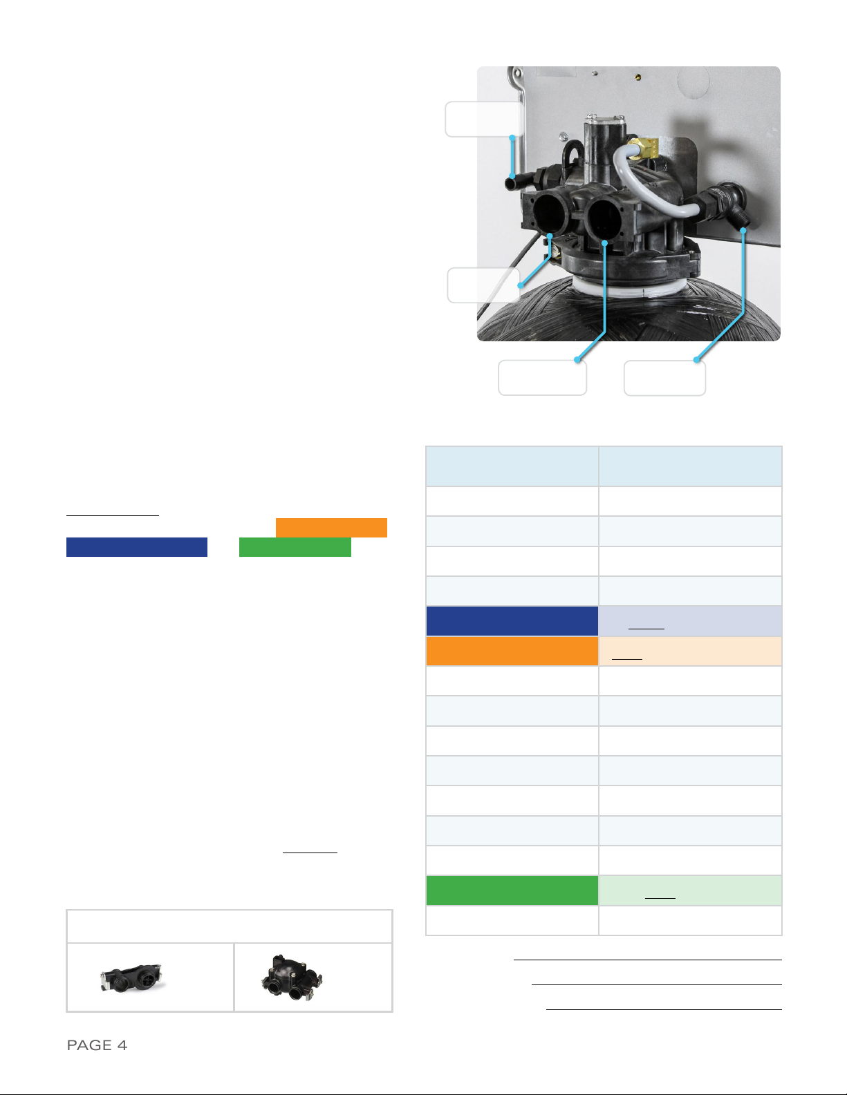
1) Before beginning your installation, please first fa-
miliarize yourself with the IN and OUT ports on the
Fleck 2510 SXT Meter Valve.
In order to prevent
damage to your home and to the softener
system, install the softener according to the
IN and OUT arrows on the softener valve
2) Locate the main shut-off valve for your house
and turn it to the OFF position. If you have a
private well, this valve should be near your well
pressure tank. If you have a city water supply,
your valve should be near your water meter
3) Depressurize and drain your home of water by
turning on all faucets and fixtures in your home,
including those outside
4) Pick your installation point and cut a section of
pipe out to run to and from your softener.
In
most cases it is preferred to keep outside
lines UNSOFTENED. If you wish to keep
your outside lines unsoftened, you must
plumb BYPASS lines to run hard water to
these fixtures
5) Using soldered copper, PVC plastic pipe, or flex-
ible connections, plumb the system according to
all local plumbing codes.
If using copper pipe,
please pre-fabricate at least a 12” section
of pipe for the IN and OUT bound lines and
use a wet rag on the lines being soldered to
prevent heat damage during soldering
6) Once all connections have been made, place the
system into bypass by either using your existing
3-valve bypass (if ordered with a YOKE adap-
tor), or by switching your included bypass ON (if
ordered with a bypass)
7) Next, gradually open your main valve and allow
all air in your plumbing lines to escape slowly.
Also, you may turn off all outside and inside
faucets and fixtures
8) Check for leaks at your plumbing site for signs
of slow drips and rectify if necessary.
Please do
NOT take the softener out of BYPASS as the
installation is not completed yet. Please take
this opportunity to check and re-check the IN
and OUT ports to make sure they are correct
fIGure 10-c
5) Assemble the plumbing adaptor to the valve as
shown in Figure 10-C (your bypass/plumbing
adapter model may vary). When assembling
the clips back onto the valve, leave the first clip
loose, tighten the second clip, and complete the
assembly by tightening the first clip. i
Please
lightly tighten the screws into the meter as
overtightening will easily cause cracking
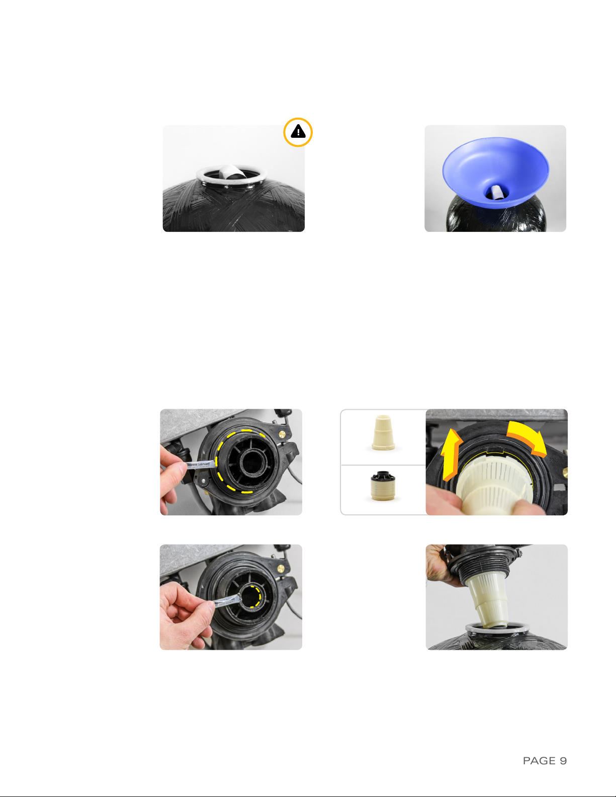
3) Locate the plumbing adapter that was shipped
with your system and disassemble the plumbing
adaptor clips as shown in Figure 10-A
4) Using the included silicone lubricant packet, lu-
bricate the o-rings on the Fleck 2510 SXT Meter
Valve as shown in Figure 10-B
fIGure 10-a fIGure 10-b

PA G E 11Help: 888-426-5001 QualityWaterForLess.com
5 ›MakInG tHe brIne tank connectIon
1) Attach the brine nut, tapered ferrule, metal tube
insert, and brine line screen to one end of the
included brine tubing as shown in Figure 11-A.
i
Be sure that the tapered side of the black
ferrule faces away from the end of the brine
line and that the tapered side of the white
ferrule faces towards the end of the brine line
2) Next, connect this prepared end of the tubing
to the Fleck 2510 SXT Meter Valve as shown in
Figure 11-B. Tighten the nut to the valve using
a wrench until snugly in place. Be careful not to
over tighten, as you may sever the brine line
3) Locate the brine well and remove the cap.
You
may also take this moment to prepare and
insert the brine support grid determined
from pages 6 and 7
. Then pull the
474 Brine
Float Assembly
out of the brine well as shown
in Figure 11-C
4) Next, fix the 474 Brine Float Assembly to the
brine well through the pre-drilled hole and
hand-tighten as shown in Figure 11-D
fIGure 11-a fIGure 11-b
fIGure 11-c
fIGure 11-e
fIGure 11-d
fIGure 11-f
5) Take the other end of your brine line tube, make
sure this end is clean cut, recut if it is not clean,
mark 3/4” from the end of the tube, and insert the
tube through the small hole drilled through the brine
tank and brine well (Figure 11-E)
6) Firmly insert the tubing end 3/4” into the tube
opening on the 474 Brine Float Assembly as
shown in Figure 11-F. i
Make sure the tube is
fully inserted into the assembly

PAGE 12 QualityWaterForLess.com Help: 888-426-5001
7) If you ever need to remove the tube, evenly press on
both sides of the grey ring surrounding the tube and
pull out as shown in Figure 12-A. i
Be sure to recut
the end of the tube each time you remove it to
ensure a proper seal when the tube is inserted
8) Finally, use ½” inner diameter (I.D.) tubing to connect
the drain barb fitting on the brine tank to a floor drain
as shown in Figure 12-B. Note that this is not neces-
sary as the 474 assembly is designed to prevent an
overflow from occuring, but it is a good precaution
fIGure 12-a fIGure 12-b

PAGE 13Help: 888-426-5001 QualityWaterForLess.com
fIGure 13-a
fIGure 13-e fIGure 13-f
fIGure 13-d
fIGure 13-b
fIGure 13-c
6 ›draIn connectIon
1) Locate the barbed fitting and use Teflon tape to
wrap the threading as shown in Figure 13-A.
Be
careful to wrap the tape clockwise with the
threading towards you.
Attach the barbed fit-
ting to the DLFC fitting and i
Please use cau-
tion not to over tighten the barbed fitting
2) Move to the rear of the Fleck 2510 SXT control
valve, find the drain fitting pin and remove it to
allow you to insert the DLFC/barbed drain fitting
as seen in Figure 13-B
3) Insert the DLFC/Barbed fitting as seen in Figure
13-C.
Be sure that the fitting is fully inserted
into the drain port by clicking it into place
4) Reinsert the drain fitting pin to lock the DLFC/
barbed drain fitting into the Fleck 2510 SXT con-
trol valve as seen in Figure 13-D
5) Next, assemble your ½” I.D. drain line to the drain
barb as shown in Figure 13-E.
Be sure to use rigid
wall ½” I.D. tubing that will not flatten.
Wrap
electrical tape over the drain tubing to prevent a tube
split and clamp the tubing securely into place with the
included blue clamp as shown in Figure 13-F
6) Connect the other end of this drain line tubing se-
curely to a standpipe or drain in accordance with all
local plumbing codes.
Be sure that the drain line
is securely in place before putting your softener
in service. During regeneration, there will be
increased flow via this tubing which may cause
the tubing to become loose

PAGE 14 QualityWaterForLess.com Help: 888-426-5001
fIGure 14-a fIGure 14-b
fIGure 14-c fIGure 14-d
7 ›ProGraMMInG tHe fleck 2510 sxt ValVe
1) Loosen the screw on the front of the valve and
remove the valve front cover to expose the SXT
controller and prepare for programming as seen
in Figure 14-A
2) To begin programming, first plug in your
2510SXT Valve to a nearby wall outlet. The
system will illuminate 4 digits. The system will
show the time of day and the amount of gallons
remaining before the next regneration. This
display will switch between these values about
every 10 seconds
3) Set the time on the system to 12:01 PM by
pressing either the UP or DOWN button as
shown in Figure 14-B. i
Be careful to confirm
the presence of the PM symbol in the top
right corner.
You may hold the button to allow
the time to scroll faster. Once the time display is
set to 12:01 PM, press the REGEN button once
as shown in Figure 14-C
4) To enter MASTER PROGRAMMING MODE,
press the UP and DOWN buttons TOGETHER
and HOLD both for 5 seconds as shown in
Figure 14-D
fIGure 14-e fIGure 14-f
5) The display should now show
DF / GAL
as shown
in Figure 14-E. This indicates U.S. Operational
Mode measuring consumption in gallons.
Do
not change this value and press the REGEN
button once to advance to the next setting
6) The display should now show
VT / dF1b
as
shown in Figure 14-F. This indicates Regeneration
Flow Downflow Single Backwash. Do not change
this value and press the REGEN button to advance
to the next setting

PAGE 15Help: 888-426-5001 QualityWaterForLess.com
fIGure 15-a
fIGure 15-c
fIGure 15-b
fIGure 15-d
7) The display should now show
CT / Fd
as shown
in Figure 15-A. This indicates Control Type Meter
Delayed Mode. Do not change this value and press
the REGEN button to advance to the next setting
8) The display should now show
NT / ---1
as shown
in Figure 15-B. This indicates the number of tanks
is one. Do not change this value and press the
REGEN button to advance to the next setting
9) The display should now show
C / 32.0
. This
indicates the Capacity is 32,000 grains. i
Use
the UP or DOWN button to change this
value to the one listed on page 4/calculated
on pages 6 and 7
and press the REGEN button
as shown in Figure 15-C
10) The display should now show
H / 20
. This
indicates the Hardness is 20 gpg. i
Use the
UP or DOWN button to change this value to
the total hardness level of your water listed
on page 4/calculated on pages 6 and 7
and
press the REGEN button as shown in Figure 15-D
11) The display should now show
RS / SF
as shown
in Figure 15-E. This indicates that the Reserve
Selection is Safety Factor percentage. Do not
change this value and press the REGEN button
to advance to the next setting
12) The display should now show
SF / 10
. This indi-
cates the Safety Factor is 10%. This means the
system will leave 10% of the softening capacity
for the day before regeneration.
Use the UP
button to change the value to 15%
and press
the REGEN button as shown in Figure 15-F
fIGure 15-e fIGure 15-f

PAGE 16 QualityWaterForLess.com Help: 888-426-5001
17) The display may now show
RR / 12
as shown in
Figure 16-E. This indicates Rapid Rinse time is 12
minutes long. Do not change this value and press
the REGEN button to advance to the next setting
18) The display may now show
BF / 10
. This indi-
cates the length of the Brine Fill cycle during re-
generation. i
Use the value listed on page 4/
calculated on pages 6 and 7
and then use the
UP or DOWN button to adjust this. Then press
REGEN as shown in Figure 16-F
fIGure 16-a
fIGure 16-c
fIGure 16-b
fIGure 16-d
13) The display should now show
DO / 14
as shown
in Figure 16-A. This indicates the Day Override is
14 days; the system will regenerate in 14 days if
the meter has not measured water consumption
to have reached the calculated capacity. Do not
change this value and press the REGEN button
14) The display should now show
RT / 2:00
as
shown in Figure 16-B. This indicates the system
will regenerate at 2:00 AM following the day the
water consumption has passed the calculated
capacity. If you prefer an alternate regeneration
time, please enter it here and then press the
REGEN button to advance
15) The display should now show
BW / 10
as
shown in Figure 16-C. This indicates Backwash
time is 10 minutes long. Do not change this
value and press the REGEN button to advance to
the next setting
16) The display should show
BD / 60
as shown in
Figure 16-D. This indicates Brine Draw time is 60
minutes long. Do not change this value and press
the REGEN button to advance to the next setting
fIGure 16-e fIGure 16-f

PAGE 17Help: 888-426-5001 QualityWaterForLess.com
turbIne
Paddle
fIGure 17-a
fIGure 17-c
fIGure 17-b
19) The display may now show
FM / t0.7
as shown
in Figure 17-A. This indicates Flow Meter type
3/4” Turbine. Set the setting to t0.7 if you have
the 3/4” turbine meter or P0.7 for the 3/4” paddle
wheel meter. Press the REGEN button to ad-
vance to the home screen
20) The system will now exit Master Programming
mode and the display should now show the time
of day followed by the number of gallons remain-
ing. Now change the time of day to your current
time with either the UP or DOWN button.
Be
careful to note the presence or absence of the
PM indicator in the top right corner
. Confirm
the time with the REGEN button (Figure 17-B)
21) Finally, replace the valve cover and tighten the valve
cover screw to cover the valve and finish program-
ming. Make sure the lip of the cover rests on the
shelf of the uncovered valve as you are closing it as
seen in Figure 17-C

PAGE 18 QualityWaterForLess.com Help: 888-426-5001
8 ›InItIal start-uP
1) With one nearby softened faucet running in the COLD position, slowly open your bypass valve or 3-valve
bypass to about ¼ open to allow the air trapped in the softener to escape via your running faucet.
NOTE: Opening the bypass too quickly or too open may damage your softener or plumbing
2) Allow the softener tank to slowly fill with water. After a few minutes, you will see a trickle of water coming
from the cold water faucet. Allow the water to run slowly in this manner for an additional 5 minutes. Next,
with the cold water faucet still running, gradually move your bypass valve to the fully open position.
NOTE: You may see some initial discoloration from the softened water – this is normal and should
dissipate within the first 40-50 gallons of water used.
Turn off the running cold water faucet when the
water runs clear
›c on Gr at u l at Io ns
Your new softener with Fleck 2510 SXT Meter Valve is now properly installed and programmed!
Please maintain your system by keeping the softener plugged-in and always keep your brine tank
filled with salt to at least above the water level. We appreciate your business, and hope that you
enjoy years of trouble-free softened water!
3)
i
To test the integrity of your new system and all connections
,
it is strongly encouraged that you
perform a short form regeneration to check for leaks before service.
Begin this process by adding approxi-
mately 5 gallons of water/the amount of water needed to cover the brine grid into the brine tank
4)
If you have the mechanical version of the Fleck 2510,
begin a regeneration by turning the timer wheel
clockwise, let the regeneration run its full course to completion, and check the entire system for leaks. If you
notice a leak originating from the drain line/connection,
return to page 13
to review preparing the drain con-
nection. If you notice a leak originating from the brine line/connections,
return to pages 11 and 12
to review
preparing the brine tank connection
5)
If you have the electronic Fleck 2510 SXT version,
begin the regeneration sequence by HOLDING the
REGEN button for 5 seconds. Once the screen stops flashing BW, let BW - Backwash run for about 1 minute
to observe the water leave out the drain line and check for leaks. If you notice any leaks,
return to page 13
to
review preparing the drain connection. Click the REGEN button ONCE to move on to BD - Brine Draw
6) Once the screen stops flashing BD, let BD - Brine Draw run for about 1 minute to observe the water level in
the brine tank being drawn lower. Also check the brine line and the float valve in the brine well for leaks. If the
water level doesn’t lower or there is a leak,
return to pages 11 and 12
to review preparing the brine tank
connection. Click the REGEN button ONCE to move on to RR - Rapid Rinse
7) Once the screen stops flashing RR, advance from RR - Rapid Rinse to BF - Brine Fill by clicking the
REGEN button ONCE more. Once the screen stops flashing BF, let BF - Brine Fill run for about 1 minute to
observe the water level in the brine tank rise. Also check the brine line and float valve in the brine well for
leaks. If the water level doesn’t rise or there is a leak,
return to pages 11 and 12
to review preparing the
brine tank connection. Click the REGEN button ONCE to finish
8) Now you may add 120-160 pounds of pellet, solar, or block salt to your brine tank.
Always keep your brine
tank filled with salt to at least above the water level.
You do not need to perform a regeneration im-
mediately after installation as the new resin arrives at full softening capacity. Simply let your softener meter
automatically trigger regenerations by tracking the water consumption
Table of contents
Popular Water Dispenser manuals by other brands

Elkay
Elkay Space-ette With FLEXI-GUARD WD701-8 1G... Installation, care & use manual

Omnifilter
Omnifilter WH10 installation instructions

Aquaport
Aquaport AQP-SFS-IH Installation & operating instructions

Oasis
Oasis MAXXFILL PULSE user guide

Elkay
Elkay EFHFA8 2A Series Installation, care & use manual

Elkay
Elkay EZH2O VRCGRNTLDWS C Series Installation & use manual