Ergomotion quest 4.0 User manual

Actual product appearance and functionality may vary from photographs, illustrations and descriptions included in this manual.
OWNER’S MANUAL
ADJUSTABLE BASE | OWNER'S MANUAL
Actual product appearance and functionality may vary from photographs, illustrations and descriptions included in this manual.

table of contents
Safety Precautions and Usage Statements ....................................................................... 1-3
Parts List ..................................................................................................... 4
Base and Remote Overview .....................................................................................5
Quick Reference Guide ..........................................................................................6
Installation Guide ............................................................................................7-8
Oine Voice Control Puck with Wireless Charger .................................................................9-11
Remote Control .............................................................................................12-13
Remote Control Pairing.........................................................................................14
Connecting Strap .............................................................................................15
Syncing Two Bases.............................................................................................16
Headboard Brackets ...........................................................................................17
Emergency Battery Backup Strap ................................................................................18
Troubleshooting ...............................................................................................19

1
TO REDUCE THE RISK OF SHOCK, BURNS, FIRE OR INJURY:
For optimal safety and operation, plug bed base into a surge protector
(not included). The bed base should only be plugged directly into a wall
outlet or surge protector (strongly recommended). Always unplug the
base from the electrical outlet before servicing any part of the base. To
reduce risk of electric shock, unplug the base before cleaning. To safely
disconnect, ensure the base is in a flat position with all motors o, and
unplug from power source. Keep the power cord away from heated
surfaces. Never operate the base when the air openings are blocked. Keep
air openings free of lint, hair and the like. Do not drop or insert any object
into any opening. Discontinue use of the bed base and contact a qualified
service center if: it has a damaged cord or plug, if it is not working
properly, or it has been dropped into water. Only use this bed base for
its intended use as described in this manual. Do not use accessories/
attachments that are not recommended by the manufacturer. Close
supervision is required when the bed base is used by or near children,
convalescents, disabled persons or pets. Improper connection of the
equipment can result in the risk of electrical shock, electrical fire or faulty
operation of this bed base. If the plug does not fit your outlet, contact a
qualified electrician to install a suitable outlet. Unauthorized modification
or failure to use a wall outlet or surge protector could void the electrical
portion of your warranty.
CHILDREN AND PETS:
Immediately dispose of all packing materials as it may pose a smothering
risk to small children and pets. To avoid injury, it is not advised to allow
children and small pets to play on or under the bed. Children should not
operate the bed base without adult supervision.
SAFETY FEATURES:
Manual operation – If something gets caught in the platform when
flattened, you can manually raise the platform up by lifting at both the head
and foot to relieve pressure and allow for release.
Emergency stop – Stop the motion of the platform by pressing any button
on the remote control.
Power outage – Use the “Emergency Battery Backup Strap” as a temporary
power source to get the base to a desired position. Instructions on how
to operate the Battery Backup Box are on the Emergency Battery Backup
page(s).
PACEMAKERS:
Some products contain Neodymium MAGNETS which may interfere
with devices such as pacemakers, ICD’s and any other device sensitive
to magnetic fields. It is STRONGLY recommended that owners of such
medical devices consult their physician prior to using products that
contain Neodymium MAGNETS. It is also possible that some pacemakers
may falsely interpret the optional massage feature vibrations as
movement/exercise. This is a common occurrence with any product that
creates a vibrating movement and may aect the pacemaker. Please
consult your physician before using the massage feature.
IN-HOME USE AND HOSPITAL STANDARDS:
Ergo adjustable bed bases are designed solely for in-home use. This
base was not designed as a hospital bed and is not designed to meet
hospital standards. Do not use this base with TENT TYPE oxygen therapy
equipment or near explosive gases.
ADDITIONAL SAFETY FEATURES
Casters (optional leg accessory) are equipped with locking wheels to
prevent unwanted movement. Even when locked and unable to roll, it is
possible for the casters to slide. Free release head and foot motors are
designed to lower the mattress by retracting only with gravity, never
pulling downwards, which minimizes pinch points
Attention: Important Safety Disclaimers
Read the following information before using this product. Failure to use a surge protection device could
compromise safety or cause product malfunction and could void the electrical portion of your warranty.
safety precautions and usage statements

2
LIFTING/LOWERING MECHANISMS
The lift/lower feature will emit a minimal humming sound during
operation. This is normal. During operation, the lift arm wheels make
contact with the platform support of the base. This contact may result in
metal on metal or metal on plastic contact. This applies slight tension on
the moving components and resonance is reduced to a minimum level. If
excessive noise or vibration is experienced, reverse the movement action
(up or down) of the base with the remote control. This should realign
the base’s activating mechanisms to the proper operational position. In
normal base operation, the wheels, which allow the bed to maintain its
distance from the wall, will make contact with the steel platform supports
of the base creating a contact noise. When entering, exiting or shifting
weight on the base, this contact noise may be audible as the wheels make
contact. This is normal.
MATERIALS
Ergo adjustable bases are constructed from various materials including
woods, metals, plastics and fabrics. Tension, pressure or movement
applied to the frame, platform or shroud through general use may create
an audible sound.
MASSAGE OPERATION AND LOCATION ENVIRONMENT
The massage feature will emit a tone during operation. This is normal.
As the massage intensity level is increased, the tone will intensify. The
volume of this tone is directly related to the location environment.
For example, when demonstrated in a show room, the surrounding
environmental noise will cover some of the massage noise. However,
when installed in a home setting with wooden floors, carpeted or not,
the massage volume will be more noticeable. To minimize this resonance,
place a piece of carpet, or rubber caster cups, under each leg or caster of
the base. It is possible to experience vibration or noise from the exterior
bed frame, headboard brackets, headboards or footboards if mounting
bolts are not firmly tightened.
Levels 1-6 of massage intensity represent the revolutions of the motor
per minute. Level 6 provides the maximum number of RPMs. However,
this does not mean that the feeling of vibration is the strongest.
Depending on the mattress material, thickness, and positioning of the
user, the feeling of vibrations will dier. We encourage the user to find
the massage intensity setting that suits them best. It is important to
understand the physics of vibrations. Just as an engine may run rough
during idle, as the RPMs increase, the vibrations change concurrently.
TOLERANCE
All Ergo adjustable foundations, depending on make and model, are
designed and manufactured to perform and function within designated
quality control parameters. Bases are subject to meticulous and rigorous
inspections during the quality control process to ensure bases will
operate within these standards during normal operating use. Normal
operating use is defined as the following: Adjustable foundation is to
be operated with a mattress and load.
Testing procedures require lifetime cycle
tests with up to 120kg distributed load.
The angle (designated “α” in figure 1)
between the back section and the flat
section for various configurations of the
mattress support platform shall be ± 3°,
which translates to a tolerance of up to 1
½”.
The angle (designated “β” in figure 1) between the flat section and foot
section for various configurations of the mattress support platform shall
be ± 3°, which translates to a tolerance of up to ¾”.
Any adjustable foundation deemed to be within these allocated
tolerances is considered to have met the manufacturer’s quality control
standards.
THAT “NEW PRODUCT” SMELL:
Some people notice a slight odor to their new adjustable base—this can
come from our material manufacturing process. This smell is normal and
usually disappears before the product reaches you. Sometimes, however,
this smell may still be noticeable. It usually disappears after a few weeks,
safety precautions and usage statements
Adjustable
Bed Tolerance
Ergomotion Inc. | ph 1-888-550-3746 | fx 805-979-9399 | www.ergomotion.com
All Ergomotion adjustable foundations, depending on make and model, are designed and manufactured to perform and
function within designated quality control parameters. Bases are subject to meticulous and rigorous inspections during
the quality control process to ensure bases will operate within these standards during normal operating use.
Normal operating use is defined as the following:
-Adjustable foundation is to be operated with a mattress and load. Testing procedures require lifetime cycle
tests with up to 120kg distributed load.
The angle (designated “α” in figure 1) between the back section and the flat section for various configurations of the
mattress support platform shall be ± 3°, which translates to a tolerance of up to 1 ½”.
The angle (designated “β” in figure 1) between the flat section and foot section for various configurations of the mattress
support platform shall be ± 3°, which translates to a tolerance of up to ¾”.
Any adjustable foundation deemed to be within these allocated tolerances is considered to have met the manufacturer’s
quality control standards.
(α°)
(β°)
When operating a "paired" split base setup there may be a time latency up to 1.5 seconds between each bases articulation.
Blake Pettit
Quality Assurance Manager
Ph 805-979-3875
Fx 805-979-9399
www.ergomotion.com

3
providing adequate ventilation of the product and the environment.
BREAK IN PERIOD:
You can speed up the break-in period by simply spending time in the
adjustable bed through activities such as reading, watching TV or playing
with the kids or grandkids. The extra movement will help the adjustable
base respond to weight and temperature changes. Some of the materials
in our adjustable bases such as the woods, metals and plastics used in the
platform, frame and components are sensitive to moisture content and
temperature and may make sounds in colder environments.
PAIRED OPERATION:
When operating a “paired” split base setup there may be a time latency
up to 1.5 seconds between each bases articulation.
WEAR AND TEAR:
Wear and tear is damage that naturally and inevitably occurs as a result
of normal use or aging.
FABRIC CARE:
To prolong the life of your fabric, protect from direct sunlight whenever
possible. For spot cleaning, wipe area with a light damp sponge or
vacuum with a soft brush attachment to remove particles. Keep at a
minimum of 30cm (12 inches) away from direct heat sources. For a
deeper cleaning, blot liquid spills with a clean dry cloth. Wipe with a clean
cloth dampened with warm water. Do not wet excessively. A soft bristle
brush may be used to remove ingrained soil. Avoid scratching by gentle
brushing. Wipe with a clean cloth dampened with warm water to remove
residues. Dry in shade away from direct heat. If persistent marks remain
visible after cleaning, seek professional advice.
PRODUCT RATINGS:
The lift motors are not designed to operate continuously for more than
[2] minutes in an [18] minute time period or approximately 10% duty
cycle. Attempting to circumvent or exceed this rating will shorten the
life expectancy of the product and may void the warranty. The massage
motors are not designed to operate continuously for more than 30
minutes at a time. Please allow the massaging system to rest for 30
minutes after automatic massage shut o before restarting.
WEIGHT LIMITS:
This product is not rated to support weights in excess of 750 pounds. The
base will structurally support this weight, provided it is evenly distributed
across the bed base. The adjustable base is not designed to support or
lift this amount in the head or foot sections alone. Exceeding this weight
restriction could damage the bed and/or cause injury and will void the
warranty.
SAVE THESE INSTRUCTIONS.
FCC Compliance:
NOTE: This equipment has been tested and found to comply with
the limits for a Class B digital device, pursuant to part 15 of the FCC
Rules. These limits are designed to provide reasonable protection
against harmful interference in a residential installation. This
equipment generates, uses and can radiate radio frequency energy
and, if not installed and used in accordance with the instructions,
may cause harmful interference to radio communications. However,
there is no guarantee that interference will not occur in a particular
installation. If this equipment does cause harmful interference to
radio or television reception, which can be determined by turning the
equipment o and on, the user is encouraged to try to correct the
interference by one or more of the following measures:
• Reorient or relocate the receiving antenna.
• Increase the separation between the equipment and receiver.
• Connect the equipment into an outlet on a circuit dierent from
that to which the receiver is connected.
• Consult the dealer or an experienced radio/TV technician for help.
safety precautions and usage statements

4
A) B)* C)
D) E) F) ‡
G) H) I) ‡
J)
parts list
All electronics and components that need to be installed are
located in boxes under the base or attached to the frame.
A) Wireless Remote Control (1)
B) Mattress Retainer Bar (1)*
C) Legs (6)
D) Power Cord (1)
E) Power Supply (1)
F) Sync Cord ‡
G) Battery Backup Strap (1)
(2) 9V Batteries (not included)
H) Oine Voice Control Puck with Wireless Charger
I) Connecting Strap‡
Misc Parts (not included):
J) Surge Protector
Headboard Bracket Components (Optional):
K) Headboard Bracket (2)†
L) T-Bracket (2)†
M) Spacer (2)†
N) Long Bolts (8)†
O) Short Bolts (10)†
P) Nuts (18)†
* These items are attached to the base for shipping purposes. Carefully
remove from base and set aside.
‡ Only included in Twin Long and Cal King Split bases.
† This is an optional item and can be purchased (1-888-550-3746)
Before discarding the packing materials - ensure all the parts are accounted for.
HEADBOARD BRACKET COMPONENTS (Optional)
J)†K)†L)†M)†N)†O)†
5
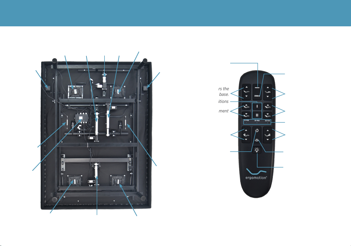
base and remote overview
Head Tilt
Motor
Lumbar
Motor
Massage
Motor Massage
Motor
Underbed
Lighting
Underbed
Lighting
Massage
Motor
Massage
Motor
Head
Motor
USB Ports
Control
Box
USB Ports
Foot
Motor
Lifts & lowers the
head portion of the base.
Memory Preset Positions
Head Tilt Adjustment Lumbar Motor Adjustment
Massage Timer Indicator
Increase & decrease the
foot massage intensity
Turns on head & foot
massage
Underbed Lighting
Increase & decrease the
head massage intensity
Massage Timer/ALL OFF
Lifts & lowers the
foot portion of the base.
Zero-G® Preset Position
Flat Preset Position
6
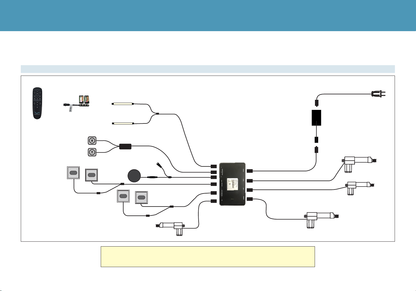
quick reference guide
Not to scale. For illustration purposes only. Read all instructions before beginning installation.
If installing a split unit, see pages 15-16.
Remote Emergency Battery
Backup Strap
Underbed Lighting
Head Motor
Power Cord
Input Cable
Power
Supply
Foot Motor
Lumbar Motor
Splitter
Cable
Head
Massage
Motors
Foot
Massage
Motors
Head Tilt
Motor
USB Ports
USB Charger
Oine
Voice
Control
Puck
Extension
Cord
ELECTRONICS OVERVIEW
7
installation guide
Always use two people when setting up the base.
For customer support, visit www.ergomotion.com or call: 1-888-550-3746
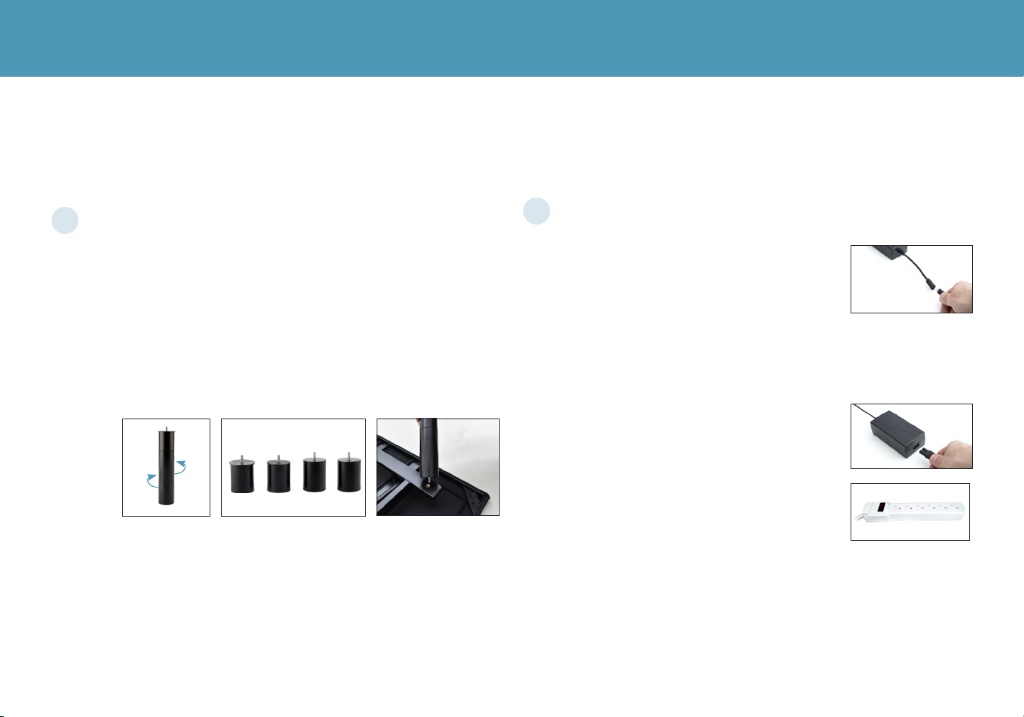
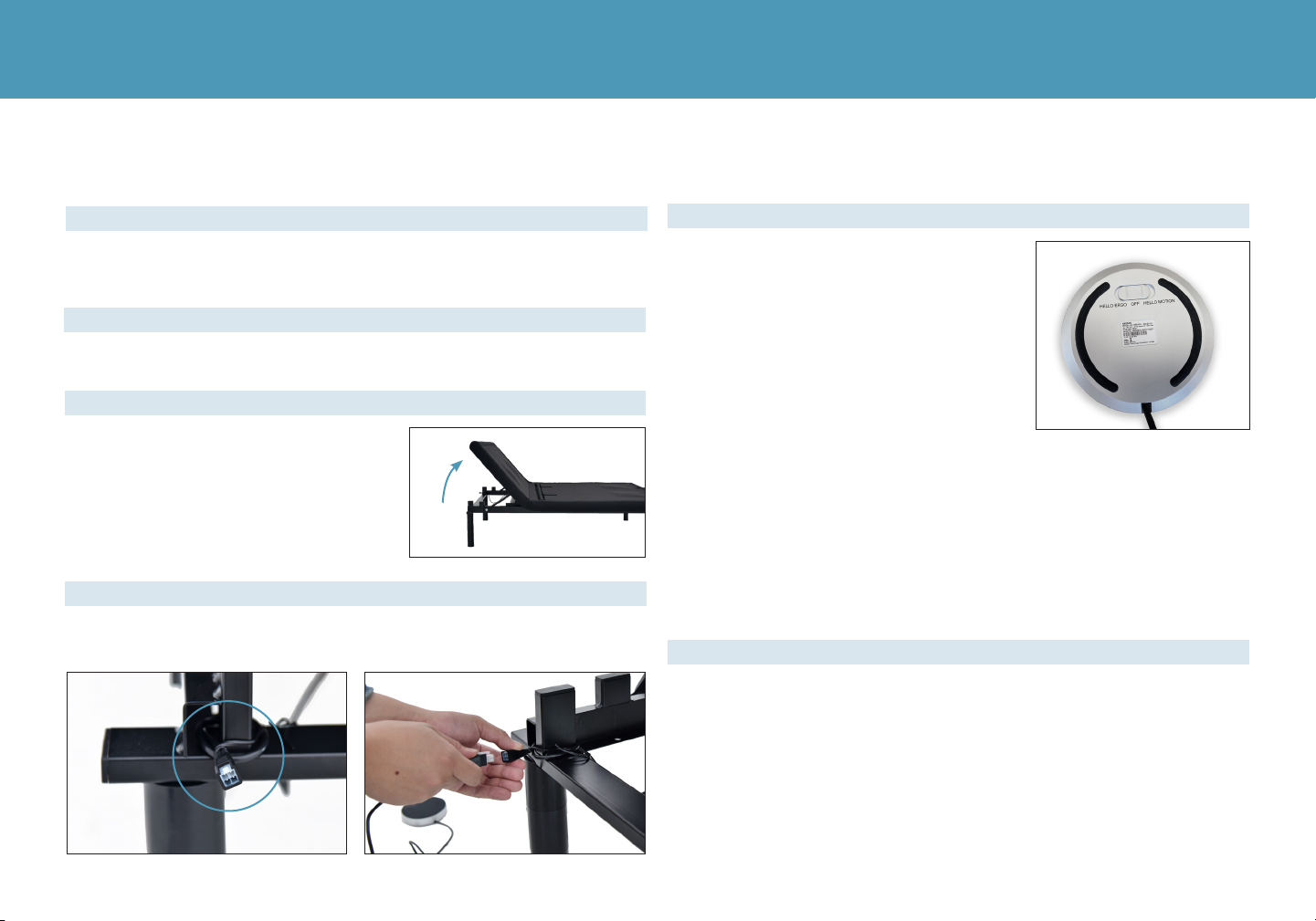
Remove the bed base from the box keeping the bottom of
the base facing upwards.
• Untwist the mattress retainer bar from the frame and set aside.
• Legs are shipped fully assembled. Alternative heights in 3"
increments can be achieved by removing leg segments.
• To install the legs, thread the washer over the bolt of the leg
with the recessed side facing the leg, and tighten by hand.
Do not over tighten.
Flip the base & connect the cables.
• Uncoil the Input Cord (connected to
control box’s Power port) and plug it into
the Power Supply.
• Carefully flip the base over on to its legs.
Important: Two people are required to move the bed base. Do
not drag across the floor. Do not rest frame on its side, excessive
pressure may damage the legs.
• Insert the Power Cord into the Power
Supply.
• Plug the Power Cord into a power outlet.
A surge protector is recommended.
2
1

8
installation guide
For customer support, visit www.ergomotion.com or call: 1-888-550-3746
Test remote functions & install mattress retainer bar.
• Place each end of the mattress retainer bar into the inserts at the
foot of the base until the retainer bar is secured in place.
• Quickly test remote functions to verify proper setup and return
the base to a flat position before placing the mattress on top.
Setup the Oine Voice Control Puck wiht Wireless Charger.
• Follow the instructions on the following pages to setup the
Ofine Voice Control Puck with Wireless Charger device and
start controlling your base with voice commands.
34
9
oine voice control puck with wireless charger
ATTENTION: Your adjustable base can pose an entrapment hazard which
is increased in households with small children and or pets. Using voice
controls further increases this entrapment hazard due to the potential of
unintentionally triggering a command vocally. The voice controls could be
unintentionally triggered by yourself, a small child, the television, a radio
program, etc. and by using this product you agree that you have read
and reviewed the commands, including the Emergency Commands, and
acknowledge the increased entrapment risk associated with using voice
commands.
If you agree with this statement please read the instructions on the following
pages to learn how to setup the Ofine Voice Control Puck, however if you
have any questions in regard to the use of voice controls please contact
customer service prior to activating the Ofine Voice Control Puck.
WIRELESS CHARGER
• Intro: This item has a wireless charging function. The maximum
charging power is 10W. Place the device to be charged in the center
of the wireless charger. During normal operation, the green light will
indicate that it is charging.
• Overheat Protection: In a high temperature environment, when the
internal temperature of the product rises to 158 degrees (F), the
wireless charger will enter a protection mode and the product will
turn off the wireless charging function. When the internal temperature
lowers to below 122 degrees (F), the charging function will resume.
• Incompatible Device Detection: If an incompatible device is placed
on the charger, the red light will indicate that the device should be
removed.
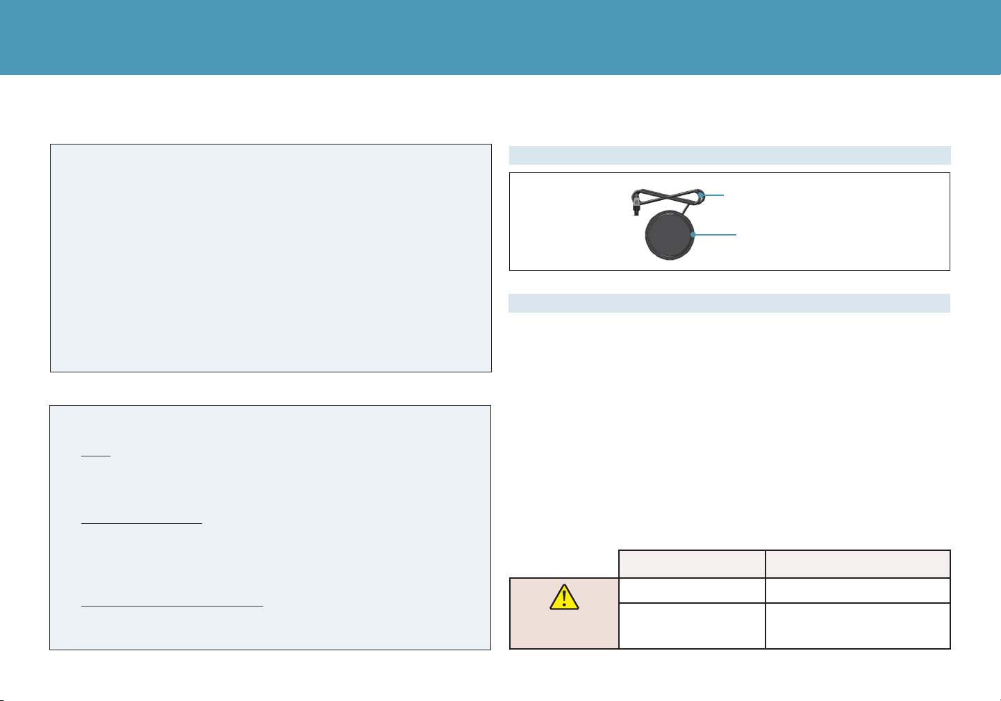
Puck Cable
Puck Voice Control
OVERVIEW
Setup the puck to enable oine voice control of your adjustable base.
• If you wish to stop using voice commands, you can turn the device off by
switching the slider on the back of the Ofine Voice Control Puck to the
middle “OFF” position.
• Your adjustable base can pose an entrapment hazard and there is an
increased risk for households with small children and or pets. Using
voice controls increases this entrapment hazard due to the potential of
accidentally triggering a command vocally. The voice controls could be
unintentionally triggered by a small child, television, radio program, etc.,
please read the “Emergency Commands” section so that you are familiar
with these commands in the event of an emergency.
SAFETY INFORMATION
ENTRAPMENT HAZARD: This bed can crush and kill when it moves. Using
voice controls may increase this risk. Review emergency commands before
activating voice controls.
VOICE COMMAND EXPLANATION
EMERGENCY
COMMANDS
STOP-MOVING Stop all movement
ALL-UP Raise both the head &
Foot 6 seconds
10
To use the Puck Voice Activated System, simply say the invocation
command you chose during setup, either “HELLO ERGO” or “HELLO
MOTION”, and wait 1-2 seconds for the microphone to activate. Once
the microphone is activated, indicated by the blue light, it will be
active for 8 seconds. While the microphone is active you can now use
any of the voice commands listed below to control your adjustable
base. If no command is heard within 8 seconds, the Puck will enter
“sleep mode” and the microphone will be deactivated.
WAKE UP DEVICE
oine voice control puck with wireless charger
Remove The Puck from the box.
Please take a minute to familiarize yourself with the voice commands
listed on the next page.
Use the remote control to lift the
HEAD to the maximum angle.
Locate the connector secured to the corner of the frame and
connect it with the Puck Voice Control plug as shown in the picture.
Step 2
Step 1
Step 3
Step 4
Step 5
Follow the installation steps below to setup The Puck device.
The Puck Voice Control will arrive in the
Off position and you will need to activate
the Puck by selecting an invocation
command of your preference.
Use the slider switch on the back side of
the Puck to select the invocation phrase
you wish to use, either “HELLO ERGO” or
“HELLO MOTION”.
Note: If you have a split base, each side
must have a different invocation phrase
in order to work independently.

11
oine voice control puck voice commands
VOICE COMMAND EXPLANATION VOICE COMMAND EXPLANATION
Common
Instructions
GOOD-NIGHT Flat bed
Massage
Control
TURN-ON-MASSAGE Turn on massage driver
RISE-AND-SHINE Adjust the bed to the preset position for Zero-G® TURN-OFF-MASSAGE Turn off massage driver
TV-TIME Adjust the bed to the preset position for
watching TV
MASSAGE-UP Increase the massage strength
MASSAGE-DOWN Decrease the massage strength
Actuators
Control
RAISE-HEAD Back actuator rises 3S
Head
Massage
TURN-ON-HEAD-MASSAGE Turn on head massage
LOWER-HEAD Back actuator falls 3S HEAD-MASSAGE-UP Increase the head massage strength
RAISE-FOOT Foot actuator rises 3S HEAD-MASSAGE DOWN Decrease the head massage strength
LOWER-FOOT Foot actuator falls 3S
Foot
Massage
TURN-ON-FOOT-MASSAGE Turn on foot massage
RAISE-LUMBAR Lumbar actuator rises 3S FOOT-MASSAGE-UP Increase the foot massage strength
LOWER-LUMBAR Lumbar actuator falls 3S FOOT-MASSAGE-DOWN Decrease the foot massage strength
RAISE TILT Head actuator rises 3S
Massage
Mode
WAVE-ONE Switch to massage mode 1
LOWER TILT Head actuator falls 3S WAVE-TWO Switch to massage mode 2
Preset
FLAT-PRESET Flat bed WAVE-THREE Switch to massage mode 3
ANTI-SNORE Adjust the bed to the preset position for anti-
snore
Save Preset
Position
SAVE-LOUNGE Set the current position to relax mode
ZERO-G®/
ZERO-GRAVITY Adjust the bed to the preset position for Zero-G® SAVE-FAVORITE Set the current position to fovorite mode
LOUNGE-PRESET Adjust the bed to the preset position for relax SAVE-TV Set the current position to watching TV
mode
FAVORITE-PRESET adjust the bed to the preset position for favorite
one Underlight
Control
TURN-OFF-LIGHT Turn off underlight
TV PRESET Adjust the bed to the preset positon for
watching TV TURN-ON-LIGHT Turn on underlight
Once the invocation phrase has been uttered, the microphone will be active for 8 seconds which is indicated by the blue light.
While the microphone is active you can now use any of the command utterances listed below to control your adjustable base.
12
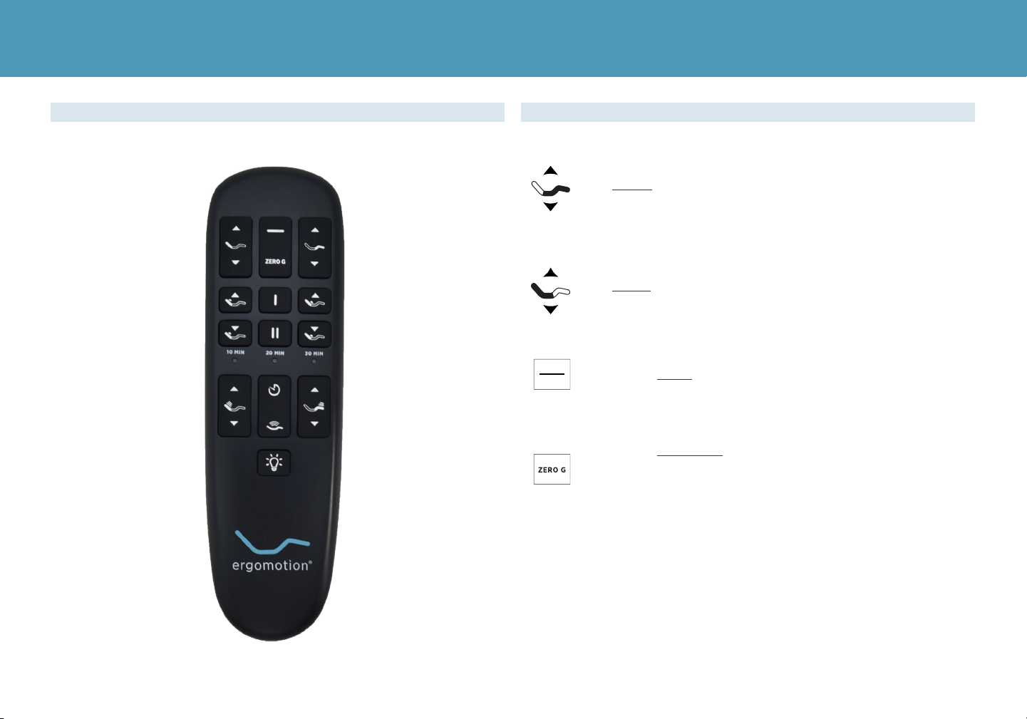
remote control
The HEAD arrows lift and lower the head section of
the base.
The FOOTarrows lift and lower the foot section of
the base.
One touch FLAT preset position.
One touch ZERO-G® preset position. Zero-G® adjusts
your legs to a higher level than your heart helping
to relieve pressure o the lower back and promote
circulation.
ADJUSTREMOTE OVERVIEW

13
The HEAD MASSAGE button will turn on the head
massage. Cycle through 3 massage intensities.
The FOOT MASSAGE button will turn on the foot massage.
Cycle through 3 massage intensities.
The TIMER/ALL OFF button starts massage at level 2.
Select a 10, 20 or 30 minute massage interval. Pressing a
fourth time will turn o massage.
The lights on the top of the remote indicate a 10, 20 or 30
minute timer setting. Massage will automatically shut o
after 10 minutes if the massage timer isn’t set.
The MASSAGE button turns on the head and foot massage.
Press once to activate Underbed Lighting. Press again to
turn o.
Preset Position #1
Preset Position #2
TO PROGRAM THE PRESET POSITIONS:
Articulate the head and foot to your desired
position. Next, press and hold one of the preset
buttons [I, II] for 5 seconds. The position is now
saved.
NOTE: To restore the preset buttons back to
their original factory settings, hold FLAT and
ZERO-G® simultaneously for at least 5 seconds.
The original presets will be restored.
10 MIN
MASSAGE FUNCTIONS / LIGHTING
MEMORY PRESETS
MOTOR FUNCTIONS
remote control
The HEAD TILTarrows will adjust
the level of head support.
The LUMBARarrows will adjust
the level of lumbar support.
14
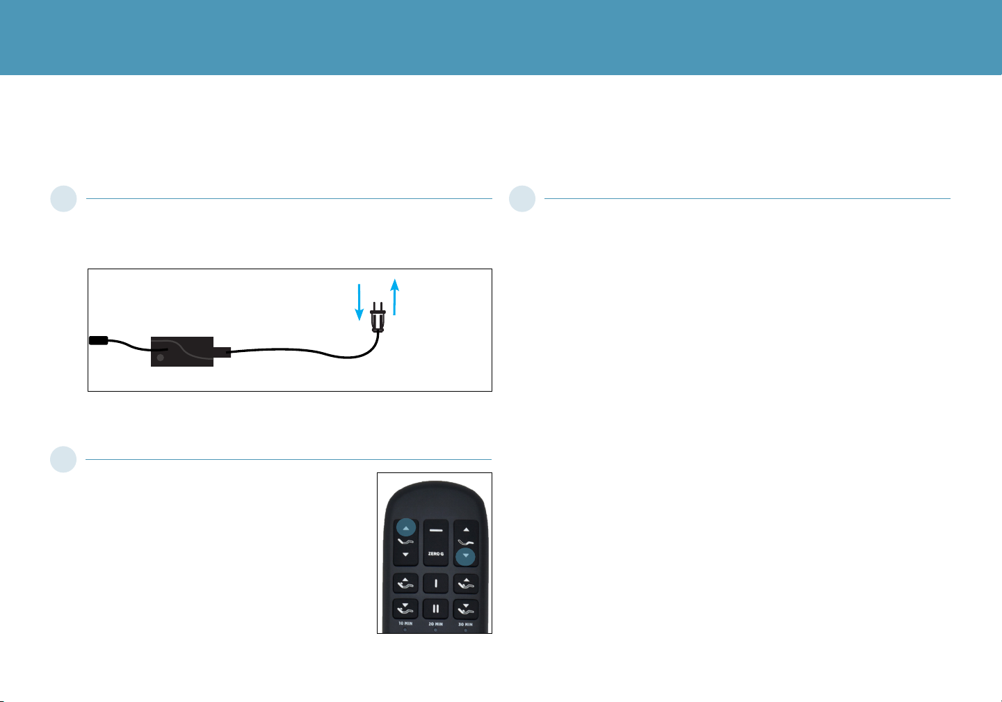
The original remote that comes in the box is already paired to the adjustable base. No further action is required. In
the event that the remote is not paired with the base, follow the steps below.
Unplug the Power Cord from your power outlet. Wait 1 minute, then
plug it back in to your power outlet. Perform Step 2 within 10 seconds,
while the control box light is flashing.
pairing remote control
Press and hold down the Head Up and Foot
Down buttons simultaneously. The LED light
on the remote will start flashing. When the
LED stops flashing, the illuminated light on the
Control Box will go out. Release the Head Up
and Foot Down buttons. The remote is now
paired to the adjustable base.
Test all remote functions. If the remote buttons do not impact the
adjustable base movements, please repeat the process again or call
Ergomotion customer service: 1-888-550-3746
Power Cord
Power Supply
1 3
2
15
With the bases in their desired
location, slightly loosen both legs
to allow the strap to fit on the leg
bolt, between the leg washer and
frame.
Slide side (a) of the connecting strap onto leg bolt. Swing the strap
and connect side (b) to the leg bolt. Secure the strap by shifting to
the left.
Re-tighten legs. Do not over tighten. Use the remaining strap and
repeat on other end of the base.
connecting strap (not included)
ab
If a split setup is being installed, optional plastic connecting straps can be used to help secure the bases
together. To purchase optional accessories, please call 1-888-550-3746.
2
3
1

16
syncing two bases (optional)
Sync Cord
Control Box 1 Control Box 2
A Sync Cord is included with the base. Not available on Queen, Full or Full-Long size bases.
The Sync Cord connects the two control boxes to a single remote for the synchronization of two bases.
This process is most commonly used for syncing two connected TXL bases.
Unplug bases from power source.
Connect the Sync Cord to the Multifunction port of each Control
Box.
Plug bases back into the power source.
Check to ensure all cords are securely attached. Both remotes will
now operate both bases simultaneously. If bases become mismatched, returning the bases to the flat positions will
re-sync the mechanical positions.
PERFORMANCE NOTES
The system is now linked. Pressed buttons on either
remote will control the two bases simultaneously.
1
2
4
3

17
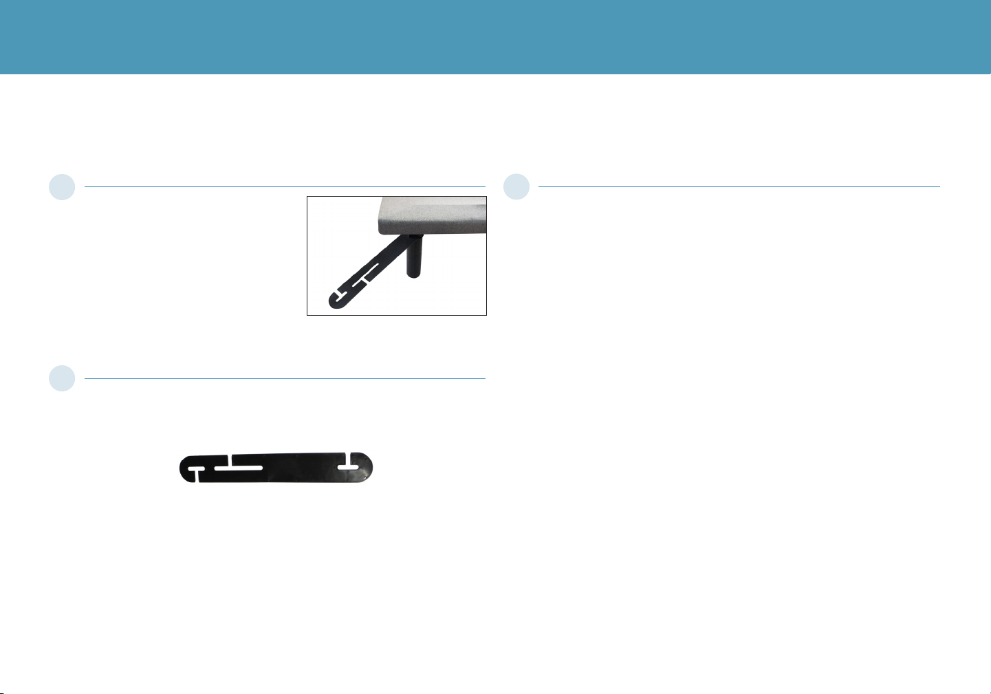
headboard bracket installation guide (optional)
a.) Align the hole in the bracket to the brass sleeve into which the
leg threads. Hold the bracket in place and screw the leg into the
base until it is snug. DO NOT OVERTIGHTEN. Too much force may
cause the leg to spin freely.
b.) Align the tab with the hole in the frame (located towards the foot
of the base) and use a short bolt and nut to secure the bracket.
Make sure the bolt is tight.
Headboard Brackets are an optional accessory.
A 9/16” (14 mm) & 1/2” (13 mm) socket and crescent wrench are necessary to complete installation.
Attach the plastic spacer and T-Bracket.
a.) Measure the distance between the mounting holes on the
headboard and install the spacer and attachment plate to
accommodate the headboard.
b.) To install the plastic spacer and attachment plate, you will need
(2) long bolts and (2) nuts. Place the spacer and attachment plate
in the desired location and slip the bolts through the holes with
the head of the bolt facing outward. Position the bolts diagonally
on the spacer. Use the 9/16” socket and wrench to tighten the
bolts.
You may now connect your headboard to the attachment plates
using the remaining short bolts and nuts to secure it to the brackets.
The heads of the bolts will face outward. Use a 9/16" socket and 1/2"
wrench to tighten the bolts.
2
3
1
18
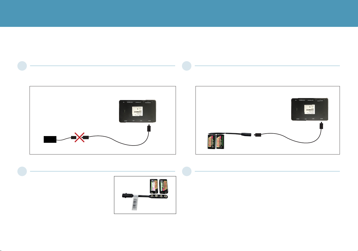
battery backup strap (optional)
For emergency use only, in case of a power outage.
Batteries are not to be used for normal operation of the bed.
Disconnect the Power Supply from the input power cord.
Note: Detach the Battery Backup Strap and reconnect the power
supply after the emergency is over, as the system will continue to
draw power from the batteries even if not in use.
Connect the end of the Battery Backup Strap to the input power cord
that is attached to the control box.
Use the remote to return the base to a flat position.
Control Box
Control Box
Input Cord
Input Cord Battery Backup Strap
Power Supply
Connect the Battery Backup Strap to
the (2) Alkaline 9 Volt batteries. Do
not mix brand name Batteries.
1 3
42
Table of contents
Other Ergomotion Medical Equipment manuals

Popular Medical Equipment manuals by other brands


Physio Control
Physio Control HeartStart MRx user guide

Unomedical
Unomedical comfort Instructions for use

Siemens
Siemens MULTIMOBIL 10 installation instructions

Ossur
Ossur MIAMI J SELECT Instructions for use

Aquilosports
Aquilosports Aquilo Instruction guide

Kyoto Kagaku
Kyoto Kagaku NCPR Simulator Plus instruction manual