Ergosante Technologie HAPO V1 User manual

HAPO V1
Instruction manual
Date : 07/04/2020

INSTRUCTIONS
Doc. N°
Rev. 1 Sheet 2 of
36
Title:
1. TABLE OF CONTENTS
2. IDENTIFICATION 3
2.1 Reference documents 3
3. ABBREVIATIONS AND DEFINITIONS 3
4. GENERAL PRESENTATION 3
4.1 Equipment identification 3
4.2 Manufacturer 4
4.3 Qualification of personnel 4
4.4 Pictogram convention 4
4.5 Limitation of supply 5
5. GENERAL DESCRIPTION 5
5.1 Main characteristics 5
5.2 Overall dimensions 5
5.3 Operation 5
5.4 Diagram 6
5.5 Use Cases 7
6. MODE OF OPERATION 9
6.1 Installation and preparation 9
6.2 Use 9
6.3 Transport 22
6.4 Storage 22
6.5 Duration of use 23
7. CONTRAINDICATIONS 23
8. RESIDUAL RISKS 24
9. MAINTENANCE 24
9.1 Cleaning and maintenance 24
9.2 DISASSEMBLY OF THE HAPO FOR CLEANING 24
9.3 REINSTALLING THE HAPO after cleaning 29
9.4 General maintenance 33
9.5 Maintenance plan 33
10. INCIDENTS 34
10.1 Instructions in case of problems 34
11. SCRAPPING 34
12. LEGAL INFORMATION 34
13. RESPONSIBILITY 34
The manufacturer is only liable if the product is used in accordance with the descriptions and instructions in this document
(operating instructions). The manufacturer accepts no liability for damage resulting from non-observance of this document.
34
14. DECLARATION OF CONFORMITY 35

INSTRUCTIONS
Doc. N°
Rev. 1 Sheet 3 of
36
Title:
2. IDENTIFICATION
This document is the instruction manual for the HAPO physical assistance device. It contains all the necessary
information from the reception of the HAPO to its end of life.
It is advisable to read the entire manual before installing the HAPO for the first time.
2.1 REFERENCE DOCUMENTS
ANALYSIS AMDEC_HAPO17122019
ANNEX AT CONFORMITY EVALUATION _HAPO
3. ABBREVIATIONS AND DEFINITIONS
HAPO Posture Harness
PAD Physical assistance device
Passive Without storage or external power supply.
4. GENERAL PRESENTATION
The system described in this manual is a passive, spring-loaded physical assistance device. This equipment is worn by
an operator, and allows a partial transfer of forces from the upper trunk, by a chest support, to the thighs resting on
the lumbar hollow. This device assists in the handling of loads and provides an aid to the flexion and inclination of the
trunk.
4.1 EQUIPMENT IDENTIFICATION
An equipment identification label is affixed to the device. It is located in the belt on the back plate. It allows the device
to be identified by a unique number.
Access to the identification label:
o Pull the scratch on the outside of the belt:
Table 1
Figure 1

INSTRUCTIONS
Doc. N°
Rev. 1 Sheet 4 of
36
Title:
o The identification label is located in the pocket on the back plate:
4.2 MANUFACTURER
Ergo Santé Technologie
Siège social : 28 ZA Labahou 30140 Anduze – France
+33 (0)7 81 44 75 77 (coût d’un appel local)
4.3 QUALIFICATION OF PERSONNEL
This equipment is intended for use by an operator trained and validated by the trainer in its use.
The operator may install the equipment and its accessories himself.
4.4 PICTOGRAM CONVENTION
General Danger
General obligation
General Prohibition
Cardiac pacemakers and implanted defibrillators prohibited
Table 2 : Reminder of the meaning of pictograms
Figure 3 Figure 4

INSTRUCTIONS
Doc. N°
Rev. 1 Sheet 5 of
36
Title:
4.5 LIMITATION OF SUPPLY
The use of this product is limited to a list of trained and validated persons under the responsibility of the operator.
5. GENERAL DESCRIPTION
The physical assistance device is composed of the following elements:
Backpack strap: Two textile straps placed on the shoulders joined at the top of the springs by tightening and joined
to the waist by a dorsal elastic. These straps allow a pectoral support, adjustable in width by a magnetic
attachment.
Lumbar belt: Textile belt positioned at the level of the lumbar hollow and the sacrum, closed by a strap and clip
at the front. Two blue anti-torsion straps connected to the thigh sleeves. Two red spring tension adjustment straps
positioned on the sides of the belt at hip level holding the springs.
Thigh sleeves: Two rigid gutters in a textile sheath positioned by a velcro around the thigh and held in position by
the blue anti-torsion straps, attached to the bottom of the springs by two screws.
Two cylindrical spring rods with decreasing diameter (maximum diameter at the hips, minimum diameter at the
ends). The rods are connected at three points, one end is fixed to the backpack straps at shoulder level, the other
end is fixed to the thigh sleeves and the central point of fixation is on the side of the lumbar belt by means of a
length-adjustable strap which can be disengaged by a passive mechanical shift rail.
5.1 MAIN CHARACTERISTICS
The HAPO has three sizes (S, M and L) to fit your morphology and activity.
The abacus below gives an indication of the correct size. It is possible that a morphology may require a different HAPO
size than the one recommended by this abacus:
5.2 OVERALL DIMENSIONS
5.3 OPERATION
Figure 5
HAPO size L
:
- Length (vertical) : 90 cm
- Width : 40 cm
- Depth : 25 cm
Mass : 1,2 kg or 2 lb
Maximum force take-up : 7 kg or 15 lb per spring.
HAPO size M
:
- Length (vertical) : 85cm
- Width : 40 cm
- Depth : 25 cm
Mass : 1,2 kg or 2 lb
Maximum force take-up : 7 kg or 15 lb per spring.
HAPO size S
:
- Length (vertical) : 79 cm
- Width : 40 cm
- Depth : 25 cm
Mass : 1,2 kg or 2 lb
Maximum force take-up : 7 kg or 15 lb per spring.

INSTRUCTIONS
Doc. N°
Rev. 1 Sheet 6 of
36
Title:
Assisted / Unassisted Modes :
Each assistance system is equipped with two degressive cylindrical springs connected to each other by a release system
allowing the assistance function to be activated or disengaged by a slide. An audible click can be heard thanks to two
spring-loaded balls. To activate the system, the user must lean forward while bending his knees. The system will
compensate part of the load by distributing it over the thighs.
5.4 DIAGRAM
Lower postural
support assembly
Lumbar Belt
Backpack strap
Anti-twist
strap
Release
mechanism
Spring rods
Tension
strap
Backpack strap
adjustment
Thigh sleeves
Figure 6 : Representation of HAPO

INSTRUCTIONS
Doc. N°
Rev. 1 Sheet 7 of
36
Title:
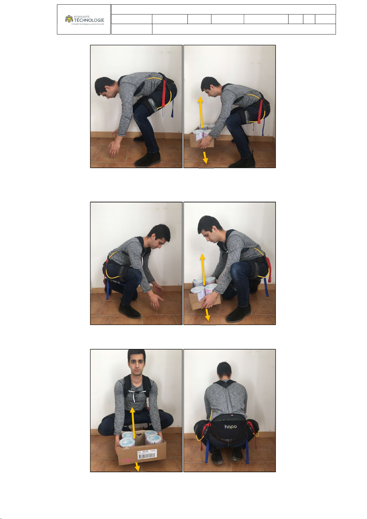
5.5 USE CASES
BENDING OF THE TRUNK:
o Partial flexion (0<back angle<45°); without or with load , static or dynamic.
o Partial flexion (45<back angle<90°); without or with load; static or dynamic.
o Total bending, or hyperbending (>90°); without or with load; static or dynamic.
Figure 7 Figure 8
Figure 9 Figure 10
INSTRUCTIONS
Doc. N°
Rev. 1 Sheet 8 of
36
Title:
o Flexion on one leg (right or left); without or with load; static or dynamic.
CROUCHING (with or without charging port) :
Figure 11 Figure 12
Figure 13 Figure 14
Figure 15 Figure 16
INSTRUCTIONS
Doc. N°
Rev. 1 Sheet 9 of
36
Title:
6. MODE OF OPERATION
6.1 INSTALLATION AND PREPARATION
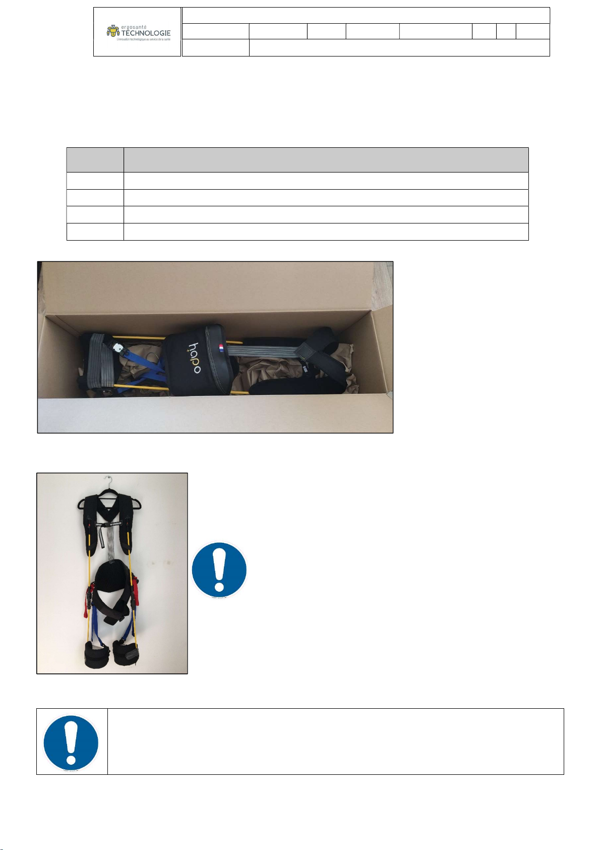
Protect the product from humidity and strong temperature variations.
Open the box, check that the delivery is complete :
Quantity Designation
1 HAPO
1 parts list
1 Hanger
1 User Manual with Certificate of conformity
Recommended disposal of HAPO on hanger :
6.2 USE
The HAPO can be used from a temperature range of -20° to +50°.
Mounting and adjustment steps before fitting :
Tableau 3
Figure 17
Figure 18

INSTRUCTIONS
Doc. N°
Rev. 1 Sheet 10 of
36
Title:
Open all magnetic clips:
o Chest strap :
o Lumbar belt:
o Thigh sleeves :
Figure 19 Figure 20 Figure 21
Figure 22 Figure 23 Figure 24
Figure 25 Figure 26 Figure 27

INSTRUCTIONS
Doc. N°
Rev. 1 Sheet 11 of
36
Title:
Fitting the backpack straps
Step 1: Put on the HAPO from the top by threading the straps from the top like a backpack.
Be careful not to twist the backpack strap:
Step 2 : Clip the chest strap.
Be careful not to twist the strap.
Figure 28 Figure 29 Figure 30
Figure 31
Figure 34
Figure
32
Figure 33

INSTRUCTIONS
Doc. N°
Rev. 1 Sheet 12 of
36
Title:
Step 3 : Adjust the height of the piping (comfort adjustment, so as to spare the throat and chest).
Step 4 : To remove the magnetic clip, pull the tab in the direction indicated.
Figure 35
Figure 36 Figure 37 Figure 38
Figure 39

INSTRUCTIONS
Doc. N°
Rev. 1 Sheet 13 of
36
Title:
Fitting the belt
Step 1 : Position the belt at lumbar level, bring the back of the belt into contact with your back.
Step 2 : Loosen the strap if necessary, disengage the female clip, then clip the fastener.
Figure 40
Figure 41 Figure 42
Figure 43
Figure 44

INSTRUCTIONS
Doc. N°
Rev. 1 Sheet 14 of
36
Title:
Step 3 : Tighten the strap, store the excess in the pouch.
Step 4 : To remove the magnetic clip, loosen the loop, pull the tab in the direction indicated.
Figure 45 Figure 46
Figure 47 Figure 48 Figure 49

INSTRUCTIONS
Doc. N°
Rev. 1 Sheet 15 of
36
Title:
NOTE: IF THE BACKPACK STRAPS ARE PRESSING HARD ON YOUR SHOULDERS, OR IF THEY ARE TOO LOOSE, THE
BACK ELASTIC SHOULD BE ADJUSTED:
Step 1 to adjust the back elastic: Open the pocket in the waistband.
Step 2 to adjust the back elastic: Remove the velcro strap from the back plate.
Step 3 to adjust the back elastic: Reposition it to gain/lose tension.
Figure 50
Figure 51
Figure 52
INSTRUCTIONS
Doc. N°
Rev. 1 Sheet 16 of
36
Title:
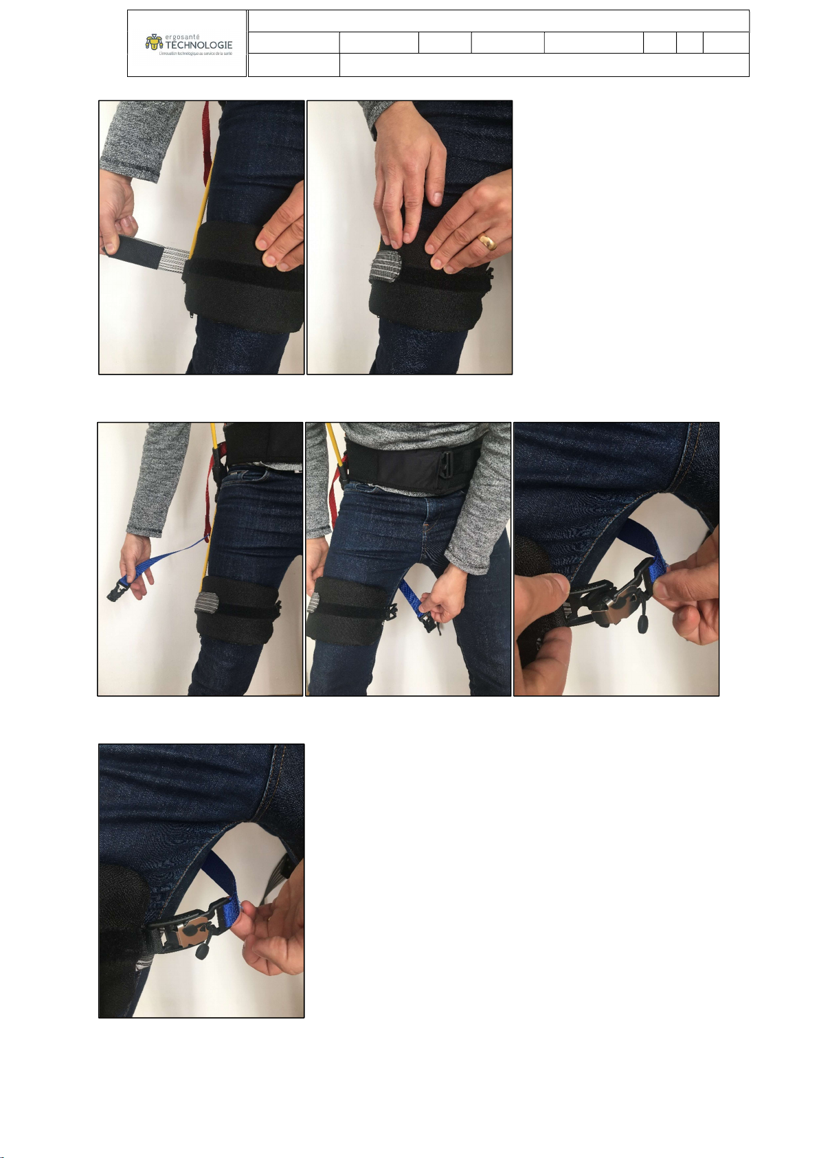
Fitting the sleeves
Check that the springs are unlocked, this will simplify installation:
Step 1 : Position the sleeve on the thigh.
Step 2 : Go around the thigh with the elastic, then attach the elastic with velcro.
Figure 53 Figure 54
Figure 58
Figure 55 Figure 56 Figure 57
INSTRUCTIONS
Doc. N°
Rev. 1 Sheet 17 of
36
Title:
Step 3 : Attach the magnetically-tipped anti-torsion strap to the inside of the sleeve.
Figure 59 Figure 60
Figure 61 Figure 61 Figure 62
Figure 63

INSTRUCTIONS
Doc. N°
Rev. 1 Sheet 18 of
36
Title:
BE CAREFUL NOT TO PASS THE STRAP OVER THE SPRING, RISK OF SPRING BREAKAGE!
Step 4 : Tighten the anti-twist strap (Tighten until there is no slack, without compressing the thigh).
Step 5 : To remove the magnetic clip, pull the tab in the direction indicated.
Figure 64 Figure 65
Figure 66 Figure 67
Figure 68 Figure 69 Figure 70

INSTRUCTIONS
Doc. N°
Rev. 1 Sheet 19 of
36
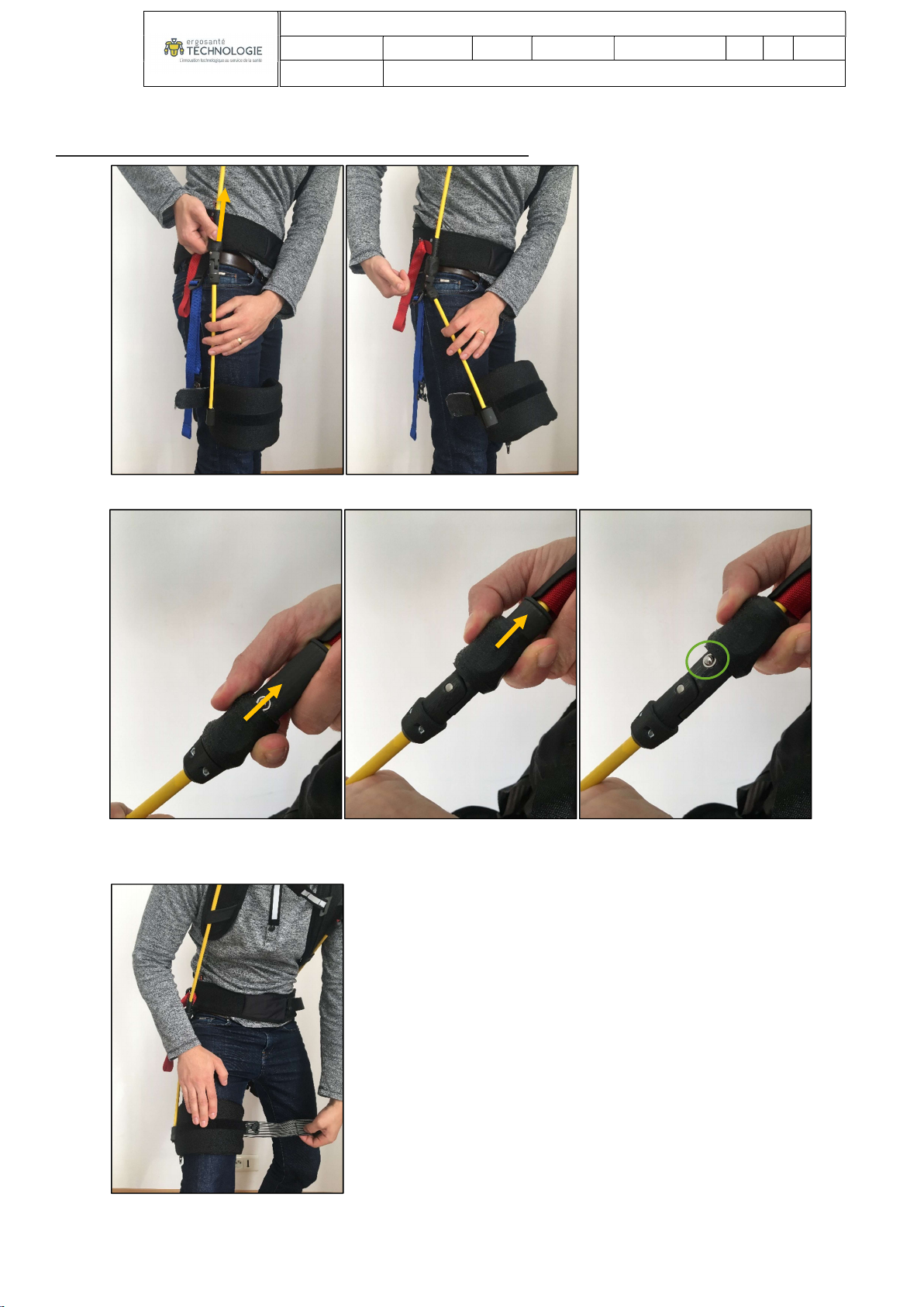
Title:
Locking
Check that the unlocking system is correctly positioned in the straps:
Step 1 : Grasp the shift rail between your thumb and forefinger.
Figure 71 Figure 72
Figure 73 Figure 74 Figure 75

INSTRUCTIONS
Doc. N°
Rev. 1 Sheet 20 of
36
Title:
Step 2 : Push the springs firmly into alignment.
Step 3 : Maintain spring alignment and lower the shift rail completely.
Figure 76 Figure 77
Figure 78 Figure 79
Other manuals for HAPO V1
1
Table of contents
Other Ergosante Technologie Personal Care Product manuals

Popular Personal Care Product manuals by other brands

Electric Mirror
Electric Mirror Sales Demo Kit Assembly and operating instructions

REVLON
REVLON ONE-STEP VOLUMISER PLUS Use and Care Instruction Manual

Coopers of Stortford
Coopers of Stortford vivadia H912 Instructions for use

Panasonic
Panasonic ER417 Service manual

Beper
Beper RI.413 manual

Ricon
Ricon Innovator Service manual

Lindy
Lindy 40165 Instructions for use manual

DURAVIT
DURAVIT Brioso BR 7021 Mounting instructions

Invacare
Invacare 6908 Assembly, installation and operating instructions

natus
natus neoBLUE cozy Service manual

DCG
DCG Belle skin LS2670 instruction manual

GESS
GESS EcoSapiens INFRALIGHT ENILTH/IL/TZ/K-220v quick start guide


