Sunquest Super V6000 VHO User manual

ASSEMBLY AND USER GUIDE
MODEL SUPER V6000 VHO
21742A
®

What Is Covered?
SunQuest warrants your tanning unit to be free of structural defects in its material
and workmanship, under normal use, for its lifetime. SunQuest will repair or
replace, at their discretion, any defect to the structure which affects the
performance of the unit.
For 6 months from the date of purchase, SunQuest will provide replacements for
parts that prove to be defective in material or workmanship. Acrylic shields,
fluorescent lamps, and lamp starters are excluded from this warranty. Labor will be
covered for 30 days from purchase date. Normal wear, damage from misuse or
abuse, damage incurred in transit, or damage done by unauthorized repairs or
modifications are not covered by this warranty.
How to Obtain Service
All warranty service must be performed by an authorized service person. If your
tanning unit must be returned for service, all freight charges must be at your
expense. Contact your place of purchase for the address of the SunQuest Service
Center nearest you. Proof of purchase is required to obtain warranty service.
Other Provisions
This warranty covers the original purchaser only. This warranty is void if the unit is
modified in any manner from its original design.
This warranty gives you specific legal rights, and you may also have other rights
which may vary from state to state.
ifetime Warranty
L
i

Congratulations on your purchase of this technologically advanced sun
tanning unit. It has been designed to provide years of dependable service
for you.
Please read all the instructions in this booklet before installing and using
the unit. Always be sure to observe all safety precautions.
ontents
Safety Information . . . . . . . . . . . . . . . . . . . . . . . . . . . . . . . . . . . . . .iii
Installation . . . . . . . . . . . . . . . . . . . . . . . . . . . . . . . . . . . . . . . . . . . .1
Tools Required . . . . . . . . . . . . . . . . . . . . . . . . . . . . . . . . . . . . .1
Pre-Installation Planning . . . . . . . . . . . . . . . . . . . . . . . . . . . . . .1
Assembly . . . . . . . . . . . . . . . . . . . . . . . . . . . . . . . . . . . . . . . . .2
Bypass Plug . . . . . . . . . . . . . . . . . . . . . . . . . . . . . . . . . . . . . . .4
Remote Connections . . . . . . . . . . . . . . . . . . . . . . . . . . . . . . . .5
Operation . . . . . . . . . . . . . . . . . . . . . . . . . . . . . . . . . . . . . . . . . . . . .7
Before You Tan . . . . . . . . . . . . . . . . . . . . . . . . . . . . . . . . . . . .7
Exposure Times . . . . . . . . . . . . . . . . . . . . . . . . . . . . . . . . . . . .7
Using Your Booth . . . . . . . . . . . . . . . . . . . . . . . . . . . . . . . . . . .8
Care and Maintenance . . . . . . . . . . . . . . . . . . . . . . . . . . . . . . . . . .10
Cleaning After Use . . . . . . . . . . . . . . . . . . . . . . . . . . . . . . . . .10
Thorough Periodic Cleaning . . . . . . . . . . . . . . . . . . . . . . . . . .10
Mechanical Inspection . . . . . . . . . . . . . . . . . . . . . . . . . . . . . .10
Replacing Lamps . . . . . . . . . . . . . . . . . . . . . . . . . . . . . . . . . .11
Troubleshooting . . . . . . . . . . . . . . . . . . . . . . . . . . . . . . . . . . . . . . .12
Obtaining Service . . . . . . . . . . . . . . . . . . . . . . . . . . . . . . . . . . . . . .15
elcome
W
ii

iii
afety Information
s
LABELING NOTICE: Labels are affixed on all systems to inform the user of possible dangers. Regulations are stated in
21 CFR, Section 10 0.20, and require that all products manufactured after September 8, 1986 which use sunlamps
must display the following:
Ultraviolet radiation. Follow instructions. Avoid overexposure. As with natural sunlight, over-expo-
sure can cause eye and skin injury and allergic reactions. Repeated exposure may cause pre-
mature aging of the skin and skin cancer. WEAR PROTECTIVE EYEWEAR; FAILURE TO MAY RESULT IN SEVERE BURNS
OR LONGTERM INJURY TO THE EYES.
Medications or cosmetics may increase your sensitivity to the ultraviolet radiation. Consult physician before using
sunlamp if you are using medications or have a history of skin problems or believe yourself especially sensitive to
sunlight. If you do not tan in the sun, you are unlikely to tan from the use of this product.
Do not use without clear plastic panels (or wire grid for models using wire grid) in place. Tanning normally appears
after the first few sessions and maximizes after approximately four weeks. Tan once or twice per week thereafter to
maintain appearance. Frequency of sessions should be limited to every other day. Persons already having a base
tan may begin at advanced levels corresponding to the extent of their base tan.
New lamps emit approximately 20% more UV during the first 50 hours of operation. Recommended tanning times
should therefore be reduced by approximately 20% during that period.
For a uniform tan, center yourself within the booth both front and back and to the left and right. This will result in
your body being equidistant from all lamps. Other positions may result in over exposure to parts of your body.
Use only the lamp listed below or certified equivalents, as failure to will result in non-compliance with federal regu-
lations.
Accelerator®Wolff®Model ACC75-T12-160W B P n
Provided eyeshields (Lucas Products Super Sunnies or Intrexco No. 5635/1) or equivalent eyewear as defined under
21 CFR 10 0.20. Other types of eyewear may not provide adequate protection. Disconnect power before
attempting to clean, relamp, or engage in the maintenance of this product.
THIS EQUIPMENT MUST BE CONNECTED TO EARTH GROUND.
THIS PRODUCT IS IN CONFORMITY WITH PERFORMANCE STANDARDS FOR SUN LAMP PRODUCTS UNDER 21 CFR
PART 10 0.20
DANGER
RECOMMENDED EXPOSURE TIMES IN MINUTES MAXIMUM EXPOSURE TIME IS 10 MINUTES
Sk n Type: Week # Week 1 Week 2 Week 3 Week 4 Subsequent
Sess on # 1st-3rd 4th-6th 7th-10th 11th-13th Max mum
I Sens t ve Sk n (Burns eas ly and severely and does not tan.) NOT RECOMMENDED FOR TANNING
II L ght (Burns eas ly and severely and tans m n mally.)
III Normal (Burns moderately and tans average.)
IV Dark (Burns m n mally, tans eas ly and above average.)
2
3
4
4
5
6
6
7
8
8
10
10
10
10
10

nstallation
I
1
Tools Required
You’ll need the following tools to assemble your booth:
Knife (Utility or similar)#2 Phillips Screw Driver Adjustable Wrench
Pre-Installation Planning
Before you begin to assemble your booth, you should observe the following pre-
installation considerations.
• Your booth operates from a 220V AC source. The unit must be hard-
wired to a dedicated circuit capable of providing 60 amp service.
Electrical connection of this unit requires a professional electrician.
• IMPORTANT! Voltage must be below 230 VAC or may require a Buck
Booster, contact ETS service at the number at the back of this guide. Use
of a voltage source above 230 VAC may reduce the life of some compo-
nents in your booth.
• Make sure the room in which you intend to use your booth is well ven-
tilated. Air from the room is used to cool the booth, and a poorly venti-
lated room may cause the unit to become hot and cause discomfort to
the user.
• Your sunbed is designed to operate in an ambient room temperature of
80°F maximum and 70% relative humidity.

• The SunQuest Super V6000 VHO must be installed in a room with a
minimum ceiling height of eight (8) feet. Place your booth no closer than
6" from any wall.
• Proper assembly of your booth requires three people. Plan to have a
couple of helpers assist you.
• Record the serial number of the booth in the area provided on the
back page of this manual. This information will be required whenever you
call customer service.
2
Installation-Pre-Installation Planning
Assembly
1. Each of the unit’s halves should be placed together at the desired installation loca-
tion. Align the holes (A), located at the top and bottom of the unit.Remove the ship-
ping bars which are located at the top of the unit connecting the door to the back of
the unit.
Caution: Once the shipping bars are removed, the halves can easily fall over.
Minimize this risk by keeping the door panels in the same positions as they were
before removing the shipping bars and then immediately connect the halves.
With the holes aligned, secure the two halves of the unit to one another using the
four (5/16x3/4 Hex Head) bolts. Secure them using the nuts provided. Do not tighten
them at this time.
A
Back of unit
B

2. Lower all six of the leveling posts (C) until the weight is almost completely
removed from the casters (D). Check the front doors to see if the tops of the doors
are level with each other when closed, it may be necessary to further adjust the lev-
elers. After the unit is level tighten the nuts left loose from Step 1.
HINT: If you are having difficulty in leveling the booth remember that extending the
right rear leveler will have an opposite effect, i.e., it will tend to lower the right front
of the unit. If necessary adjust the casters under the doors. The door casters should
bear only the weight of the doors. When properly adjusted the doors will open and
close easily. There should be no gap between the doors when closed.
Installation-Assembly
3
C
3. Connect the electrical connectors at the rear top of the unit. Slide the black split
grommet found in the accessory kit around the wire assembly and then press the
grommet into slot (B). Now mount the white metal cap cover over the connection,
by using two #10x1/4 Phillips screws. Be careful not to crimp, bind or pinch any of
the wires.
4. Attach the exterior handles to the doors using the pre-installed screws (E).
D
E

Bypass Plug
Connect the remote control bypass plug (G) to the remote control port (H). The
bypass plug can be inserted into either port. Your booth will not operate without the
bypass plug or a remote system connected. If you plan on using a remote system
refer to “Remote Connections”.
Note: The remote control device is optional and is not included with your booth.
Caution: Remove the bypass plug when using a remote system, except for the case
when the booth is at the end of a ComputaTAN™ or T-Max®Manager series.
Installation- Electrical Connections
4
5. Place the platform inside of the unit oriented so that the side without the air reg-
ister is toward the front. Connect the plug from the plateform to the connection
located underneath the corner of the booth (F).
F
6. Prepare to mount the control console to the top rear of the booth. You will
notice the four mounting holes and the two attaching wire harnesses. Connect the
multi-pin connector from the booth to the mating connector on the console. Mount
the console to the booth using four #10X1/4 Phillips screws. Attach the single
ground wire with one of these screws.
G
H

Remote Connections
Your booth incorporates advanced circuitry allowing it to connect and communicate with
most remote control systems. If a remote system is to be used, the type of system you are
using must first be determined.
Warning: The remote connection is not designed to supply or accept high voltage,
nor can it provide power to an external timer. Only use remote systems that incorporate an
isolated contact or relay, or the ComputaTAN™or T-Max®remote systems. Failure to do so
will void your warranty and may damage the booth.
Caution: Remove the bypass plug when using a remote system except for the
case when the booth is at the end of a ComputaTAN™or T-Max®Manager series.
ComputaTAN™ or T-Max®Manager Remote Systems
The ComputaTAN™and T-Max®Manager remote systems offer the ultimate in booth con-
trol, while allowing the tanner easy straightforward operation. Your booth is already config-
ured to directly connect to these systems. To connect your booth to either of this systems
follow the instructions that came with your remote system, noting the hints listed below. If
you still have questions call ETS at the phone number listed at the back of this guide.
Setting the address Before connecting your booth to either the ComputaTAN™or
T-Max®Manager series, the address or “id” of your booth must first be set. Each
booth connected to the series must have a different “id” number . To set the
address,
1. Verify that the booth display is indicating a “0”.
2. Press and hold the stop button located on the booth display for three sec
onds and release. The display should indicate an “id” number from 1 to 99.
3. Set the “id” to a unique number by pressing the timer button until the desired
number is achieved. Holding in the timer button will increase the “id” scroll rate.
4. Press the stop button to return to the normal display mode.
Note: If you are having trouble getting into the “id” mode, it is probably because
you have already attempted to connect your booth to the remote system.
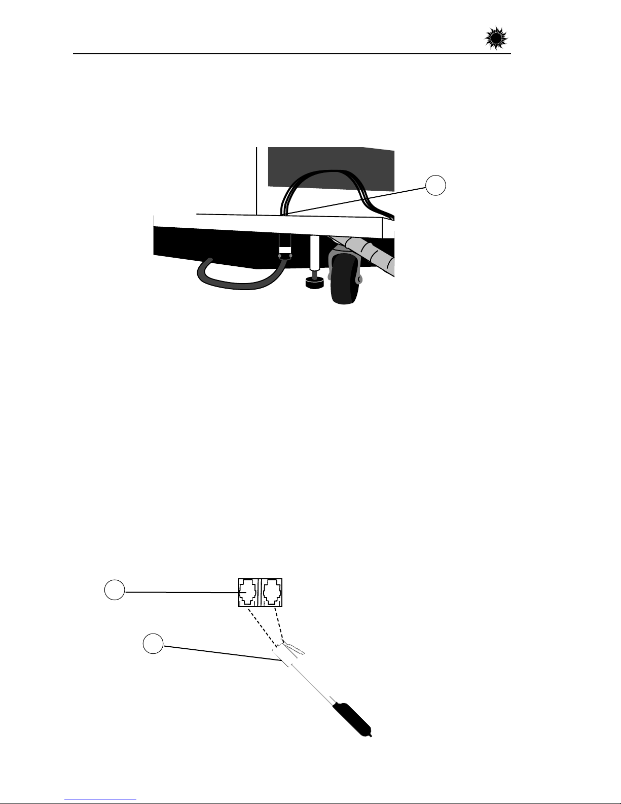
Disconnect the remote plug(s) from the ports located on the top right hand corner
of the rear of the booth, wait 90 seconds and try again.
T-Max®Manager The T-Max®1A is not needed when connecting your booth to
the T-Max®Manager series. The circuitry inside your booth eliminates the need for
the T-Max®1A. Simply connect the RJ-22 Modular cable(s) described in the T-
Max®Manager manual directly into the port(s) located on the top right hand cor
ner of the rear of the booth You can place your booth at any location in the series.
Remember the last connection in the series requires a terminator plug.
5
Installation–Remote Connections

6
Note: The by-pass plug provided with your booth will work wherever a T-Max®terminator is
called for in the series. The terminator provided by T-Max®will not work as an bypass plug.
Remote systems using a Control Relay
Most modern remote systems control the booth by the use of a relay. The relay operates the
booth by connecting and disconnecting a pair of wires leading from the booth. Refer to the
user’s manual provided with your remote system to determine if it operates in this way. To
connect your booth to this type of system a remote interface kit is required. Call ETS at the
phone number listed at the back of this guide to obtain the kit. Follow the instructions pro-
vided with the kit and from the remote’s manual to make the necessary connections.
Caution: Remove the bypass plug when using this type of remote system.
Installation–Remote Connections

7
Before You Tan
Before using your booth, please note the following important precautions:
• WARNING your booth is designed for individual use. Only one pair
of protective goggles is provided. Always wear these or another approved
pair of goggles. Regular sunglasses do not provide adequate protection
from ultraviolet light. You should never look at the lamps when turned
on without wearing the appropriate protective goggles.
• Some medication may increase your sensitivity to ultraviolet light. It is
recommended that you consult a physician before using this booth if
taking any medication or if you suspect that your skin might be especially
sensitive to sunlight. Included with this manual is an FDA booklet on
medications that increase sensitivity to light.
• As with all electrical appliances, do not operate this device near water
or while you are wet.
Exposure Times
We recommend that you tan every other day, following the tanning times in the
exposure schedule. Tanning normally appears after the first few sessions and maxi-
mizes after approximately four weeks. Tan once or twice per week thereafter to
maintain appearance. Persons already having a base tan may begin at advanced
levels corresponding to the extent of their base tan.
Follow the guidelines for skin type and exposure times as shown in the table below.
peration
O
RECOMMENDED EXPOSURE TIMES IN MINUTES MAXIMUM EXPOSURE TIME IS 10 MINUTES
Sk n Type: Week # Week 1 Week 2 Week 3 Week 4 Subsequent
Sess on # 1st-3rd 4th-6th 7th-10th 11th-13th Max mum
I Sens t ve Sk n (Burns eas ly and severely and does not tan.) NOT RECOMMENDED FOR TANNING
II L ght (Burns eas ly and severely and tans m n mally.)
III Normal (Burns moderately and tans average.)
IV Dark (Burns m n mally, tans eas ly and above average.)
2
3
4
4
5
6
6
7
8
8
10
10
10
10
10

Using Your Booth
When configured as a stand alone unit or when connected to a remote system using a
control relay.
If your booth is connected to a ComputaTAN™ or T-Max®Manager remote system, turn
to Using Your Booth When connected to the ComputaTAN™or T-Max®Manager.
Step 1. Enter the booth and shut the door behind you. Center your body on the pedestal
so that it will allow for even tanning.
Step 2. Start the booth by pressing the timer button (E) located on the control console
located at the top of the booth. The lamps will turn on and the timer display (C) will indi-
cate the session time remaining.
Note: If the lamps do not come on then either the remote bypass plug is not installed see,
Making Electrical Connections or an external timer is being used that has not yet been acti-
vated. The timer will not begin to count down until the remote system activates.
Step 3. If less than the maximum tanning time is desired, repeatedly press the timer button
(E) until the desired time is indicated.
Step 4. Turn on the body fans located in the pedestal by pressing button (A). View indicator
(B) to determine the if body fans are on. When the bar (B) is fully lit the fans are on and
when nothing is lit they are off.
Step 5. When the timer reaches 0, the lamps will turn off. If you want to stop your session
before the time expires press the stop button (D). The booth will then allow you ten sec-
onds to reactivate the unit with the unused time. After ten seconds the timer system resets
back to 0 minutes.
Step 6. Exit the booth when the lamps shut off. The cooling fans run for 3 minutes after the
lamps shut off to aid in cooling the booth.
A B C D E
8
Operation-Using Your Booth

Using Your Booth
When connected to the ComputaTAN™ or T-Max®Manager
Step 1. Enter the booth and shut the door behind you. Center your body on the pedestal so
that it will allow for even tanning.
Step 2. Observe the timer display. Assuming the remote system has been set to allow a pre-
tanning delay time, the display will repeatedly flash the delay symbol “dL” and then the
remaining delay time. Either press the timer button (E) or wait until the delay time has expired
to begin the tanning session. The display will now indicate the tanning time set by the
remote system, the lamps will turn on and the timer will begin to count down. The booth will
not allow a session time greater than the booth’s maximum exposure time.
If the timer did not display a “dL” but does indicate a;
“0” then the remote device has not yet been set.
tanning time and the lamps have come on, then either a delay time was not set or
the delay time has already expired and the tanning session has begun.
tanning time and the lamps have not come on, then the auto start function of the
external remote system has been turned off. Press the timer button(E) to turn on the
lamps.
Step 3. If a tanning time less than the displayed time is desired repeatedly press the timer
button(E) to decrease the remaining time.
Step 4. To turn on or off the the fans, located in the pedestal press button (A). When the bar
(B) is fully lit the fans are on and when nothing is lit they are off.
Step 5. When the timer goes below 1 minute it will begin to count in seconds until it reaches
0, then the lamps turn off. If you want to stop your session before time expires press the stop
button (D).
Operation-Using Your Booth
9
A B C D E

Cleaning After Use
Clean and disinfect your tanning booth’s pedestal, handles, control console and wire grid
after each use. Use a non-abrasive disinfectant cleaner. We recommend SunQuest disin-
fectant. Spray a clean soft cloth with disinfectant and then clean all surfaces that the tan-
ner may have come in contact with.
Thorough Periodic Cleaning
Introduction
The cooling fans draw air through the booth and over time will cause a dust buildup on
the lamps and reflectors. This will reduce the tanning effectiveness of the booth. When a
dust buildup is observed, it is necessary to thoroughly clean the inside of the booth.
Warning! Disconnect booth from electrical power before cleaning.
Cleaning the Booth
Step 1. Remove the wire grids and lamps as described in Replacing Lamps.
Step 2. With a soft cloth, wipe the entire length of each lamp and reflector
to remove any film build-up.
Step 3. Re-install the lamps and wire grids as described in Replacing Lamps.
Mechanical Inspection
Your tanning booth has been built for years of service. To ensure trouble free operation
throughout its life, inspect the unit’s mechanical integrity every 400-500 hours of use.
• Inspect the unit’s fasteners verifying that all are firmly in place. Pay particular attention
to the door alignment. Adjust the door casters as needed. See Assembly Step 2.
• Inspect the AC power cable and its connections.
10
are & Maintenance

Removing/Replacing Lamps
After removing the grids, replace lamps as follows:
Step 1. Grasp the lamp at one end and at the middle, then turn the
lamp a quarter turn. The lamp may then be gently removed
from its holder.
Step 2. To re-install a lamp, insert the pins located on the ends of the
lamp into the slots on top of the lamp holder and turn the
lamp a quarter turn.
Recommended Replacement Lamps
We recommend using the lamps specified below. Use of uncertified lamps is a viola-
tion of federal regulations and will void your warranty. These lamps have an average
life of 800-1000 hours of effective tanning use. Lamps used longer than that begin
to lose their effectiveness even though they will continue to light.
Only the following lamp type has been certified for use in your SunQuest booth:
Accelerator®Wolff®Model ACC75-T12-160W Bi Pin
11
Care & Maintenance-Replacing Lamps
Replacing Lamps
Introduction
Your tanning booth has an hour meter which keeps track of how many hours the
booth has been in operation. Use this meter to determine when your tanning lamps
should be replaced. To be assured of maximum tanning effectiveness, change lamps
after approximately 800-1000 hours of use. Tanning will continue after this time but
at a slower rate. To ensure trouble-free operation of your sunbed, replace the lamp
starters whenever the lamps are replaced.
Warning! Disconnect the booth from electrical power before servicing.
Removing/Replacing Wire Grids
The wire grids in the booth are secured in place by screws, remove these screws
located at the top and bottom of the grid to remove the grid.
After changing lamps, replace the grids and screws.

SolutionProblem
1. Make sure the unit is connect to a power source.
2. Check source of ac power. Reset circuit breaker or
replace fuse.
1.ComputaTAN™ or T-Max®Manager remote system has
not yet been set.
1.Bypass plug is not installed see making electrical con-
nections.
2.If remote is being used other than ComputaTAN™ or T-
Max®Manager, remote wiring is incorrect, see the
instructions provided with the remote interface kit.
The auto start feature of the remote system is disabled,
see the instructions provided with your remote system.
1.The booth must first be set to a unique address see
remote connections.
2.The bypass or terminator plug may be installed in the
series in an inappropriate location. Plug the bypass plug
only into the booth at the end of the series.
Lamps fail to light and timer
display is blank
Timer display continues to
show a 0 after the timer button
is pressed
Timer display changes to indi-
cate a tanning time after the
timer button is pressed but
lamps do not come on
My booth is connected to the
ComputaTan™ or T-Max ®
Manager remote system and
when the delay time has
expired the timer display starts
counting down but the booth
lights do not come on
My booth won’t work with the
ComputaTan™ or T-max ®
Manager remote systems
12
roubleshooting
T
Problem/Solution Chart

SolutionProblem
13
1.Check that lamp is installed correctly.
2.Switch unlit lamp with a lamp that lights, if the new
lamp lights and the old lamps still does not, replace old
lamp.
Body lamps are on when they should be off, have serv-
ice technician check the contactor.
Body lamps are off when they should be on, have ser-
vicer check contactor and its wiring from the main timer
box .
Body lamps are on when they should be off, have serv-
ice technician check the contactor.
Body lamps are off when they should be on, have serv-
ice technician check the contactor and its wiring from the
main timer box.
Not currently used
Not currently used
One or more lamps fail to light
Timer display is indicating Er 1
Timer display is indicating Er 2
Timer display is indicating Er 3
Timer display is indicating Er 4
Timer display is indicating Er 5
Timer display is indicating Er 6
Problem/Solution Chart
Troubleshooting-Problems/Solution Chart

SolutionProblem
14
Face Tanner contactor is closed when it should be open,
have service technician check the contactor.
Face Tanner contactor is open when it should be closed,
have service technician check the contactor and its wiring
from the main timer box.
Ballast Drawer is open or drawer switch is broken.
Timer computer is in an illegal state, reset power to cor-
rect, replace main timer if error reoccurs.
Timer configuration is corrupt, replace timer.
Timer computer is in an illegal state, reset power to cor-
rect, replace main timer if error reoccurs.
The timer display is not responding;
1. Check cable to display.
2. Replace display assembly.
3. Replace main timer box.
Timer configuration is corrupt, replace timer.
Timer display is indicating Er 7
Timer display is indicating Er 8
Timer display is indicating Er 9
Timer display is indicating Er 10
Timer display is indicating Er 11
Timer display is indicating Er 12
Timer display is indicating Er 13
Timer display is indicating Er 14
Timer display is indicating Er 15
Problem/Solution Chart
Troubleshooting-Problems/Solution Chart

15
btaining Service
O
To arrange for service, or for more information about your sunbed,
contact ETS as follows:
CALL FOR SERVICE OR QUESTIONS:
1•800•449•3605
6270 Corporate Drive
Indianapolis, IN 46278-2900
Have the following information ready when calling ETS
to order parts or service for your bed:
Manufactured for SunQuest by:
Spectrum Products, Inc.
6220 Churchman Bypass
Indianapolis, Indiana 46203
Date Purchased
Booth Serial Number

Table of contents
Other Sunquest Personal Care Product manuals