2.2 Performance Verification
This section discusses the tests necessary to verify UUT performance.
Verifying General Performance (Section 2.2.1)
Adjusting the Light Intensity (Section 2.2.2)
All tests can be conducted without removing the UUT light enclosure. If the UUT fails to conform
or cannot be adjusted to conform, repairs must be made to correct the problem before the
instrument is returned to the user.
Tools and Test Equipment Type
Radiometer* Natus neoBLUE® Radiometer (P/N 53870) or equivalent*
Potentiometer Adjustment Tool GC Electronics 8608 or equivalent
Safety Glasses
Guard Dog Bones glasses (p/n 413BB) are recommended
and are available online at www.safetyglasses.com or via
phone at 1-800-870-6189.
Thermometer Use a model appropriate for measuring surface
temperature
Work Pad Any non-abrasive non-static surface
Note: *If a different radiometer is used, please refer to the Conversion Chart in Appendix A.
If the meter is not listed, please contact Natus Technical Service before adjusting light
intensity. Use of a radiometer with a HOLD feature is necessary if the radiometer display
cannot be read while the radiometer sensor is faced down.
Intensity measurements are based on the patient surface using Natus air mattress and
disposable mattress cover. Use of other components may produce unexpected levels of light
intensity.
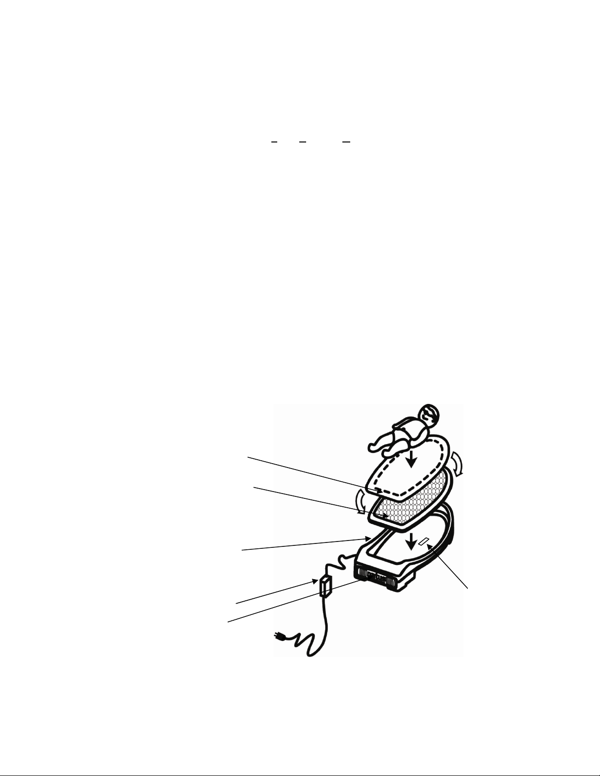
2.2.1 Verifying General Performance
1. Confirm air vents are not blocked.
2. Connect the power supply DC power cord to the UUT DC input and the power supply AC
cord to a medical grade AC receptacle or an appropriately grounded receptacle.
Warning! Operator Safety - Bright light source: Do not look directly at LED
components from above. Sensitive individuals may experience
headache, nausea, or mild vertigo when exposed to the illuminated
area.
Observe from an angle of 15° or greater. To alleviate potential effects,
use the UUT in a well-lit area or wear yellow or tinted safety glasses.
3. Switch the UUT on. Verify the ventilation fan is running and the LED panel lights.
4. Remove the mattress and mattress cover from the enclosure.
5. Examine light panel geometry for unlit LED components.
neoBLUE® cozy Service Manual 6 P/N 051915 Rev. D