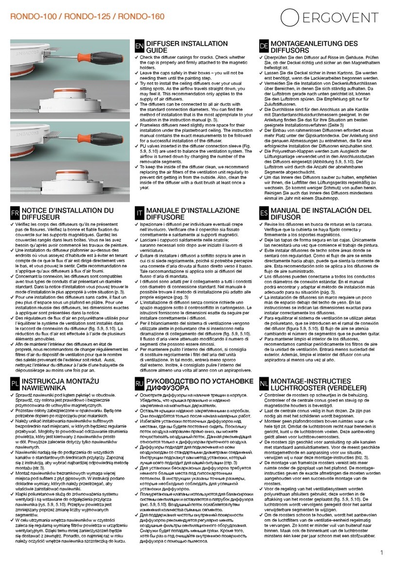
ergovent KVADRO-100 User manual

Diuser preparation
Installation Method No. 1
(connected via a exible corrugated pipe)
Installation Method No. 2
(connection via a standard plenum box when the
ceiling panels have not yet been attached)
Integrated diuser nishing
Diuser maintenance
......................................................... page 7
............................................. page 8
............................................ page 9
...................................... page 11
................................................... page 12
Remove the diusers and side brackets from the boxes. Inspect
each diuser for any cracks in the housing. Leave the covers
securely in the boxes (Image 1), as they will only be needed when
starting the painting.
7
KVADRO-100 / KVADRO-125
Use screws to attach the side fasteners. They can be applied to 1
or 2 layers of plasterboard.
1 layer: the element is placed against the edge (Image 2);
2 layers: the fastening is aligned with the protruding brim in the
housing (Image 3).
INSTALLATION METHOD No. 1 (page 8)
METAL DUCT SYSTEM
Connection: via a exible corrugated pipe.
INSTALLATION METHOD No. 2 (page 9)
75 mm PLASTIC DUCT SYSTEM
Connection: via a plenum box (metal/plastic).
Ceiling plasterboards are not yet attached.
DIFFUSER PREPARATION SELECTION OF THE INSTALLATION METHOD
DIFFUSER INSTALLATION GUIDE
EN
Three installation methods are possible. You
will recognise which method is suitable for you
by looking at the images depicting dierent
situations. Choose the installation method
that best suits your situation and follow the
appropriate instructions.
•
1
2
3
www.ergovent.com

Cut a hole for the diuser in the intended place (Image 1.1).
Tilt the diuser at an angle and insert it through the hole (Image
1.4). Then place it in the intended position (the side fastenings
must rest on the plasterboard).
Connection via a exible corrugated pipe
When planning the diuser installation points, make sure that
there are no ceiling frame proles in the diuser installation area.
Any proles present in the area of the cut-out hole and creating
an obstruction must be removed (Image 1.2). Be sure to consult
with the ceiling installers to ensure that you will not damage the
ceiling structure.
Check that the diuser installation is level. The diuser must
be ush with the ceiling surface or can protrude by up to 1 mm
(Image 1.5).
Attach the exible corrugated pipe to the diuser connector. A
clamp or plastic strap will suce (Image 1.3).
The diuser is fastened with self-tapping screws. Insert the
screws directly through the plasterboard into the side fasteners
(Image 1.6).
INSTALLATION METHOD NO. 1
1.3
1.2
1.4
1.5
1.6
When connecting the diusers via a exible
corrugated pipe, the gypsum ceiling panels
must be already attached.
If the diuser is awry, the side brackets have
been attached at dierent levels. Remove the
diuser and readjust the fasteners.
The diuser is ready for nishing.
Go to the nishing instructions (page 11).
8
•
•
0-1mm
Gypsum ceiling
diuser
EN
www.ergovent.com
A
A
1.1
A=242 mm

Connection via a plenum box (75 mm plastic duct system)
• If the plenum box is plastic, a successful installation will require
at least 7 cm of space from the duct to the bottom of the ceiling
prole (Image 2.5). If two layers of plasterboard will be used, the
distance required is 6 cm (Figure 2.6).
min 7,5cm
INSTALLATION METHOD NO. 2
2.1 2.2
Make sure that the gypsum ceiling structure does not interfere
with the installation of the diusers (Image 2.1).
Metal ceiling proles should be at least 7,5 cm away from the
connection pipe (Image 2.2).
Make sure there is enough space for a successful
diuser installation:
• If the plenum box is metal, a successful installation will require
at least 7 cm of space from the box housing to the bottom of
the ceiling prole (Image 2.3). If two layers of plasterboard will be
used, the distance required is 6 cm (Figure 2.4).
SHORTENING THE CONNECTION PIPES
The connecting pipes must be shortened by measuring Distance
A from the level of the lower prole surface (Images 2.7 and 2.8).
min 7cm
min 6cm
min 7cm
A
For 1 layer of plasterboard, A = 4,5 cm
For 2 layers of plasterboard, A = 3,5 cm
min 6cm
9
2.3
2.4
2.5
2.6
2.7
2.8
EN
www.ergovent.com

The diuser coupling is then inserted into the connection pipe
(Image 2.9). Continue moving the coupling inwards until it touches
the pipe (Figure 2.10).
Check that the diuser is level with respect to the visible
ceiling surface (Image 2.13). The visible edge of the diuser
must be ush with the ceiling or can protrude by up to 1 mm.
If the diuser is awry, the side brackets have been attached at
dierent levels. In this case, remove the diuser and readjust the
fasteners.
For 2 layers of plasterboard:
After attaching the rst layer of plaster, the diuser housing
should protrude by about 13 mm (Image 2.14). After attaching the
second layer, the housing must be ush with the plasterboard or
protruding by up to 1 mm.
After inserting the diuser, make sure that it is being held
securely and will not fall out while you prepare the ceiling panel. If
necessary, use mounting tape for a temporary fastening to prevent
the diuser from falling out (Image 2.11).
For 1 layer of plasterboard:
Cut out a hole in the required place and attach the board using
screws (Image 2.12).
The diuser is fastened with self-tapping screws (Image 2.15).
Insert the screws directly through the plasterboard into the side
fasteners.
The diuser is ready for nishing.
Go to the nishing instructions (page 11).
0-1mm
13mm
Gypsum ceiling
Gypsum ceiling
diuser
diuser
INSERTING THE DIFFUSER
ATTACHMENT OF THE PLASTERBOARD
DIFFUSER ATTACHMENT
10
Insert the diuser just before preparing to
attach the ceiling plasterboards.
•
2.9
2.11
2.12
2.10 2.13
2.14
2.15
EN
www.ergovent.com
A
A
A=242 mm

Rendering / reinforcement / painting
Fill the gap between the diuser and the plasterboard with putty.
We recommend using Knauf Fugenfuler or Uniott putty (Image
3.1).
Apply another coat of putty (Image 3.4). Once the putty has
hardened, rub it with a ne sandpaper.
When the putty has dried, cut out the breglass cloth in the central
part of the diuser. Use a sharp knife to cut it ush with the inner
edge of the diuser, while making sure not to damage the gypsum
housing (Image 3.3).
Cut out 35 x 35 cm sheets from a thin breglass cloth. Press the
breglass cloth into the putty, directly over the diuser area. When
pressing the cloth into the putty, smooth it out to ensure an even
covering with the layer of putty (Image 3.2).
The centre cover does not need to be plastered prior to painting,
as priming it will suce. Paint only the visible surfaces of the
centre cover (Image 3.6).
The entire inner surface of the diuser must be painted with the
ceiling paint (Image 3.5).
FINISHING INSTRUCTIONS
Prior to painting, impregnate the rendered
surfaces with a deep primer; use a moisture-
resistant primer for damp rooms.
In damp rooms, use moisture-resistant ceiling
paints that are specially designated for these
types of rooms.
•
•
RENDERING AND REINFORCEMENT
PAINTING
11
3.1
3.2 3.5
3.4
3.3
We recommend using the Knauf nishing
technology for your nishing work.
Remove dust from surfaces and gaps. Use
Ceresit CT-17 or Knauf Tiefgrund primers.
To avoid cracks in the seam, we recommend
reinforcing the entire seam area with breglass
cloth.
•
•
•
EN
www.ergovent.com

When the paint is completely dry, the cover can be put in place.
The cover is attached to three magnetic holders (Image 3.7).
Adjust the magnetic holders so that each holder protrudes by 15
mm from the diuser housing (Image 3.8).
The diuser installation is now complete (Image 3.9).
Valve installation. Remove the diuser cover. Insert the exible
valve into the diuser connection branch. The air ow is regulated
by changing the number of valve segments (Image 3.10).
We recommend cleaning the diuser at least once a year. Use
a soft duster to clean the inside of the diuser, to prevent dirt
from accumulating and sticking to the device if it is left unclean for
prolonged periods of time. Accumulated dust can also be removed
with a vacuum cleaner. Avoid damaging the painted surface.
AIR FLOW REGULATION
DIFFUSER MAINTENANCE
The diuser cover must always be ush with
the ceiling.
If is it necessary to regulate the air ow, we
recommend the additional purchase and use
of an INNO valve. These come in standard
diameters of 100 mm, 125 mm or 160 mm.
To maintain a clean device, change the
actuator lters inside the air diuser regularly.
This will reduce the penetration of impurities
from outside and keep the diuser clean for
longer.
•
•
•
12
3.6
3.7 3.10
3.8
3.9 3.11
15mm
EN
www.ergovent.com
This manual suits for next models
1
Table of contents
Other ergovent Fan manuals
Popular Fan manuals by other brands

El Corte Inglés
El Corte Inglés VT-90 instruction manual
Hunter
Hunter Builder Deluxe 53089 Owner's guide and installation manual
pottorff
pottorff BD Series installation instructions

MTD
MTD MTD-ERV 350 Installation & operating manual

BLAUBERG Ventilatoren
BLAUBERG Ventilatoren Iso-Mix user manual

Craftmade
Craftmade Stonegate STO52 installation guide

