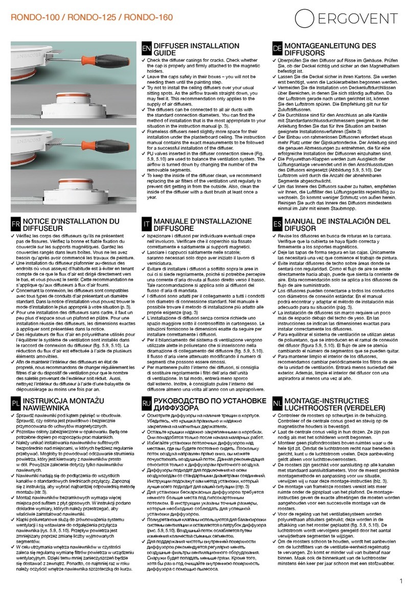
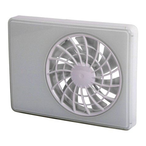
ergovent RONDO-100 User manual

Diuser and plenum box preparation
Installation and duct connection
Attachment of plasterboards
Integrated diuser nishing
Diuser maintenance
.................... page 1
............................. page 1
..................................... page 3
........................................ page 4
...................................................... page 5
Remove the diusers and side brackets from the boxes. Inspect
each diuser for any cracks in the housing. Leave the covers
securely in the boxes (Image 1), as they will only be needed when
starting the painting.
The plenum box is attached to the diuser using three screws in
place of the diuser coupling. The diuser fasteners must face
sideways (Images 4 and 5).
1
Use screws to attach the side fasteners. They can be applied to 1
or 2 layers of plasterboard.
1 layer: the element is placed against the edge (Image 2);
2 layers: the fastening is aligned with the protruding brim in the
housing (Image 3).
DIFFUSER PREPARATION PLENUM BOX ATTACHMENT
EN
1 4
5
2
3
www.ergovent.com
RONDO-100/ RONDO-125
(CONNECTED VIA A LOW PROFILE PLENUM BOX)
DIFFUSER INSTALLATION GUIDE

Mark and drill holes for attaching the box to the concrete ceiling.
Loosen the bolts slightly to allow them to move easily. Insert the
bronze bushings into the holes drilled in the ceiling and tighten the
fastening bolts (Image 6).
Fasten the upper ceiling B proles parallel to the ducts. We
recommend leaving a gap of 50-60 cm from the duct connection
couplings to the lower ceiling A prole, so that the ducts have room
to bend slightly and pass over the A prole. If it is not possible to
move the A prole, the ducts will have to be inserted through the
openings made in the upper part of this prole (Image 8).
Connect the ducts to the box connection couplings. Adjust the
height of the diuser by turning the lower nuts of the fastening
bolts. Then tighten the upper nuts of the mounting bolts until the
box is rmly attached.
Using two spanners, you can precisely adjust the required position
of the diuser (Image 7).
Make sure that the bottom of the diuser is level with respect to
the horizontal plane.
6
7
9
8
EN
We recommend leaving a gap of at least 1 cm
between the box and the concrete ceiling.
Minimum space required – 14 cm (from the
ceiling to the gypsum surface).
The diuser can be lowered up to max. 16 cm
(distance from the ceiling to the visible surface
of the gypsum board).
50-60 cm
1-4 cm 14-16 cm
Concrete ceiling
Gypsum board
A
B
2
•
•
•
www.ergovent.com

For 1 layer of plasterboard:
Cut out a hole in the required place and attach the board using
screws (Image 10).
Check that the diuser is level with respect to the visible
ceiling surface (Image 11). The visible edge of the diuser
must be ush with the ceiling or can protrude by up to 1 mm.
If the diuser is awry, the side brackets have been attached at
dierent levels. In this case, remove the diuser and readjust the
fasteners.
The diuser is fastened with self-tapping screws (Image 13).
Insert the screws directly through the plasterboard into the side
fasteners.
EN
3
www.ergovent.com
ATTACHMENT OF THE PLASTERBOARD DIFFUSER ATTACHMENT
10
A
A=242 mm
For 2 layers of plasterboard:
After attaching the rst layer of plaster, the diuser housing
should protrude by about 13 mm (Image 12). After attaching the
second layer, the housing must be ush with the plasterboard or
protruding by up to 1 mm.
11
12
The diuser is ready for nishing.
Go to the nishing instructions (page 4).
13
0-1mm
13mm
Gypsum ceiling
Gypsum ceiling
diuser
diuser

Rendering / reinforcement / painting
Fill the gap between the diuser and the plasterboard with putty.
We recommend using Knauf Fugenfuler or Uniott putty (Image
14).
Apply another coat of putty (Image 17). Once the putty has
hardened, rub it with a ne sandpaper.
When the putty has dried, cut out the breglass cloth in the central
part of the diuser. Use a sharp knife to cut it ush with the inner
edge of the diuser, while making sure not to damage the gypsum
housing (Image 16).
Cut out 35 x 35 cm sheets from a thin breglass cloth. Press the
breglass cloth into the putty, directly over the diuser area. When
pressing the cloth into the putty, smooth it out to ensure an even
covering with the layer of putty (Image 15).
The centre cover does not need to be plastered prior to painting,
as priming it will suce. Paint only the visible surfaces of the
centre cover (Image 19).
The entire inner surface of the diuser must be painted with the
ceiling paint (Image 18).
FINISHING INSTRUCTIONS
Prior to painting, impregnate the rendered
surfaces with a deep primer; use a moisture-
resistant primer for damp rooms.
In damp rooms, use moisture-resistant ceiling
paints that are specially designated for these
types of rooms.
•
•
RENDERING AND REINFORCEMENT
PAINTING
14
15 18
17
16
We recommend using the Knauf nishing
technology for your nishing work.
Remove dust from surfaces and gaps. Use
Ceresit CT-17 or Knauf Tiefgrund primers.
To avoid cracks in the seam, we recommend
reinforcing the entire seam area with breglass
cloth.
•
•
•
www.ergovent.com
4
EN

When the paint is completely dry, the cover can be put in place.
The cover is attached to three magnetic holders (Image 20).
Adjust the magnetic holders so that each holder protrudes by 15
mm from the diuser housing (Image 21).
The diuser installation is now complete (Image 22).
Valve installation. Remove the diuser cover. Insert the exible
valve into the diuser connection branch. The air ow is regulated
by changing the number of valve segments (Image 23).
We recommend cleaning the diuser at least once a year. Use
a soft duster to clean the inside of the diuser, to prevent dirt
from accumulating and sticking to the device if it is left unclean for
prolonged periods of time. Accumulated dust can also be removed
with a vacuum cleaner. Avoid damaging the painted surface.
AIR FLOW REGULATION
DIFFUSER MAINTENANCE
The diuser cover must always be ush with
the ceiling.
If is it necessary to regulate the air ow, we
recommend the additional purchase and use
of an INNO valve. These come in standard
diameters of 100 mm, 125 mm or 160 mm.
To maintain a clean device, change the
actuator lters inside the air diuser regularly.
This will reduce the penetration of impurities
from outside and keep the diuser clean for
longer.
•
•
•
19
20 23
21
22 24
15mm
www.ergovent.com 5
EN
This manual suits for next models
1
Table of contents
Other ergovent Fan manuals
Popular Fan manuals by other brands
Greenheck
Greenheck IGX Series Installation, operation and maintenance manual

System air
System air BR 355D2 IE3 Installation and operating instructions

Ebmpapst
Ebmpapst R4E250-AH01-05 operating instructions

Kambrook
Kambrook ARCTIC KFA835 Instruction booklet
Cool Air
Cool Air MK-TF0003 instruction manual

TriStar
TriStar VE-5943 instruction manual
