Erhardt Markisen PM21 User manual
Pergola awning
ERHARDT PM21
Assembly instructions
Read the instructions prior to performing any task!

Montage_Erhardt-PM21_2021_V1.0, 2, en_GB
Translation of the original assembly instructions
© Erhardt Markisenbau GmbH 2021
Erhardt Markisenbau GmbH
Feuerhausgasse 10
89349 Burtenbach
GERMANY
Telephone: +49 8285 899-0
Fax: +49 8285 899-33
Email: [email protected]
Internet: www.markisen-erhardt.de
13.12.2021 Pergola awning ERHARDT PM21
2
These instructions contain important information on correct and
safe assembly of the awning. Make sure to read them in their
entirety before installing the awning. Failure to do so may other-
wise result in hazards to persons or damage to the awning. When
passing on the awning to a third party, make sure that these
instructions are also included.
Illustrations in these instructions are intended to convey a general
understanding and may differ from the actual design.
The manufacturer cannot accept any liability in the following cases:
nFailure to observe these instructions
nExecution of work and repairs by non-qualified persons
nTechnical modifications
Address Erhardt Markisenbau GmbH
Feuerhausgasse 10
89349 Burtenbach
GERMANY
Phone +49 8285 899-0
Fax +49 8285 899-33
e-mail [email protected]
nInstruction manual for pergola awning
nMotor operating manual
nIf included in scope of supply: Instruction manual for radio
remote control
nIf included in scope of supply: Instruction manual for automatic
controller
About these instructions
Limitation of liability
Support
Other applicable documents
Supplemental directives
13.12.2021 Pergola awning ERHARDT PM21 3
Table of contents
1 Overview.............................................................................. 5
2 Safety................................................................................... 9
3 Preparing assembly.......................................................... 14
3.1 Preparing installation.................................................. 14
4 Mounting the awning........................................................ 16
4.1 Mounting the wall console.......................................... 16
4.2 Mounting the ceiling console...................................... 17
4.3 Mounting the posts..................................................... 18
4.4 Pre-assembling the awning........................................ 24
4.5 Mounting optional components................................... 27
4.6 Final assembly of the awning..................................... 28
4.7 Mounting the awning on a purlin................................. 31
4.8 Connecting the drive................................................... 31
5 Notes on the power supply pack and dimmer for the
lighting............................................................................... 32
6Commissioning the awning............................................. 34
7Unprogramming individual components........................ 35
8 Troubleshooting................................................................ 36
9 Technical data................................................................... 37
10 Index................................................................................... 39
Table of contents
13.12.2021 Pergola awning ERHARDT PM214
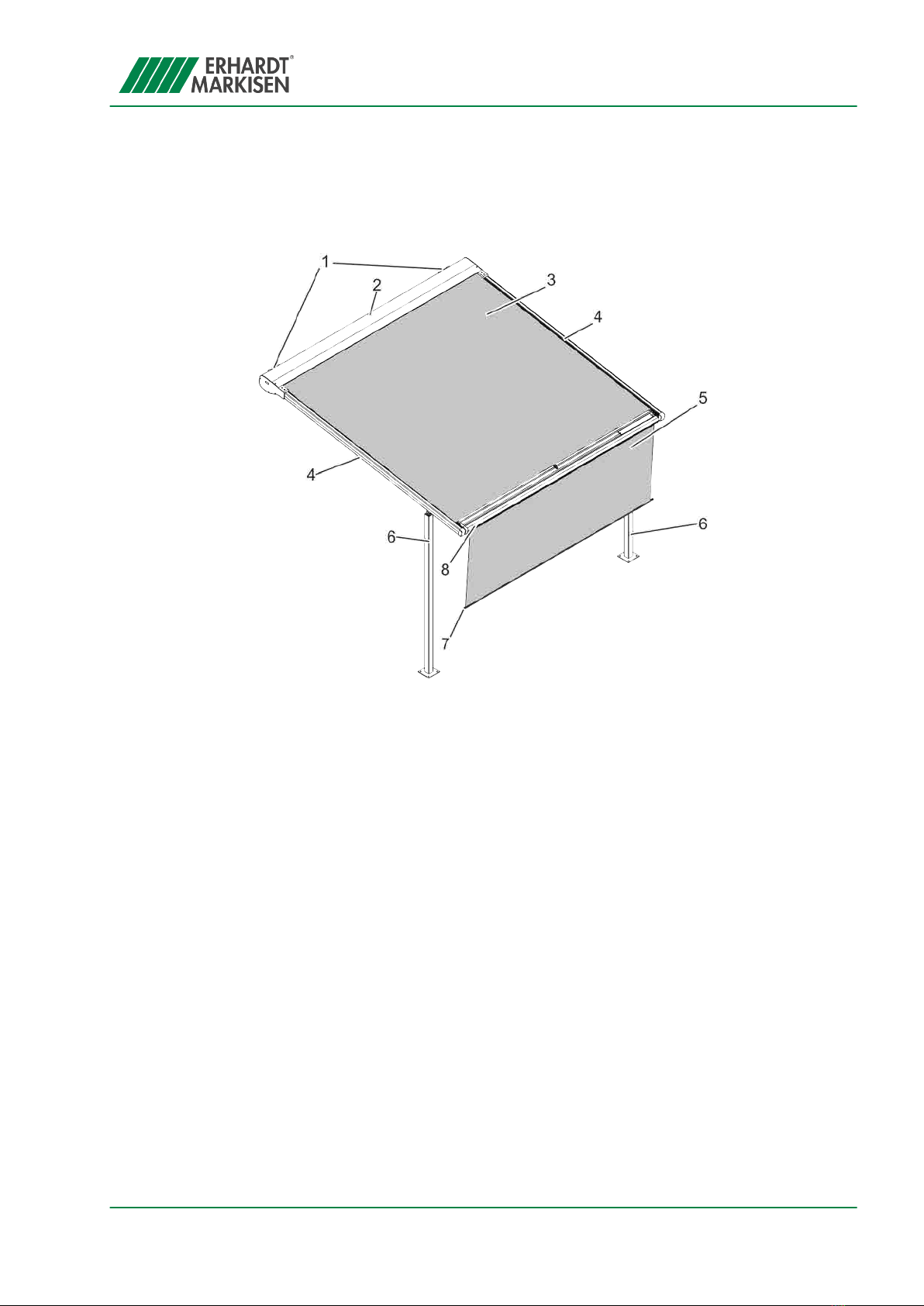
1 Overview
Fig. 1: Pergola awning PM21
1 Mounting brackets
2 Cassette
3 Canopy
4 Guide rail
5 Valance (optional)
6 Posts
7 Weighting bar
8 Drop bar
The pergola awning PM21 consists of a cassette (Fig. 1/2) in which
the rolled-up awning fabric (Fig. 1/3) is located. Lateral guidance of
the drop bar (Fig. 1/8) is provided by the two guide rails (Fig. 1/4).
The mounting brackets (Fig. 1/1) are fitted onto vertical surfaces
during installation. The cassette (Fig. 1/2) is affixed to the mounting
brackets (Fig. 1/1). The posts (Fig. 1/6) provide support at the
front.
If required, the valance (Fig. 1/5) can be lowered for additional
shading.
The awning is driven by a motor that can be operated using push-
buttons, a remote control or an automatic controller.
Optional ambient lighting for the awning is available in the form of
LED strips that are installed permanently in the cassette and/or the
guide rails; these can be dimmed. The ambient lighting is operated
using a radio remote control.
Setting up the PM21 pergola
awning
Lighting
Overview
13.12.2021 Pergola awning ERHARDT PM21 5
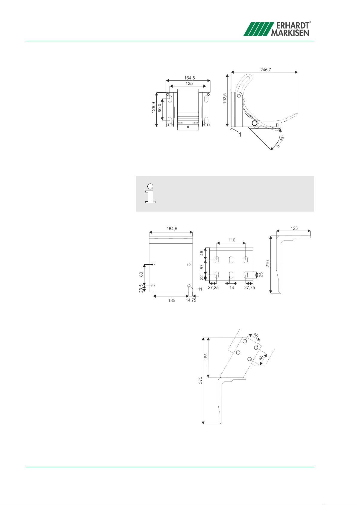
Fig. 2: Overview of wall console
1 Compensation plate
It may sometimes be necessary to use adapter
brackets (
Ä
page 6) when mounting the awning
on balcony projections, rafters or in soffits.
Fig. 3: Ceiling console
Fig. 4: Rafter console
Wall console
Ceiling console
Rafter console
Overview
13.12.2021 Pergola awning ERHARDT PM216

The posts can be embedded in concrete in a foundation or they
can be bolted onto a horizontal surface with the help of base
plates.
Erhardt recommends embedding the posts of the
PM21 in concrete. To do so, a corresponding foun-
dation must be created on site, according to the
dimensions of the PM21. The size, depth and rein-
forcement (Fig. 5) are recommendations from
Erhardt. The installing company bears full respon-
sibility for the on-site design.
Attachment elements!
The attachment elements are not included in the
scope of delivery.
The attachment elements have to be chosen on
site, depending on the foundation.
The base plate for the posts is anchored by four anchor bolts
(Fig. 6/1) to the compression-proof individual foundations (Fig. 6/2)
or, alternatively, it is anchored on a reinforced concrete slab.
The guide rail (Fig. 7/1) is bolted onto the post (Fig. 7/2) with the
help of the swivel mount (Fig. 7/3).
Posts
Fig. 5: Post foundation
Fig. 6: Post attachment with base
plate
Swivel mount (standard)
Fig. 7: Swivel mount
Overview
13.12.2021 Pergola awning ERHARDT PM21 7


2 Safety
Safety notes in these instructions are indicated by symbols. The
safety notes begin with signal words that indicate the magnitude of
the hazard.
DANGER!
This combination of symbol and signal word indi-
cates an imminently hazardous situation that will
result in death or serious injury if it is not avoided.
WARNING!
This combination of symbol and signal word indi-
cates a potentially hazardous situation that can
result in death or serious injury if it is not avoided.
NOTICE!
This combination of symbol and signal word indi-
cates a potentially hazardous situation that can
result in property damage if it is not avoided.
This symbol highlights useful tips and recommen-
dations as well as information designed to ensure
efficient and smooth operation.
Safety instructions may refer to specific, individual instructions.
Such safety instructions are integrated into the instruction so that
they do not interrupt the flow of reading when carrying out the task.
The signal words described above are used.
Example:
1. Loosen the screw.
2.
CAUTION!
Risk of pinching by cover!
Close the cover carefully.
3. Tighten the screw.
Safety note design
Tips and recommendations
Safety instructions in specific
instructions
Safety
13.12.2021 Pergola awning ERHARDT PM21 9

The following symbols are used in this manual to highlight instruc-
tions, results, lists, references and other elements:
Symbol Explanation
Step-for-step instructions
ðResults of instruction steps
References to sections in this manual and
to other applicable documents
Lists without a specified sequence
DANGER!
Risk of injury due to electrical current!
The lighting is powered by electric current. Work
performed improperly on the lighting can result in
serious or fatal injury.
– Electrical installations or repairs may only be
carried out by electricians.
– Do not allow any fluids to enter the lighting.
– Do not use flammable cleaning agents.
WARNING!
Risk of injury due to electrical current!
Work performed improperly on the awning’s elec-
trical components can result in serious or fatal
injury.
– Work on the electrical components must be per-
formed by qualified electricians only.
– The awning may only be connected if the speci-
fications on the type plate match the power
supply voltage.
– Observe the enclosed motor operating manual.
Additional symbols
Risk of injury due to electrical cur-
rent
Electrical current (with electric
drive)
Safety
13.12.2021 Pergola awning ERHARDT PM2110

WARNING!
Risk of burning during operation of the
lighting!
If the lamps are touched during operation, there is
an acute risk of burning.
– Do not touch lamps when they are in operation.
– Let lamps cool down before touching them.
WARNING!
Risk of damage to eyes due to direct eye con-
tact with the lamp
Longer eye contact with a switched-on lamp can
damage the eyes.
– Avoid direct eye contact with the lamp.
WARNING!
Risk of injury due to falling from heights!
Working at heights and on climbing aids poses a
risk of injury due to falling.
–Use suitable safety gear.
– Never fasten or lean climbing aids on the
awning.
– Make sure that climbing aids are standing firmly
and provide sufficient support.
– Never hold on to the awning.
WARNING!
Hazard posed by lifting the awning!
When lifting the awning, e.g. using ropes, there is
a risk of fatal injury through crushing.
– Securely attach the ropes to the awning.
– Make sure that the awning cannot slip free of
the ropes.
–Keep the awning horizontal when lifting it.
– Do not enter the danger zone beneath the load.
Risk of burning
Risk of damage to eyes
Danger of falling
Lifting using ropes
Safety
13.12.2021 Pergola awning ERHARDT PM21 11
WARNING!
Risk of injury due to improper disassembly or
reassembly!
Improper disassembly or reassembly poses an
increased risk of injury due to moving parts or
working at height.
– Have disassembly/reassembly be performed
only by a qualified fitter.
–If reassembly is planned, make sure that all of
the awning’s documentation is available.
Request any missing documents from Erhardt.
– Make sure sufficient space is available before
beginning work.
– Handle exposed, sharp-edged components with
care.
– Keep the workspace tidy and clean! Loosely
stacked or scattered components and tools
pose a risk of accident.
– Disassemble components properly. Note that
some of the components are heavy. If neces-
sary, use lifting gear.
– Secure components to prevent them from falling
or toppling over.
– Consult Erhardt in any cases of doubt.
NOTICE!
Risk of property damage when extending the
awning!
When extending the awning, there is a risk of dam-
aging it if the awning collides with obstacles.
– Remove fallen leaves and other foreign objects
from the awning.
–Do not extend the awning in freezing weather or
when it is snowing.
–Remove any obstacles.
Disassembling or reassembling old
systems
Extending the awning
Safety
13.12.2021 Pergola awning ERHARDT PM2112
Qualified fitter
A qualified fitter has the technical skills and experience as well as
knowledge of the applicable standards and regulations required to
perform work on shading systems and to recognise and avoid
potential hazards.
The qualification includes:
nKnowledge of health and safety, industrial safety and accident
prevention regulations
nAssessment of building fabric
nSafe handling of ladders and scaffolds
nSafe handling and transport of long, heavy components
nSafe handling of tools and machines
nCorrect installation of attachment elements
nCommissioning and operating the product
The permanent electrical wiring must be installed
by an officially qualified electrician only.
Industrial helmet
Industrial helmets protect the head against falling objects, swinging
loads and impacts with fixed objects.
Safety goggles
Safety goggles protect your eyes from flying parts and spraying liq-
uids.
Safety shoes
Safety shoes protect the feet from crushing, from dropping parts,
and from slipping on slippery floors.
Qualified persons
Personal protective equipment
Safety
13.12.2021 Pergola awning ERHARDT PM21 13
3 Preparing assembly
3.1 Preparing installation
ESD protection
Observe the ESD protection during awning
assembly! This can be done by wearing ESD
gloves, for example.
At least two people are required to assemble the
awning.
Personnel: nQualified fitter
Protective equipment: nIndustrial helmet
nSafety shoes
nSafety goggles
1. Check that the scope of delivery is complete:
Single system
nCassette with awning fabric and drop bar
n2 × guide rail
n2 x post with swivel mount
n2 × wall console
nDepending on the assembly situation:
–Rafter holders
–Ceiling console
Optional
nLighting (integrated in the cassette and/or the guide rails)
nPurlin
nPerforated plate
2. Make sure that the bearing surface has sufficient bearing
capacity.
Preparing assembly
Preparing installation
13.12.2021 Pergola awning ERHARDT PM2114
3.
Suitable fastening materials
–When installing outdoors, use stainless
steel screws.
–In the vicinity of swimming pools, use
galvanised steel screws to counter the risk
of corrosion posed by higher chlorine con-
tent in the air.
–To prevent contact corrosion, do not use
steel and stainless steel parts together.
Keep suitable fastening materials to hand (not included in
scope of supply).
Preparing assembly
Preparing installation
13.12.2021 Pergola awning ERHARDT PM21 15
4 Mounting the awning
4.1 Mounting the wall console
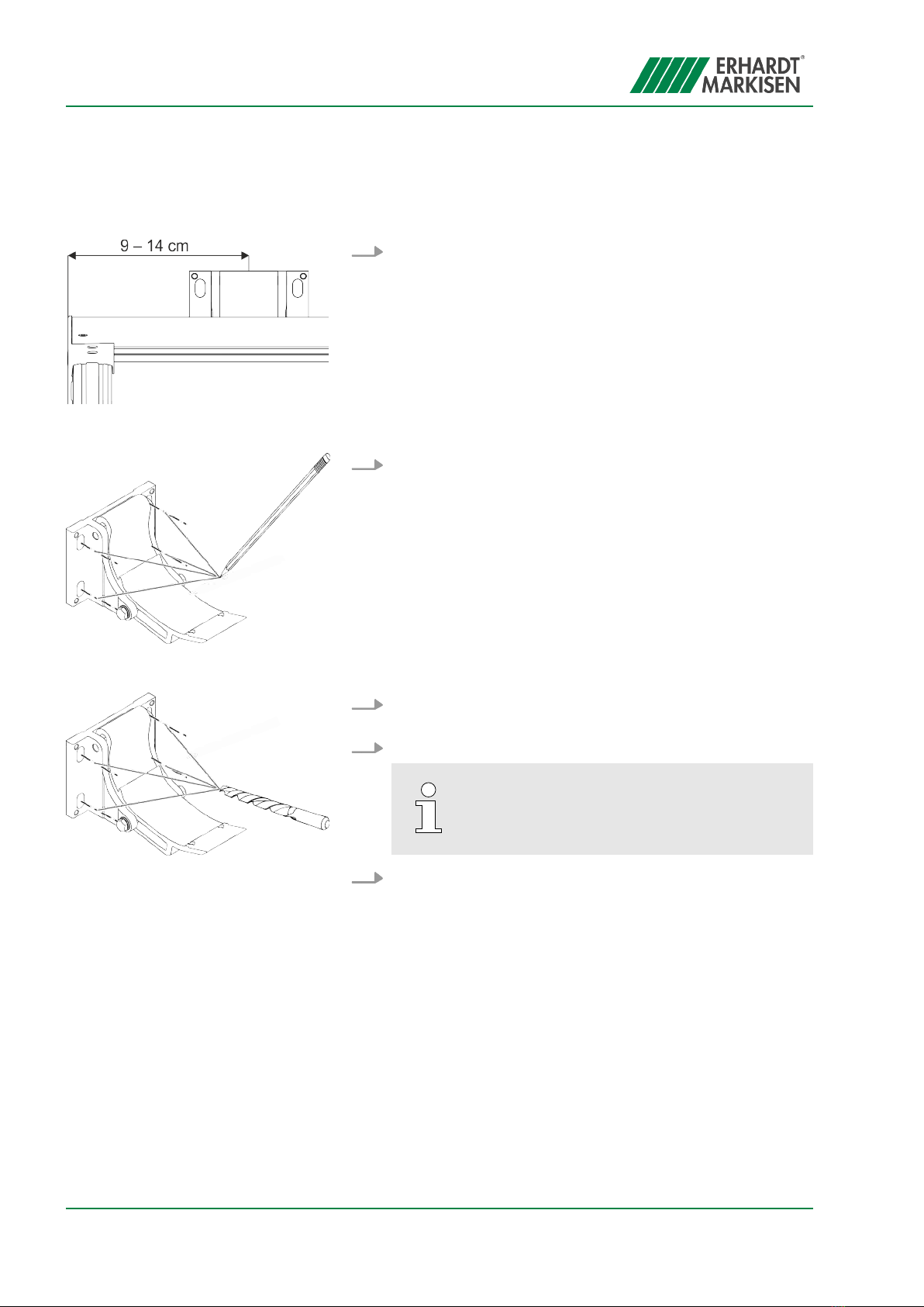
1. Determine the position of the wall consoles.
When determining the mounting height, note the headroom
and the tilt angle of the awning.
2. Transfer the holes for the wall console (Fig. 10).
3. Drill the holes (Fig. 11) and choose fastening materials
according to the mounting surface.
4. Screw the wall console onto the compensation plate.
The fastening material is not included in the
scope of supply.
5. Repeat steps 2 to 4 on all the wall consoles.
Fig. 9: Position of wall console
Fig. 10: Transferring the holes
Fig. 11: Drilling the holes
Mounting the awning
Mounting the wall console
13.12.2021 Pergola awning ERHARDT PM2116

4.2 Mounting the ceiling console
1. Determine the position of the ceiling consoles.
When determining the mounting height, note the headroom
and the tilt angle of the awning.
2. Transfer the holes for the ceiling console (Fig. 13).
3. Drill the holes (Fig. 14) and choose fastening materials
according to the mounting surface.
4. Screw on the ceiling consoles.
The fastening material is not included in the
scope of supply.
5. Repeat steps 2 to 4 on all the ceiling consoles.
Mounting the ceiling console
Fig. 12: Position of ceiling console
Fig. 13: Transferring the holes
Fig. 14: Drilling the holes
Mounting the awning
Mounting the ceiling console
13.12.2021 Pergola awning ERHARDT PM21 17
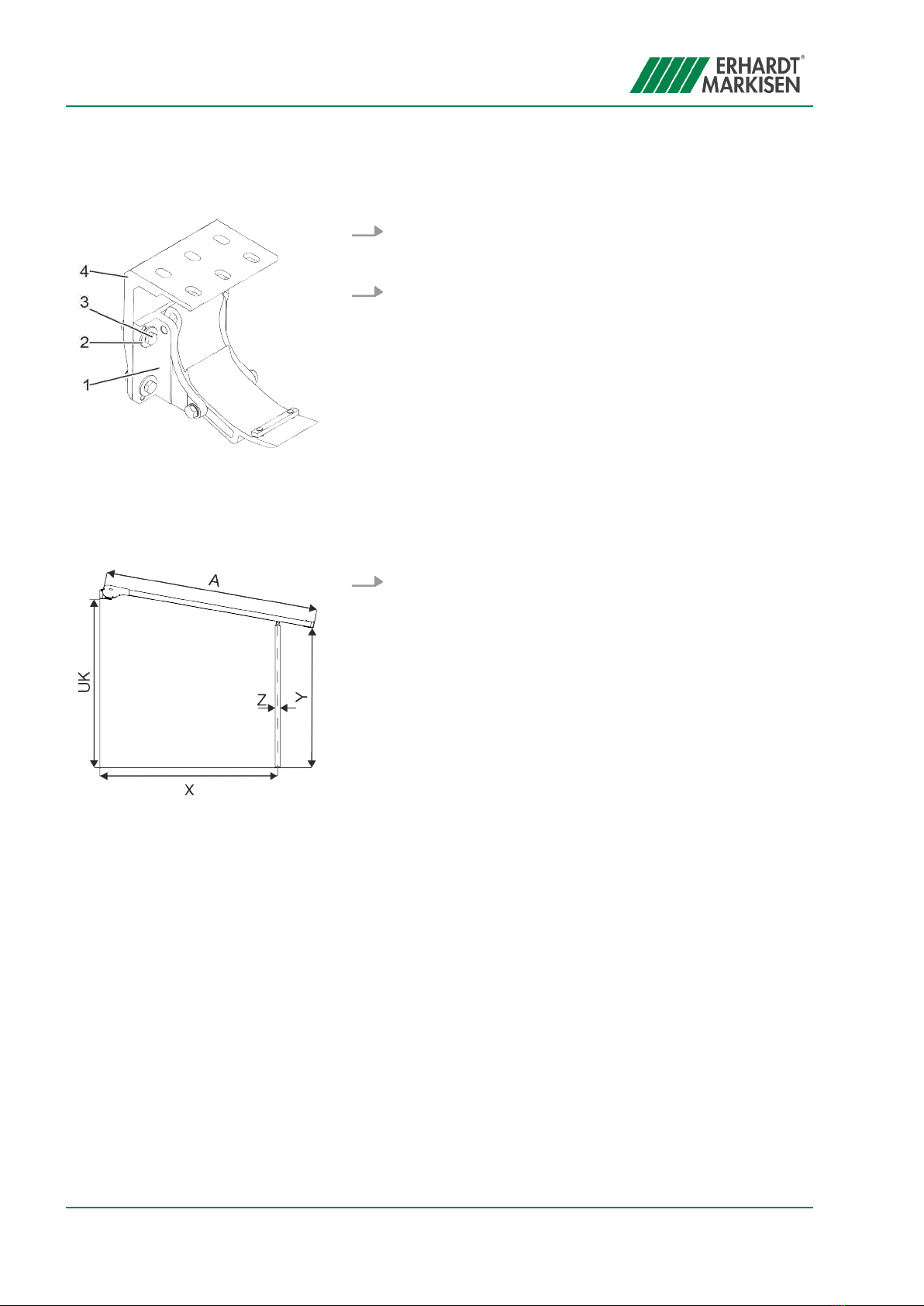
6. Screw the wall console (Fig. 15/1) onto the ceiling console
(Fig. 15/4) using 4 × hexagonal screw M10×30 (Fig. 15/3)
and washer DIN 125 Ø 13 (Fig. 15/2).
7. Screw all other wall consoles onto the ceiling consoles.
4.3 Mounting the posts
1. Determine the distance from the wall (Fig. 16/X) and mark it.
Screwing the wall console onto the
ceiling console
Fig. 15: Screwing on the wall console
Determining the position of the
posts
Fig. 16: Distance from wall
A Projection (max. 500 cm)
UK Lower edge of wall console
X The distance is calculated from
the projection (A) and the head-
room (Y) (max. 450 cm).
Y Headroom (min. 180 cm)
Z Post width 6.6 cm
Mounting the awning
Mounting the posts
13.12.2021 Pergola awning ERHARDT PM2118
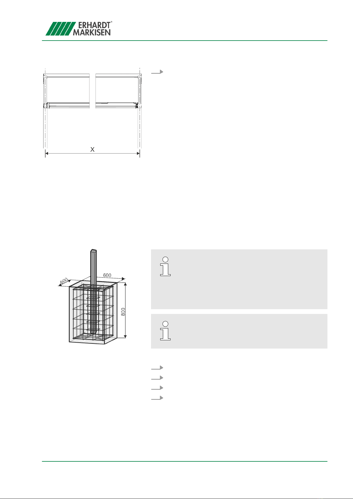
2. Determine the distance between the post axes (Fig. 17/X)
and mark it.
The posts can be installed in three different ways:
n
Ä
“Post with foundation” on page 19
n
Ä
“Posts with base plate” on page 20
n
Ä
“Post with steel base for purlin mounting (optional)”
on page 20
Erhardt recommends embedding the posts of the
awning in concrete. To do so, a corresponding
foundation must be created on site, according to
the dimensions of the awning. The size, depth and
reinforcement (Fig. 18) are recommendations from
Erhardt. The installing company bears full respon-
sibility for the on-site design.
If posts are mounted in a foundation, a water
drainage hole (diameter = 10 mm) must be created
just above ground level.
1. Insert the posts into the foundation.
2. Make sure that the posts are vertical and centred.
3. Secure the posts against falling and shifting.
4. Pour in the foundation.
Fig. 17: Distance between post axes
X System width minus 66 mm
Post with foundation
Fig. 18: Post foundation
Mounting the awning
Mounting the posts
13.12.2021 Pergola awning ERHARDT PM21 19
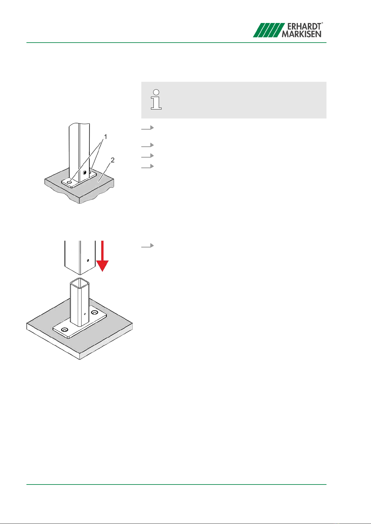
Do not fasten the posts until the guide rails
(
Ä
“Aligning the guide rails” on page 29) have
been aligned.
1. Copy the hole pattern for the base plate (Fig. 19/1) to the
bearing surface (Fig. 19/2).
2. Drill the mounting holes.
3. Insert the wall plugs.
4. Screw the base plate tight.
ðThe post is installed.
1. Place the post on the steel base.
Posts with base plate
Fig. 19: Base plate hole pattern
Post with steel base for purlin
mounting (optional)
Fig. 20: Placing the post
Mounting the awning
Mounting the posts
13.12.2021 Pergola awning ERHARDT PM2120
Table of contents
Other Erhardt Markisen Lawn And Garden Equipment manuals

Popular Lawn And Garden Equipment manuals by other brands

Exmark
Exmark QUEST Operator's manual

Algreen Products
Algreen Products Madison quick start guide

ABSCO SHEDS
ABSCO SHEDS 30152SECOK Assembly & instruction manual

Gardigo
Gardigo Vogel-Bar instruction manual

Makita
Makita UM164D Series instruction manual

FPM Agromehanika
FPM Agromehanika 618 192 INSTALLATION/HANDLING/MAINTENANCE


