Erickson 07508 User manual

Item no: 07508
1/6
Motorcycle Carrier
To avoid personal injury and/or property damage, please read and follow
ALL instructions before assembling and operating.
1. Never overload ramp or carrier. Maximum capacity for this motorcycle carrier is 500 lb /or hitch
capacity, whichever is less. Please refer to your hitch manufacturer’s maximum load capacity.
2. Carefully roll vehicle up or down the ramp. Never drive or ride your equipment while loading or
unloading. Erickson Manufacturing is not responsible for any damage or injuries that can
occur when loading and un-loading. USE AT YOUR OWN RISK!
3. Always load or unload on a solid, level and stable surface with the vehicle in gear, the parking/
emergency brake on, and engine off.
4. Use to haul a motorcycle or scooter only.
5. Ramp surface must be clean, dry and free from oil, grease or water.
6. Inspect ramp and carrier before each use. Tighten any loose hardware. Replace any worn/damaged
parts. Do not attempt to use if the ramp or carrier is damaged in any way. No modification, alteration,
or deviation to the motorcycle carrier are authorized by the manufacturer. Proper care and
maintenance of the unit are essential to safety.
7. Proper use of this product is critical to safety, and beyond the control of Erickson Manufacturing
Ltd. Erickson Manufacturing Ltd. neither guarantees nor is liable for any damage resulting from
improper use.The liability of this product is limited to its purchase price if it proves to be defective
in material and/or workmanship.
NEVER RIDE ON YOUR EQUIPMENTWHEN LOADING OR UNLOADING
MAY CAUSE INJURY OR DEATH
WARNING
Specifications
Rated Capacity 500 lb.
44” x 76” x 7”Dimensions

2/6
10 x1
21 (x2)
12 (x2)
(x2)
11 (x2)
9x2
2(x2)
1(x2)
22(x4)
23(x1)
3(x8)
8x2
6(x4)
13 (x2)
14 (x4)
18 (x2)
x2
4(x10)
5 (x16)
7 (x4)
15 (x4)
20 (x4)
19 (x4)
24 (x1)
(x1)
17
(x1)
16
Parts
AdjustableWrench(2pc)
Size=030mm
Adjustable Wrench (x2)
(0-30mm)
(S=5)AllenWrench(1pc)
(S=5) Allen Wrench (x1)
Assembly Recommended Tools
Part#
1
2
3
4
5
6
7
8
9
10
11
12
Part#
13
14
15
16
17
18
19
20
21
22
23
24
QTY
2
2
8
10
16
4
4
2
2
1
2
2
QTY
2
4
4
1
1
2
4
4
2
4
1
1
DESCRIPTION
Ramp
U-Type Connection Plate
3/8” x 13/4” Hex Bolt
3/8” Wider Washer
3/8” Locknut
1/2” x 71/2” Hex Bolt
1/2” Locknut
Clip
Hairpin
Supporting Bridge
Supporting Bar
L-Type Steel Plate
DESCRIPTION
3/8” x 5” Hex Bolt
3/8” x 3” Hex Bolt
3/8” Washer
Left Plate
Right Plate
3/8” x 31/4” Hex Bolt
10-Washer
5/16” Locknut
Storage Bracket
5/16” x 3/5” Hex Socket Bolt
Ramp
C-Type Safety Pin

Item no: 07508
3/6
Assembly
STEP 1 - Use U type connection plate (2)to put ramps(1) (2pcs) together. Assemble the ramps and U plate by
using 3/8”*1-3/4”hex bolt(3),3/8”wider washer (4) and 3/8”Locknut(5). Use 1/2”*7-1/2”Hex bolt(6) and 1/2”Lock-
nut(7), clip(8) and hairpin(9) to secure the ramp as shown in FIG1.
Fig.1

4/6
Tools Required for Assembly
STEP 4 Place the storage bracket(21) on the plates(16,17), align the holes, use 5/16”*3/5”hex socket cup head
bolt(22) and 5/16”Locknut(20)to tighten the parts as shown in FIG4.
Fig.4
STEP 2 - Place the ramp from Step 1 on top of the supporting bridge(10), use 3/8”*5”Hex bolt(13),3/8”washer (4)
and 3/8”Locknut(5) to secure L type steel plate(12) under the supporting ridge(11). Use 3/8”*3”Hex bolt(14),3/8”
washer (15) and 3/8”Locknut(5) to secure the supporting ridge(11) and L type steel plate(12). Screw all the
3/8”Locknut tight as shown in FIG2.
STEP 3 Use 3/8”-washer (19), 3/8”*3-1/4”Hex bolt(18) and 3/8”Locknut(5) to tighten left plate(16) and right
plate(17) to the supporting bridge(10) as shown in FIG3.
Fig.2
Fig.3

Item no: 07508
5/6
STEP 5 Put ramp(23) the place shown in FIG 5, fix it by using C type safety pin(24). Remove C type safety pin (24)
when using by putting ramp(23) on either side of the ramp(1) as shown in FIG6.
Fig.5
Fig.6
Installation
Step 1: Install assembled Motorcycle Carrier into a properly installed hitch (hitch & pin not included).
Step 2: Remove pin (24) and move ramp (23) away from the main unit.
Step 3: As shown in (Fig.6) place either end of ramp (23) into the ledge of part C. Rest the opposite end of the
ramp (23) on the ground to create a slope.
Step 4: With a partner, safely guide the wheels of the vehicle up the slope of the ramp. Adjust the bolts (8)
as necessary to fit different wheel sizes
Step 5: Use weight appropriate motorcycle ratchet straps (not included) to secure the vehicle to the anchor
points on the unit. Secure front and rear tires with lashing straps.
Step 6: Remove the ramp (23) and secure it to the unit with the pin (24).

Item no: 07508
6/6
Warranty Qualifications
Effective from the day you purchase the product. Please keep your dated purchase invoice as proof.
Repair/Replacement Warranty
Erickson Manufacturing Ltd. warrants to the original purchaser that the mechanical components
will be free of defect in material and workmanship for 90 days from the original date of purchase.
Transportation charges on product submitted for repair or replacement under warranty are the
sole responsibility of the purchaser. This warranty only applies to the original purchaser and is
not transferable.
Do Not ReturnThe Unit to the Place of Purchase
Contact Erickson Manufacturing Ltd’sTechnical Service and service people will troubleshoot any issue via phone or
email. Repairs or replacements without prior authorization, or at an unauthorized repair facility, will not be
covered by this warranty.
Warranty Exclusions
This warranty does not cover the following repairs and equipment:
Normal Wear
This warranty does not cover the repair when use has exhausted the life of a part or the equipment
as a whole.
Installation, Use and Maintenance
This warranty will not apply to parts and/or labor if this product is deemed to have been misused,
neglected, involved in an accident, abused, loaded beyond specifications, modified, or installed
improperly. Normal maintenance is not covered by this warranty.
Other Exclusions
This warranty excludes:
• Cosmetic defect such as paint, decal etc.
• Wear items
• Accessory parts
• Failures due to acts of God and other force majeure events beyond the manufacturer’s control.
• Problems cause by parts that are not Erickson Manufacturing Ltd. parts.
Limits of implied Warranty and Consequential Damage
Erickson Manufacturing Ltd. disclaims any obligation to cover any loss time, use of this product, freight, or any
incidental or consequential claim by anyone from using this product.THIS WARRANTY IS IN LIEU OF ALL OTHER
WARRANTIES EXPRESS OR IMPLIED, INCLUDING WARRANTIES OF MERCHANTABILITY OR FITNESS FOR A PAR-
TICULAR PURPOSE. A unit provided as exchange will be subject to the warranty of the original unit. The length of
the warranty governing the exchanged unit will remain calculated by reference to the purchase date of the original
unit.This warranty gives you certain legal rights which may change from state to state.Your state and/or
province may also have other right you may be entitled to that are not listed within this warranty.
Contact Information
Marine City, Michigan 48039
Thamesville, Ontario N0P 2K0
Toll Free: 1-888-546-4668
Warranty
Table of contents
Popular Motorcycle Accessories manuals by other brands
Viper
Viper BL+ instruction manual
Paaschburg & Wunderlich
Paaschburg & Wunderlich SHIN YO TEXAS Mounting and safety instructions
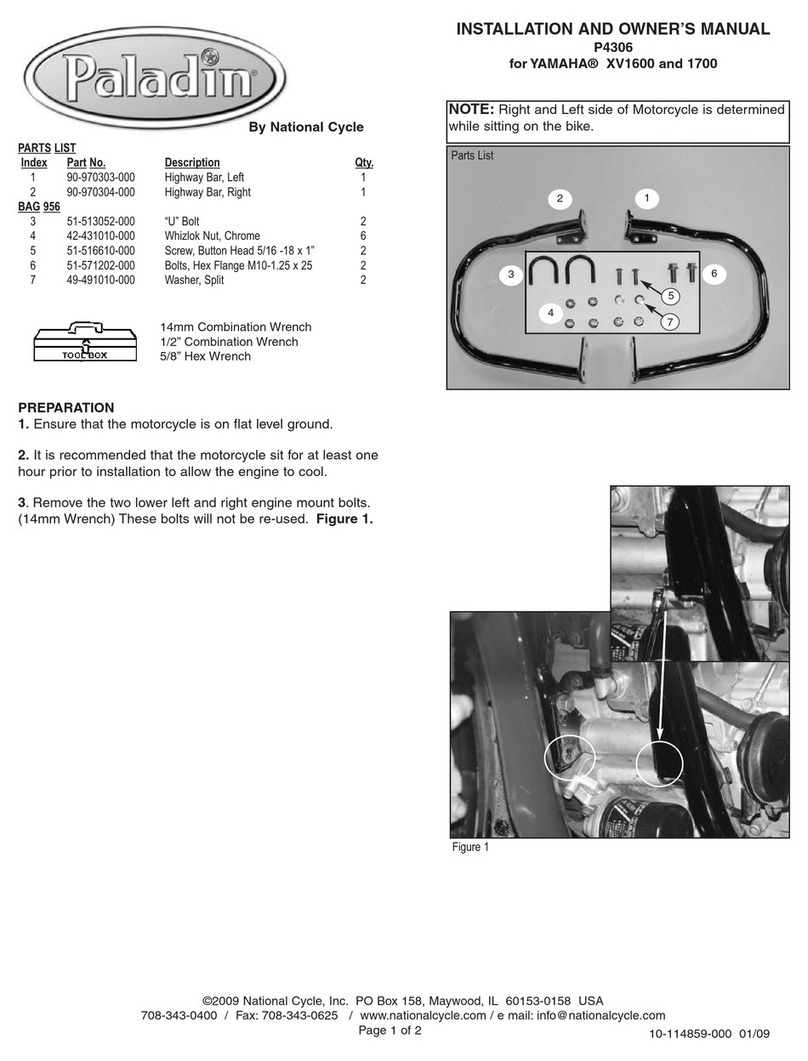
National Cycle
National Cycle Paladin P4306 Installation and owner's manual
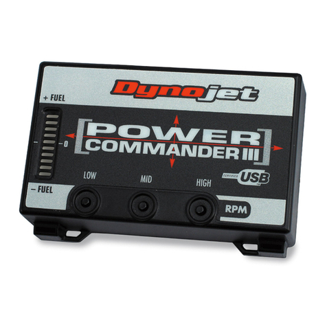
Dynojet
Dynojet Power Commander III installation instructions
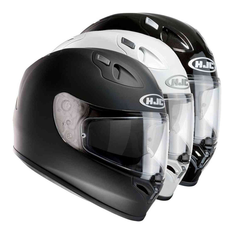
HJC
HJC FG-ST owner's manual
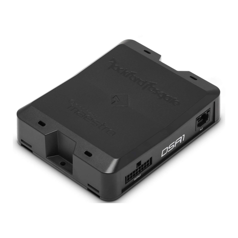
Rockford Fosgate
Rockford Fosgate DSR1 instructions
CDI
CDI 114-4952A30 Installation and troubleshooting guide
hepco & becker
hepco & becker 6302536 00 01 quick start guide
Performance Machine
Performance Machine Vision Series Assembly instructions
Gazzini
Gazzini 10030234 Instructions for use
TUV Rheinland
TUV Rheinland crivit SP-803Y instruction manual
BMW
BMW K 1200 LT manual
