Ericsson GE MASTR II 19A149979P1 User manual

Mobile Communications
MASTR®
II BASE STATION
12/24V POWER SUPPLY
19A149979P1 - 120 VOLT/60 Hz
19A149979P2 - 230 VOLT/50 Hz
WARNING: TO PREVENT FIRE OR ELECTRIC SHOCK HAZARD. DO
NOT EXPOSE THIS PRODUCT TO RAIN OR MOISTURE.
CAUTION: TO PREVENT ELECTRIC SHOCK DO NOT USE THIS (PO-
LARIZED) PLUG WITH AN EXTENSION CORD, RECEPTACLE OR
OTHER OUTLET UNLESS THE BLADES CAN BE FULLYINSERTED
TO PREVENT BLADE EXPOSURE.
THESE SERVICING INSTRUCTIONS ARE FOR USE BY QUALI-
FIED PERSONNEL ONLY. TOAVOID ELECTRIC SHOCK DO NOT
PERFORM ANY SERVICING OTHER THAN THAT CONTAINED IN
THE OPERATING INSTRUCTIONS UNLESS YOU ARE QUALI-
FIED TO DO SO. REFER ALL SERVICING TO QUALIFIED SERV-
ICE PERSONNEL
CAUTION
Maintenance Manual
LBI-38551

Copyright © January 1992, Ericsson GE Mobile Communications Inc.
TABLE OF CONTENTS
Page
SPECIFICATIONS . . . . . . . . . . . . . . . . . . . . . . . . . . . . . . . . . . . . . . . . . . . . . . . . . . 3
IMPORTANT SAFETY INFORMATION . . . . . . . . . . . . . . . . . . . . . . . . . . . . . . . . . . . . . . 4
DESCRIPTION . . . . . . . . . . . . . . . . . . . . . . . . . . . . . . . . . . . . . . . . . . . . . . . . . . . . 6
CIRCUIT ANALYSIS . . . . . . . . . . . . . . . . . . . . . . . . . . . . . . . . . . . . . . . . . . . . . . . . . 6
MAINTENANCE . . . . . . . . . . . . . . . . . . . . . . . . . . . . . . . . . . . . . . . . . . . . . . . . . . . 7
OUTLINE DIAGRAM . . . . . . . . . . . . . . . . . . . . . . . . . . . . . . . . . . . . . . . . . . . . . . . . 12
ASSEMLBY DIAGRAMS
60 Hz Power Supply . . . . . . . . . . . . . . . . . . . . . . . . . . . . . . . . . . . . . . . . . . . . . . . 13
50 Hz Power Supply . . . . . . . . . . . . . . . . . . . . . . . . . . . . . . . . . . . . . . . . . . . . . . . 16
SCHEMATIC DIAGRAMS
60 Hz Power Supply . . . . . . . . . . . . . . . . . . . . . . . . . . . . . . . . . . . . . . . . . . . . . . . 14
50 Hz Power Supply . . . . . . . . . . . . . . . . . . . . . . . . . . . . . . . . . . . . . . . . . . . . . . . 17
PARTS LIST
60 Hz Power Supply . . . . . . . . . . . . . . . . . . . . . . . . . . . . . . . . . . . . . . . . . . . . . . . 15
50 Hz Power Supply . . . . . . . . . . . . . . . . . . . . . . . . . . . . . . . . . . . . . . . . . . . . . . . 18
LBI-38551
2

SPECIFICATIONS*
OUTPUT VOLTAGE
Transmit and Receive Simultaneously 26.0 Vdc±1.0 Vdc @ 15 Amps (F801A)
13.0Vdc ±0.5Vdc @ 3Amps (J801)
Receive only Vdc @ 3 Amps (J801)
INPUT VOLTAGE 121 Vac ±20% (60 Hz version)
230 Vac ±15% (50 Hz version)
INPUT FREQUENCY 60 Hz ±2 Hz (60 Hz version)
50 Hz ±2 Hz (50 Hz version)
NOTE: For every + 1.0% change in the input frequency, the output voltage will not vary
more than + 1.6% from the output voltage measured at the nominal input line frequency.
INPUT LINE SURGE PROTECTION 150 V rated MOV (60 Hz version)
275 V rated MOV (50 Hz version)
DUTY CYCLE
For 0-18 Amp output 100% (Continuous Duty)
OUTPUT VOLTAGE RIPPLE < mV p-p @ 25°C
< mV p-p @ -30°C
OUTPUT TRANSIENT RESPONSE
Overshoot Not to exceed 30 Volts (F801A)
Undershoot Not less than 22 Volts (F801A)
EFFICIENCY 70% @ rated TX/RX load current and nominal line voltage
FUSE CAPABILITY
Input 10 Amp (60 Hz version)
(2) 5 Amp (50 Hz version)
Output 5 Amp (Low Current Port)
20 Amp (High Current Port)
DIMENSIONS (HxWxD) 5.25" x 19" x 10.35"
WEIGHT 45 lbs.
OPERATING ENVIRONMENT -30°C To + 60°C
* These specifications are intended primarily for the use of the service personnel.
LBI-38551
3

IMPORTANT SAFETY INFORMATION
1. SAVE THIS MANUAL - It contains important
safety and operating instructions.
2. Before using the product, please follow and adhere
to all warnings, safety and operating instructions
located on the product and in the manual.
3. DO NOT expose product to rain, snow or other
type of moisture.
4. Care should be taken so objects do not fall or liq-
uids do not spill into the product.
5. DO NOT expose product to extreme temperatures.
6. DO NOT use auxiliary equipment not recom-
mended or sold by the manufacturer.To do so may
result in a risk of fire, electric shock or injury to
persons.
7. To reduce risk of damage to electrical cord, pull by
plug rather than cord when disconnecting unit.
8. Make sure the cord is located so it will not be
stepped on, tripped over or otherwise subjected to
damage or stress.
9. An extension cord should not be used unless abso-
lutely necessary. Use of an improper extension
cord could result in a risk of fire and electric
shock. If an extension cord must be used, make
sure:
a. That pins on the plug of the extension cord are
the same number, size and shape as those of
the plug on the power supply.
b. That the extension cord is properly wired in
good condition, and
c. That the wire size is large enough for AC am-
pere rating of unit.
10. DO NOT operate unit with a damaged cord or plug
- replace them immediately.
11. DO NOT operate this product in an explosive at-
mosphere unless it has been specifically certified
for such operation.
12. To reduce risk of electric shock, unplug unit from
outlet before attempting any maintenance or clean-
ing.
13. DO NOT operate this product with covers or pan-
els removed. This unit does not contain any user
serviceable components.
14. Use only fuses of the correct type, voltage rating
and current rating as specified in the parts list. Fail-
ure to do so can result in fire hazard.
15. GROUNDING AND AC POWER CORD CON-
NECTION - To reduce risk of electrical shock use
only a properly grounded outlet. The unit is
equipped with an electric cord having an equip-
ment - grounding conductor and a grounding plug.
Be sure the outlet is properly installed and
grounded in accordance with all local codes and
ordinances.
16. DANGER - Never alter the AC cord or plug. Plug
into an outlet properly wired by a qualified electri-
cian. Improper connection or loss of ground con-
nection can result in risk of an electrical shock.
17. The Model 19A149979P2 is for use on a circuit
having a nominal rating of 230 Vac and is factory
equipped with a specific electric cord to permit
connection to an acceptable electric circuit.A plug
meeting local electrical codes must be supplied by
the customer. Make sure the unit is connected to an
outlet having the same configuration as the plug.
No adapter should be used with this unit.
A ferroresonant power supply is designed to
work specifically at a given frequency. The 60
and 50 Hz supplies should be used at their
nominal frequency ±2 Hz.
NOTE
LBI-38551
4

Figure 1 - 60 Hz Power Supply (19A149979P1, Rev. A)
Figure 2 - 50 Hz Power Supply (19A149979P2, Rev. A)
LBI-38551
5

DESCRIPTION
The ERICSSON GE MASTR®
II Base Station 12/24
Volt Power Supply provides up to 429 watts to power a
MASTR II 800 or 900 MHz base station receiver, system
circuitry, and transmitter. The nominal 12 volt output is ac-
tually 13.0 Vdc and provides a maximum of 3 amperes to
power the receiver and system circuitry. The nominal 24
volt output is actually 26.0 Vdc and provides a maximum of
15 amperes to power the transmitter power amplifier.
The 60 Hz Model (19A149979P1) operates from a
nominal 121 Vac, 60 Hz source. If a 208/220/240Vac, 60 Hz
source is used, an external step-down transformer (similar
to 19C307148P1) must be used with the ’979P1supply. The
50 Hz model (19A149979P2) provides the same output as
the ’979P 1 supply, but operates from a nominal 230 Vac, 50
Hz source. The output voltage will change a maximum of +
1.6% for each + 1.0% change in the input line frequency.
The power supply’s step-down ferroresonant trans-
former provides excellent line voltage regulation. For the
rated input line voltage range ( ±20% for P1, ±15% for P2),
the output voltage will not vary more than 2 %. Aferroreso-
nant power supply provides inherently excellent line voltage
surge protection, and fewer parts for high reliability. No ac-
tive semiconductor devices are used which could reduce re-
liability.
The output voltages will vary depending on the load cur-
rents that the supply is being asked to source. As the load
current rises, the output voltage will drop. Typical output
voltages for various load currents are as follows:
The operation and servicing of the power supply are
completely accessible from the front. The ON/OFF switch
and all fuses are located on the front panel. The low profile
slot type fuse holders contain the primary fuse(s) F1 (F1 and
F4 for P2), the high current output fuse F2, and the low cur-
rent output fuse F3. The primary fuse(s) protect the input
wiring to the ferroresonant transformer (one 10 amp fuse for
P1, two 5 amp fuses for P2). The output fuses F2 (20 amps)
and F3 (5 amps) provide external overload protection.
The 60 Hz supply provides a courtesy dual AC recepta-
cle. The primary line current fuse (F1) also provides over-
current protection for the dual receptacle. The 60 Hz supply
draws 5 amps under nominal conditions and 7 amps under
all conditions. Thus, the dual courtesy receptacles are rated
for 3 amps.
CIRCUITANALYSIS
In the 60 Hz power supply (’979P 1), the ON/OFF
switch (S1) provides line voltage to the power supply
through the primary line fuse F1. Line current flows through
F1 to the courtesy receptacle prior to S1. This allows line
voltage to always be available at the receptacles. Current
then flows through the primary of stepdown transformer
(T1) via the 200°C thermal fuse. The thermal fuse would
only open in the unlikely event that an internal short would
develop in the transformer. The varistor (VR1- 150 V rat-
ing) provides addition input line voltage suppression.
In the 50 Hz power supply (’979P2), the ON/OFF
switch (S1) is a DPST type switching both primary AC
lines. In addition, both input lines have 5 amp fuses (F1 and
F4). The varistor (VR1-275 Vrating) provides additional in-
put line voltage suppression. When power is applied, cur-
rent flows through the primary of step-down transformer
(T1) via the 200°C thermal fuse. As in the 60 Hz model, the
thermal fuse would only open if the transformer develops an
internal short.
The step-down transformer (T1) is a ferroresonant type
which has inherently good input line voltage regulation.
This eliminates the need for additional high current regula-
A ferroresonant power supply is designed to work
specifically at a given frequency. The 60 Hz and 50
Hz supplies should be used at their nominal fre-
quency ±2 Hz.
NOTE
LOAD CURRENT CONDITIONS 12 V OUTPUT 24 V OUTPUT
TX AND RX SIMULTANEOUSLY (15 + 3 AMPS) ~13.0 VDC ~26.0 VDC
RX ONLY (0 + 3 AMPS) <15.8 VDC <29.0 VDC
NO LOAD (0 + 0 AMPS) <16.3 VDC <30.0 VDC
LBI-38551
6

tors. C9 serves as a resonating capacitor across the secon-
dary taps of the transformer.
The transformer steps the input voltage down to ap-
proximately 28 Vac across two secondary windings. Each
winding drives two separate full wave bridge rectifiers con-
sisting of D1A, B through D4A, B. The rectifiers are dual
diode packages and are mounted on heat sink HS 1. During
the first half of the period diodes D1B, D2A,D3B, and D4A
are conducting and delivering current which is summed at
the input to the high current filter. During the second half of
the period diodes D1A, D2B, D3A, and D4B are conducting
and also delivering current which is summed at the input to
the high current filter. The high current filter consists of C1-
C4, C7, L1, and R1. It is designed to reduce the output rip-
ple to less than 100 mV p-p for any current load up to 15
amps. It also keeps transient responses greater than 22 volts
and less than 30 volts. Resistor R1 is a 30 ohm, 50 watt re-
sistor that serves two functions. One, it acts as a bleeder re-
sistor to discharge the capacitors when the supply is turned
off. Two, it provides a minimum current load to prevent the
output voltage from ever rising above 30 volts under any
load condition. The high current filter sources up to 15 amps
through the 20 amp fuse F2 to the high current output port
F801A on the rear wall of the chassis. F801A-1 and F801A-
2 are A+ and A-, respectively, and connect to the transmitter
power amplifier.
The two secondary windings are also center tapped to
produce a step-down voltage of around 14 Vac which is also
fed to the two full wave bridge rectifiers. During the first
half of the period, diodes D2A and D4A provide a conduc-
tion path for current going to both the high current filter and
the low current filter. During the second half of the period,
diodes D1A and D3A provide the conduction path for cur-
rent going to the high current filter and the low current fil-
ter. The low current filter consists of C5, C6, L2, and R2. It
is designed to reduce the output ripple to less than 100 mV
p-p for any current load up to 3 amps. It also keeps transient
responses greater than 11 volts and less than 18 volts. Resis-
tor R2 is a 100 ohm, 10 watt resistor that serves two func-
tions. One, it acts as a bleeder resistor to discharge the
capacitors when the supply is turned off. Two, it provides a
minimum current load to prevent the output voltage from
ever rising above 18 volts under any load condition. The
low current filter sources up to 3 amps through the 5 amp
fuse F3 to the low current output port J801 on the rear wall
of the chassis. J801-1, 2, 3 and J801-4,5,6 are A+ and A-,
respectively, and connect to the receiver and system cir-
cuitry.
The power supply is rated for a nominal 26.0 Vdc for a
15 amp load out of F801A and for a nominal 13.0 Vdc for a
3 amp load out of J801 (receiving and transmitting simulta-
neously). When receiving only (a 3 amp load out of J801)
the output voltage is less than 15.8 Vdc at J801 and less
than 29.0 VDC at F801A.
MAINTENANCE
For disassembly, remove 8 screws and lift off top cover.
Disassembly is required before working on the power sup-
ply. When replacing any component be certain to use an
identical component. Thermal joint compound is required
between diodes D1, D2, D3, and D4 and the heat sink.
TROUBLE-SHOOTING
The trouble-shooting procedure in Table 1 may be help-
ful in isolating a defective component or assembly in a mal-
functioning power supply. When a component or assembly
is identified as defective, replace the defective component
with an identical component. Be sure to check associated
circuitry for any other damaged components before apply-
ing power to the unit.
ADJUSTMENTS
This power supply has no adjustments or controls other
than the ON/OFF switch.
INSTALLATION
The power supply is normally installed in an EIA 19
inch wide rack of a MII base station cabinet. It can also be
installed in a 19 inch wide stand alone open rack.
To avoid electrical shock, disconnect power supply
from the AC input power source before removing or
replacing any component or assembly.
WARNING
Insure that ventilation holes in the unit are not ob-
structed when the unit is mounted or in operation.
NOTE
LBI-38551
7

Figure 3 - 60 Hz Power Supply (19A149979P1, Rev. A)
Figure 4 - 50 Hz Power Supply (19A149979P2, Rev. A)
LBI-38551
8

FUSE REPLACEMENT
To replace a defective fuse, perform the following pro-
cedure:
1. Place ON/OFF switch to the OFF position.
2. For fuses F1 (F1 & F4 on ’979P2), F2, or F3; re-
move cap from fuse holder and replace fuse with a
fuse of the same type and rating.
To avoid possible electric shock, DO NOT operate
this power supply with the fuse cover removed.
WARNING
No one should be permitted to handle any portion of
the equipment that is supplied with high voltage, or
to connect any external apparatus to the units while
the units are supplied with power. KEEP AWAY
FROM LIVE CIRCUITS.
WARNING
LBI-38551
9

TROUBLESHOOTING PROCEDURES
SYMPTOM PROCEDURE
No output voltage at J801 Check the following:
1. Open F1, F3 or S1.
2. AC voltage on W801.
3. Open D1, D2, D3, or D4.
No output voltage at F801A Check the following:
1. Open F1, F2 or S1.
2. AC voltage on W801.
3. Open D1, D2, D3, or D4.
Low output voltage on F801A.
0 < Vo < 25.0 Vdc
Check the following:
1. If one of the dual diodes on D1, D2, D3, or D4 is shorted.
NOTE: All four diode packages contain two diodes each.
2. Line frequency < 60 Hz.
3. Load current greater than 15.0 amps.
Low output voltage on J801.
0 < Vo < 12.5 Vdc
Check the following:
1. If one of the dual diodes on D1, D2, D3, or D4 is shorted.
NOTE: All four diode packages contain two diodes each.
2. Line frequency < 60 Hz.
3. Load current greater than 3.0 amps.
High output voltage on F801A
(>30.0 Vdc) or J801 (>16.3 Vdc). Check the following:
1. R1 not connected between pos. 1 and 2 on F801A.
2. R2 not connected between pos. 1 and 4 on J801.
3. Line frequency >60 Hz.
Table 1 - 60 Hz Power Supply 19A149979P1
LBI-38551
10

TROUBLESHOOTING PROCEDURES
Printed in U.S.A.
SYMPTOM PROCEDURE
No output voltage at J801 Check the following:
1. Open F1, F3, F4 or S1.
2. AC voltage on W801.
3. Open D1, D2, D3, or D4.
No output voltage at F801A Check the following:
1. Open F1, F2, F4 or S1.
2. AC voltage on W801.
3. Open D1, D2, D3, or D4.
Low output voltage on F801A.
0 < Vo < 25.0 Vdc
Check the following:
1. If one of the dual diodes on D1, D2, D3, or D4 is shorted.
NOTE: All four diode packages contain two diodes each.
2. Line frequency < 50 Hz.
3. Load current greater than 15.0 amps.
Low output voltage on J801.
0 < Vo < 12.5 Vdc
Check the following:
1. If one of the dual diodes on D1, D2, D3, or D4 is shorted.
NOTE: All four diode packages contain two diodes each.
2. Line frequency < 50 Hz.
3. Load current greater than 3.0 amps.
High output voltage on F801A
(>30.0 Vdc) or J801 (>16.3 Vdc). Check the following:
1. R1 not connected between pos. 1 and 2 on F801A.
2. R2 not connected between pos. 1 and 4 on J801.
3. Line frequency >50 Hz.
Table 2 - 50 Hz Power Supply 19A149979P2
LBI-38551
11

PRINTED CIRCUIT BOARD
50 Hz AND 60 Hz MODELS
OUTLINE DIAGRAM
(33017704, Sh. 1)
(33017700, Sh. 1)
COMPONENT SIDE
(33017704, Sh. 1)
(33017700, Sh. 2)
SOLDER SIDE
LBI-38551
12
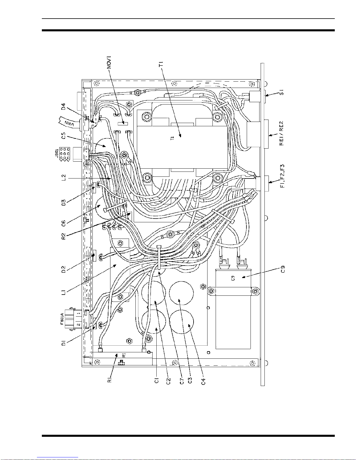
60 Hz POWER SUPPLY
19A149979P1, Rev. A
ASSEMBLY DIAGRAM LBI-38551
13

60 Hz POWER SUPPLY
19A149979, Rev A
(289PS3, Sh. 1, Rev. C)
SCHEMATIC DIAGRAMLBI-38551
14

PARTS LIST LBI-38551
15

50 Hz POWER SUPPLY
19A149979P2, Rev. A
ASSEMBLY DIAGRAMLBI-38551
16

50 Hz POWER SUPPLY
19A149979P2, Rev. A
(289PS4 Sh. 1, Rev. C)
SCHEMATIC DIAGRAM LBI-38551
17

PARTS LISTLBI-38551
18
This manual suits for next models
1
Table of contents
Other Ericsson GE Power Supply manuals


