Linergy SPY CENTER BASIC SCB050 Series User manual
VER .
1.0
SPY CENTER
BASIC
MANUAL
SERIES SCB050
SERIES SCB060
CENTRAL POWER SUPPLY SYSTEM
FOR INSTALLATIONS WITH CENTRALIZED
SUPPLY LUMINAIRES


Please strictly comply with all warnings and instructions indicated in this
operating manual.
Keep this manual properly for future reference and do not use this unit until you
have carefully read all the information and warnings described.

MANUAL
index
.
CHAPTER 1
Introduction
System description
Unpacking
Rules for connection
Local ventilation
CHAPTER 2
Rules for installation
Removal of the CPS and battery box
Local temperatures
Battery maintenance
CPS rear view
Electrical connections diagram
Connection example
NC / NO relay
CPS connection to the battery box
EPO
System on / off
CHAPTER 3
Display
LED signaling
Key function
Operation mode
CHAPTER 4
Comunication port
Intelligent slot
Power Manager
SCBLAN
SCBMOD
CHAPTER 5
Error reports
Failure reports
pg.1
pg.2
pg.3
pg.4
pg.5
pg.6
pg.7
pg.8
pg.9
pg.10
pg.11
pg.12
pg.13
pg.14
pg.15
pg.16
pg.18
pg.19
pg.19
pg.20
pg.24
pg.24
pg.25
pg.25
pg.26
pg.28
pg.28

1
INTRODUCTION
Thank you for choosing this product.
Before installing the CPS, read this manual carefully. This manual provides instructions for the safety,
installation and operation of the equipment. It also allows the most complete knowledge of the product
in order to obtain the best service from it.
Keep this manual.
WARNING!
The equipment described in this manual must be intended only for the use for which it was specifically
designed. Any other use is to be considered improper and dangerous.
The Central Power Supply of the SPY CENTER BASIC series, provide electrical continuity to all types
of users, in case of lack of the main power supply.
Specifically designed for power supply applications of emergency systems, they provide a pure sine
wave at the output, and allow different and various possibilities of load management thanks to
differentiated outputs.
ENVIROMENTAL
All our products comply with the objectives defined in the policy of the environmental management
system developed by the company in accordance with current legislation.
DISPOSAL OF THE PRODUCT
The CPS contains materials which in case of disposal are considered toxic and dangerous waste, for
example electronic cards and batteries. Treat these materials according to the laws in force by
contacting qualified personnel.
CHAPTER 1
In evaluating the packaging, the choice of material was made by choosing recyclable materials. For
correct disposal, please separate and identify the type of material making up the packaging. Dispose of
all materials according to the regulations in force in the country in which the product is used.

2
Symbols and Meaning
Symbols Meaning
Notice to the user
to pay special attention
High voltage hazard
Power ON
Shutdown OFF INVERTER
Shutdown CPS
Alternating current source (AC)
Direct current source (DC)
Ground protection
Audio alarm disabled
Overload indication
Battery
Recyclable
Do not disperse with ordinary waste
SYSTEM DESCRIPTION
This double conversion online unit ensures continuous power supply to emergency lighting systems or
security systems.
The double conversion system has the main feature of eliminating disturbances from the main network.
VFI (Voltage and Frequency Independent): in which the voltage at the rescuer's output is independent
of changes in the mains voltage and frequency variations are controlled within the limits prescribed by
the regulations.
A rectifier converts alternating current from the network into direct current. This current charges the
batteries and activates the INVERTER. Based on this current, the inverter generates a sinusoidal
alternating current that constantly supplies the loads.
Lighting or security systems are therefore powered entirely by the CPS. In the event of a power failure,
the batteries power the inverter.
This manual can be used for the model:
Ÿ Series SCB050
Ÿ Series SCB060
DESCRIPTION OF SYMBOLS
The following symbols shown may be displayed in the CPS during operation. Therefore, all users should
be familiar with it to understand its meaning.

3
UNPACKING AND INSPECTION
1) Unpack the packaging and check the contents inside.
The content of the packaging includes:
ŸThe CPS;
ŸThe manual;
ŸThe serial and USB communication cable
ŸCD with POWER MANAGER program
ŸBattery Box (with batteries connected)
ŸCable and fuse kit.
2) Check the appearance of the pallet at the time of delivery to make sure there were no damages
during transport.
If defects are found, notify them immediately to the carrier and the sender.
C P S
CD Power Manager
Kit cable + fuse
Box battery
4
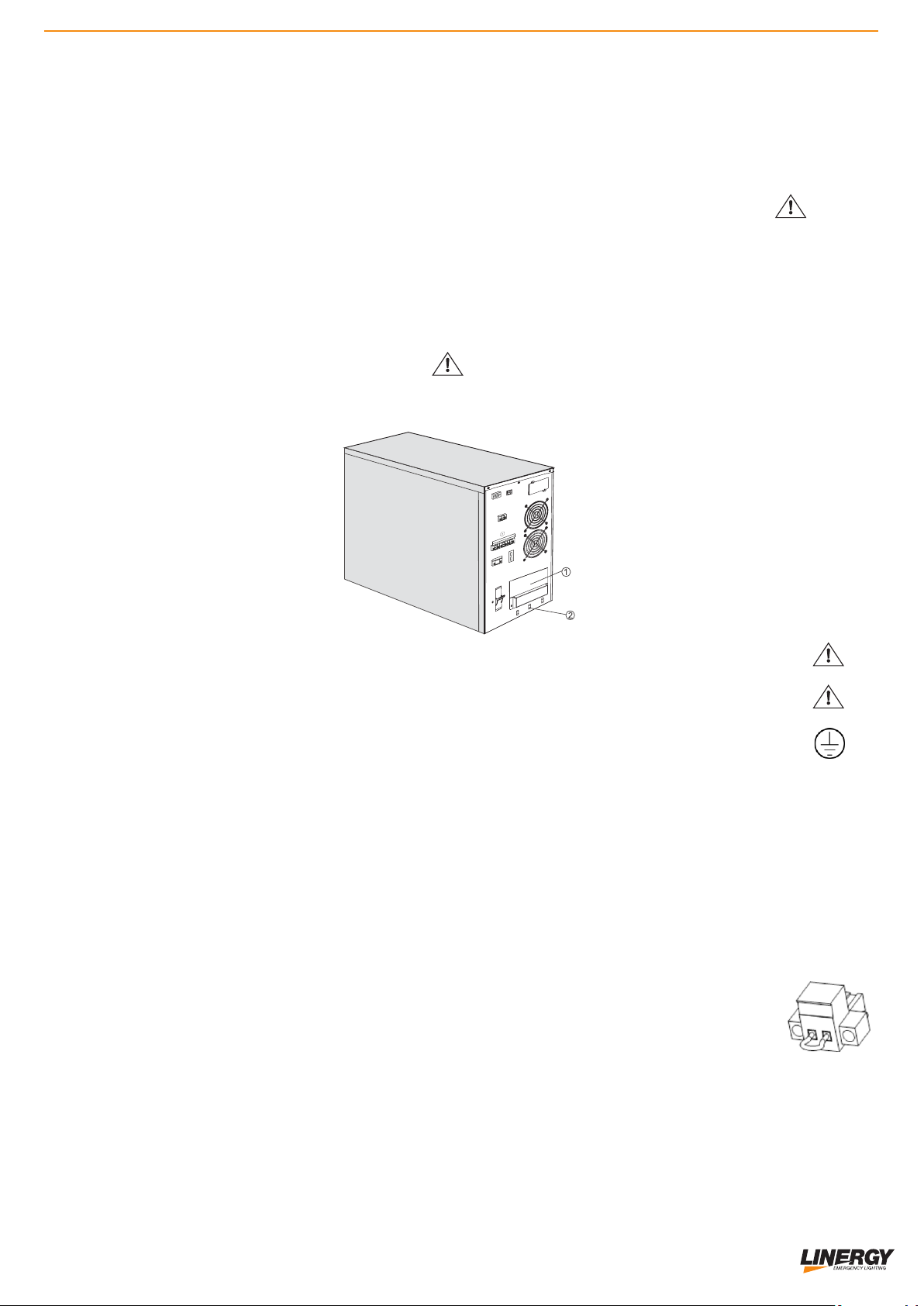
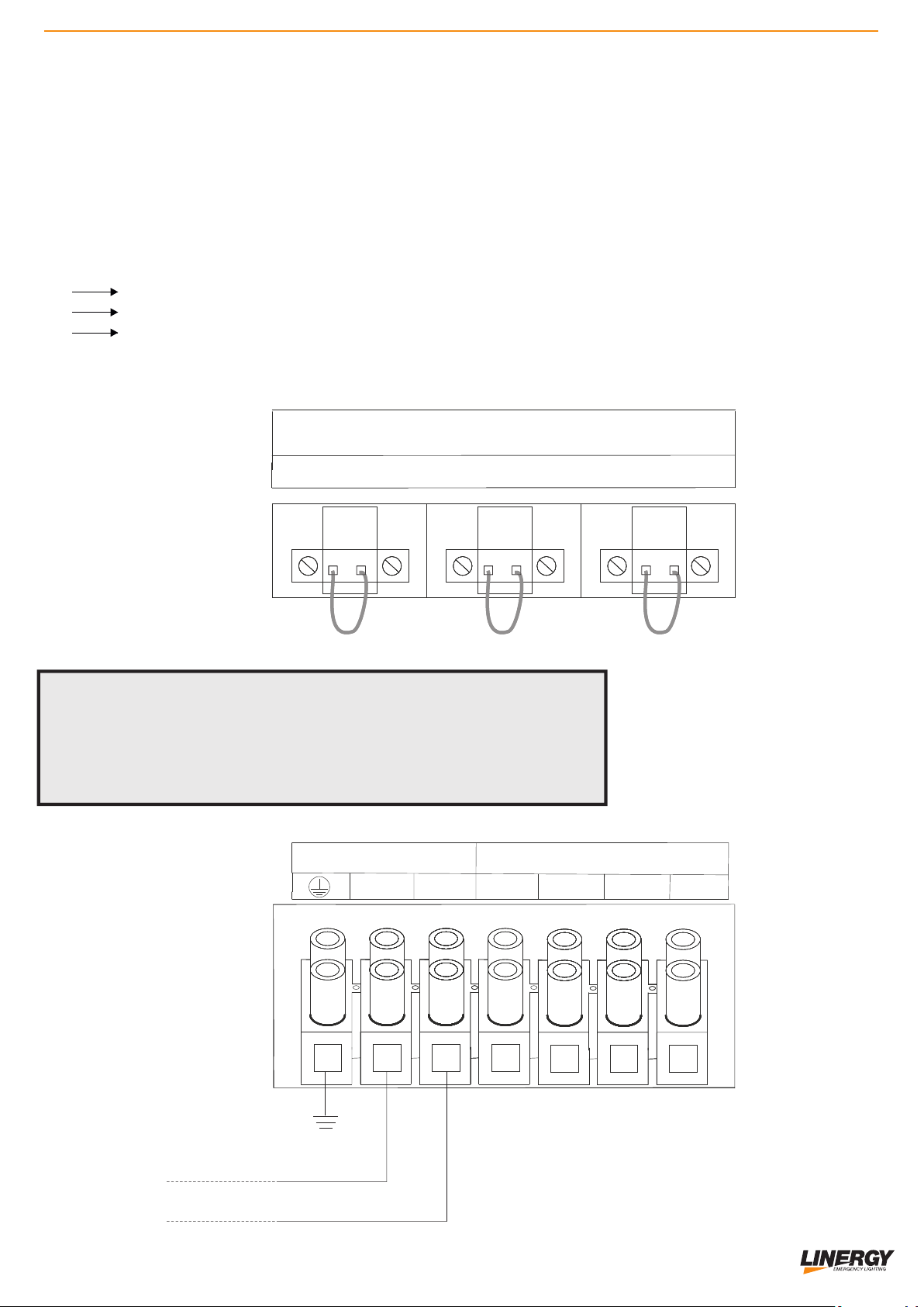
RULES FOR MAKING ELECTRICAL CONNECTIONS
The installation of this equipment must be done by qualified personnel.
The connections must be made in the absence of voltage.
Respect the Phase - Neutral connections.
Always respect the indicated polarity.
The inversion of polarity causes immediate and irreversible damage to the rescuer. Damages due to
polarity inversion are in no case covered by the Linergy S.R.L.
Use tools with insulated handles.
1. Open the terminal block cover located on the UPS rear panel.
The inputs MUST BE PROTECTED BY MAGNETOTHERMAL SWITCH.
Before making the connections, open all the thermal magnetic disconnectors.
2. Make the earth connections to the terminals marked with the conventional symbol.
3. Connect the output line to the terminals marked OUTPUT, respecting the indications of PHASE (L)
and NEUTRAL (N).
4. Firmly secure the cables to the terminals and screw the protection plate back on
The CPS permanently connected to the mains supply are equipped with a single built-in emergency
power off command (EPO = Emergency Power Off) for connection to an external device that allows
the remote shutdown of the load and the supply of energy. of the CPS in any operational state.
Normally requested by the Fire Brigade.
5. Optional: Connect the remote shutdown switch to the contact marked EPO
(Emergency Power OFF).
The EPO contact is Normally Closed. The rescuer turns off when the contact is opened.
The rescuer is supplied with the EPO contact bridged.
6. Connect the battery box with the cable supplied as standard
7. After powering on the AC mains, turn the protection switch (INPUT BREAKER) to ON
At this point it will be possible to turn on the CPS
1
3
OUTPUT CONTROL
K1 K2 K3
NC COM NO +
-
EPO
OUTPUT 12Vdc
EXT BATTERY

5
VENTILATION PROJECT ACCORDING TO EN 50272-2 e CEI EN IEC 62458-2
The amount of air "Q" necessary for the ventilation of a battery compartment, must be calculated
according to the simplified formula:
3
Q = 0.05 x n x Igas x Crt x 10-3 (m / h)
0.05 = v x q x s (v = hydrogen density; q = hydrogen generated; s = safety factor)
n = number of battery elements
Igas = current that produces gas expressed in mA per Ah of delivered capacity, for the floating
recharge current (Ifloat) or for the fast charge current (Iboost).
Crt = nominal battery capacity (Ah for each battery)
The formula for calculating the quantity of air "Q" varies according to the battery technology
The amount of ventilation air flow should preferably be ensured by natural or forced (artificial)
ventilation.
For natural ventilation, the rooms or cabinets of the batteries must have sockets and vents with free
surface calculated with the following formula.
A = 28 x Q
3
Q = amount of ventilation air (m / h)
2
A = free surface of the intake and air vent (cm )
Calculation example: for VRLA batteries with AGM technology (maintenance-free batteries)
UPS: with 40 12V batteries (6 elements of 2V per battery), with a capacity of 100Ah
3
Q = 0.05 x n x Igas x Crt x 10-3 (m / h)
3
0.05 m / Ah
n = number of batteries x N of elements = 240 battery elements (total number of elements)
Igas: 1 (mA / Ah) (for floating voltage)
Crt = 100 (Ah)
3
Q = 0.05 x 240 x 1 x 100 x 10-3 = 1.2m / h
2
A = 28 x 1.2 = 33.6cm
The air "Q" necessary for the ventilation of a battery compartment, must be calculated according
to when reported by law.
A
h
A
h
h ≥ 2 m.
BATTERY
COMPART
MENT
BATTERY
COMPART
MENT
6
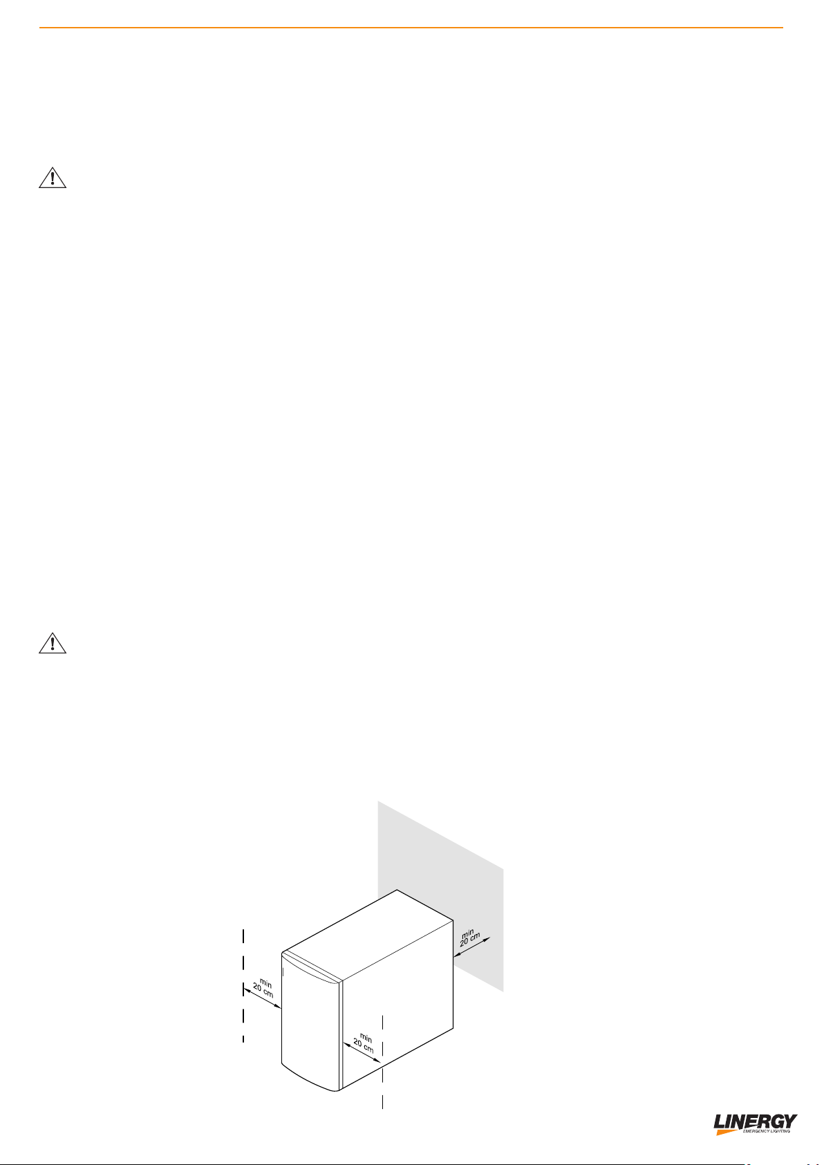
INSTALLATION
Attention: before installing the system, read the safety instructions carefully:
Do not install the central unit (CPS) and the battery box near the water or in humid environments.
Do not install the central unit (CPS) and the battery box in places directly exposed to sunlight or heat
sources.
Do not obstruct the ventilation grills located in the rescuer's housing.
Do not connect devices that could overload the CPS.
Position the cables so that no one can step on or trip over them.
When installing the building's electrical system, it is necessary to provide an appropriate disconnection
device for short circuit protection.
The emergency system must be installed by qualified technical personnel.
The connection to earth is essential before the connection to the terminal of the building's electrical
system.
Do not disconnect the earth cable located on the BACK of the CPS or the terminals of the building's
electrical system as this could cause the cancellation of the protective earth of the CPS and of all the
connected loads.
The CPS output terminal block can be electrically active even if the rescuer is not connected to the
terminal of the building's electrical system, be careful.
To preserve battery life it is necessary to install the unit and the box with the batteries in a
ventilated place where the ambient temperature does not exceed 20-25 °C. A higher temperature
can lead to excessive stress on the accumulator causing irreversible damage.
POSITION
ŸInstall in a dry and ventilated place
ŸDo not block the cooling fans.
ŸDo not expose to atmospheric agents (rain, wind etc.)
ŸDo not install and store the CPS in a way that is not protected from dust, dirt etc.
ŸEnsure ventilation by positioning the appliance at least 20 cm away from walls
ŸDo not cover the front, rear and side ventilation areas.
CHAPTER 2

7
REMOVAL CPS AND THE BATTERY BOX
WARNING: TO AVOID DAMAGE TO PERSONS AND / OR DAMAGE TO THE EQUIPMENT
CAREFULLY FOLLOW THE FOLLOWING INSTRUCTIONS.
SOME OF THE FOLLOWING OPERATIONS NEED THE WORK OF TWO PEOPLE.
§Cut the straps . Remove the packaging material.
§Remove the 2 brackets that secure the CPS to the pallet by unscrewing type A screws
§
The brackets removed previously also serve as slides. Fix the chutes to the pallet using the type A screws
and making sure to align them in correspondence with the wheels..
§ATTENTION :it is recommended to lower the CPS by pushing it from the rear,
with caution and accompanying its descent. Given the weight of the equipment, this operation requires the work .
of two people.
NOTE: It is advisable to keep all parts of the packaging for any future use.
1
3
1
3

8
TEMPERATURE
The life expectancy for lead batteries is reduced by half for each 10 degree increase compared to the
design temperature of 20/25 °C.
Where possible, where an optimal useful cycle is necessary, it is preferable to choose controlled
temperature environments.
Proper ventilation will be provided, so that any potentially explosive mixtures of hydrogen and oxygen
are dispersed before reaching dangerous concentrations.
Ventilation will be designed according to EN 50272-2 "Safety regulations for batteries and
installations".
The EN 50272-2 standard, in section 2, deals with the topic of stationary accumulator batteries,
generally used in UPS applications. The standard describes the safety requirements, including
protections from the dangers generated by electricity, electrolytes and explosive gases. Other
provisions are also provided for the maintenance of the functional safety of batteries and installations.
VRLA (Valve Regulated Lead Acid) batteries, better known as sealed lead batteries with internal gas
recombination, can often be installed without particular safety requirements, since the air flow required
for these batteries is very low.
DO NOT TURN THE BATTERY BOX OVER
CORRECT
DO NOT TURN THE
BATTERY BOX IN ANY
CASE

9
BATTERY MAINTENANCE
ŸThis series of CPS requires minimal maintenance. The batteries used for the standard models are
normal VRLA AGM LEAD batteries with a 10-year life expectancy. These batteries require minimal
precautions. The only request is to keep the CPS regularly under the network in order to charge the
batteries and maximize their life. When the machine is switched on and under mains the CPS keeps
the batteries charged and also offers protection against overcharging or excessive discharging of
the batteries.
ŸThe CPS should be fed every 4 or 6 months if not used for a long time.
ŸIn countries with high temperatures, batteries should be recharged every 2 months. The standard
charging time is at least 12 hours.
ŸUnder normal conditions, the life of the batteries is approximately 10 years. If the batteries are not
found in good conditions, they must be replaced as soon as possible.
Batteries must be replaced by qualified personnel.
If necessary, replace the batteries with Linergy batteries of the same type.
Do not replace batteries individually. All batteries should be replaced at the same time following the
instructions of Linergy Srl.
Normally, batteries should be charged and discharged every 4-6 months. Charging should be done
after the CPS shuts down completely in battery mode, the standard full charge time is 12 hours.
Do not place the battery pack in a heat source, they could explode.
Do not open or cut the batteries in any way, the electrolyte is highly poisonous and harmful to the eyes
and skin.
Do not connect the positive and negative pole of the batteries, it could cause an electric shock or a fire.
Make sure there is no voltage before touching the batteries. The battery circuit is not isolated from the
input circuit. Dangerous voltage may occur between the battery poles and the earth.
10
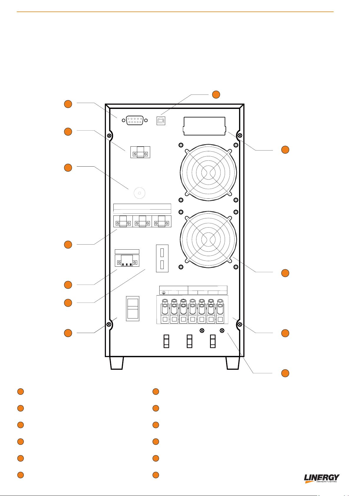
1 1 1
1
INPUT BATTERY BOX
OUTPUT 12V
OUTPUT DRY CONTACT
OUTPUT CONTROL
EPO
RS 232
2
3
4
5
6
12
8
47
ON
OFF
1
3
1
3
Input Breaker
OUTPUT CONTROL
K1 K2 K3
NC COM NO +
-
N
LL3 N
Input Ouput
L1 L2
5
6
4
3
2
1
11
10
9
7
GROUND
INTELLIGENT SLOT
INPUT OUTPUT 230Vac
FAN
USB
INPUT SWITCH
8
9
10
11
12
EPO
OUTPUT 12Vdc
EXT BATTERY
REAR VIEW CPS
11
ELECTRICAL CONNECTIONS DIAGRAM
N
LL3 N
Input Ouput
L1 L2
OUTPUT CONTROL
K1 K2 K3
K closed = Not Maintained (NM) enabled relative output L
n n
K open = Maintained (M) enabled relative output L
n n
230 V~
The CPS is equipped with 3 single-phase outputs (L1-N; L2-N; L3-N) which can be managed
individually in Not Maintained (NM) or Maintained (M) through the Output control (K1; K2; K3) . By
jumpering the relevant terminal it is possible to configure the Not Maintained (NM), by opening the
circuit, we have the circuit Maintained (M).
Each output Ln is associated with its own control terminal Kn:
L1 K1
L2 K2
L3 K3
OUTPUT CONTROL
K1 K2 K3
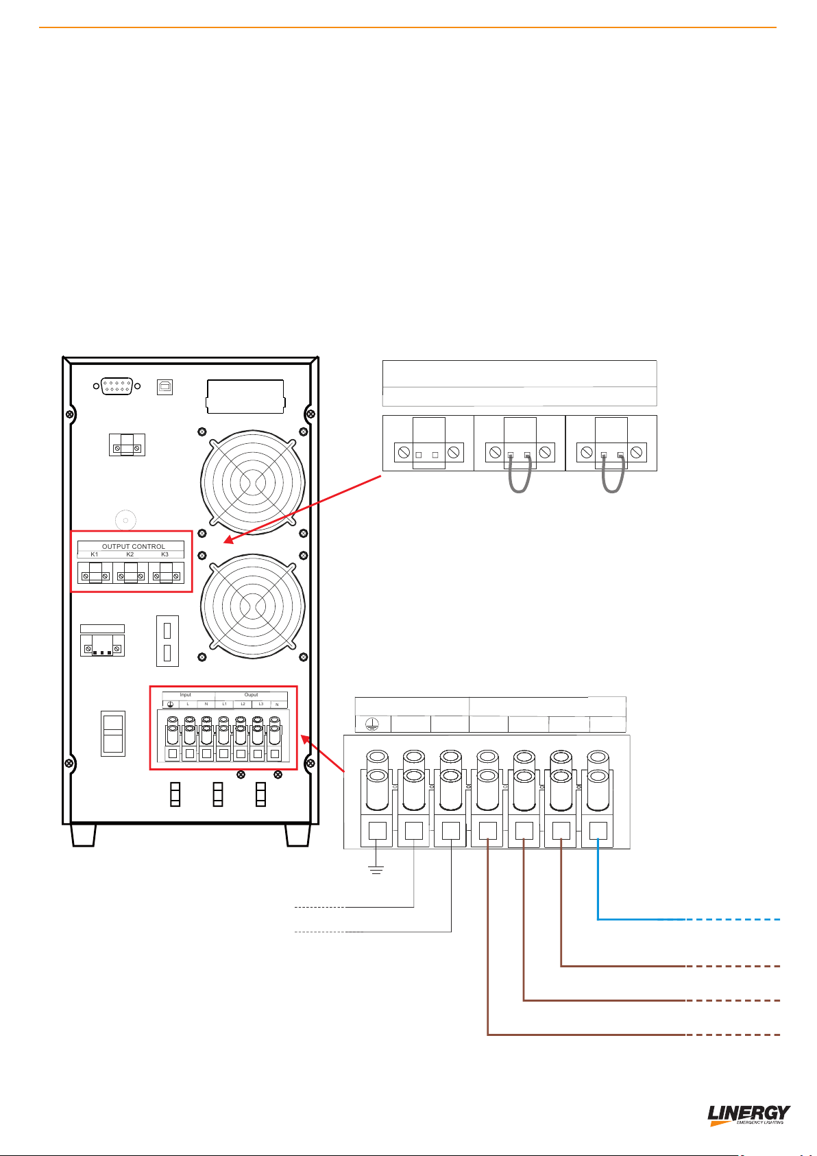
12
N
LL3 N
Input Ouput
L1 L2
OUTPUT CONTROL
K1 K2 K3
CONFIGURATION ‘’Ln’’
Jumper K1 open Circuit 1 ‘’M’’
Jumper K2 closed Circuit 2 ‘’NM’’
Jumper K3 closed Circuit 3 ‘’NM’’
230 V~
ON
OFF
Input Breaker
OUTPUT CONTROL
K1 K2 K3
NC COM NO +
-
N
LL3 N
Input Ouput
L1 L2
EPO
OUTPUT 12Vdc
EXT BATTERY
Example of configuration of the output circuits:
K1 jumper open the output circuit L1 is enabled in Maintained (M)
K2 jumper closed the output circuit L2 is enabled in Not Maintained (NM)
K3 jumper closed the output circuit L3 is enabled in Not Maintained (NM)
13
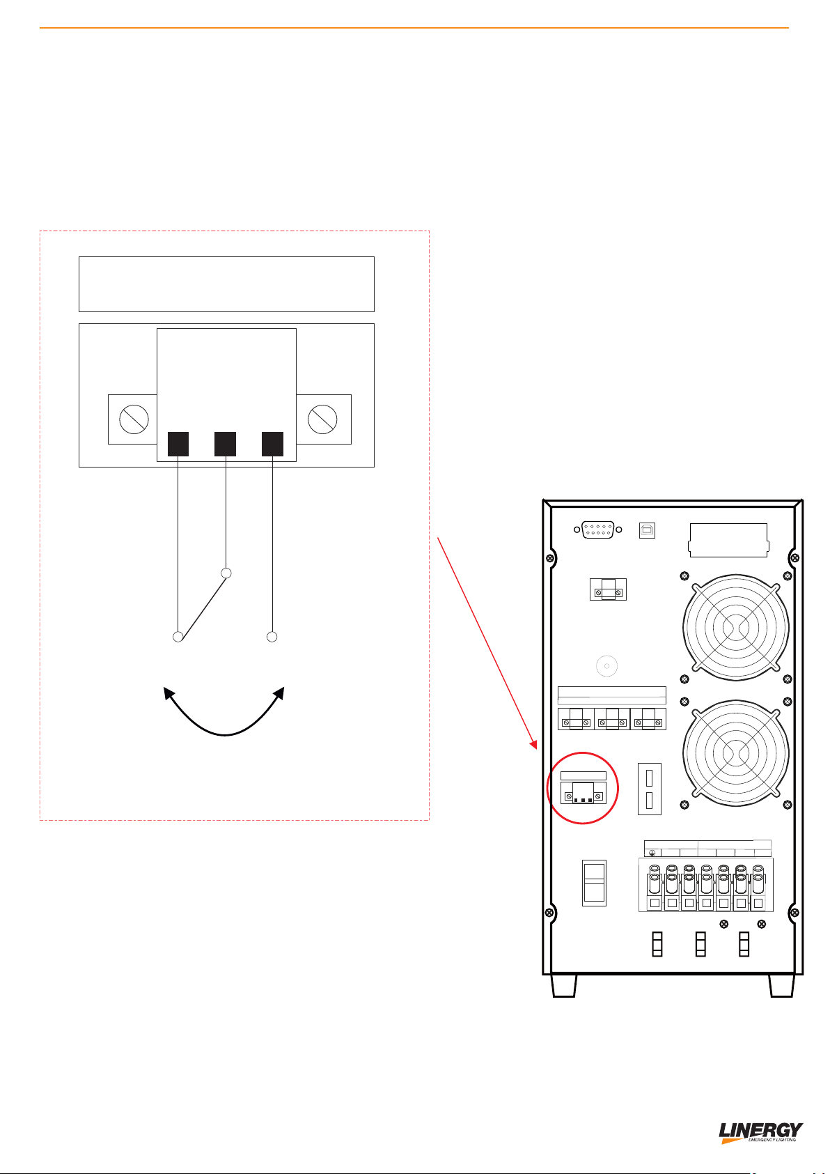
RELE’ NC/NO
The system is equipped as standard with an output for remote signaling dry contacts.
It is activated in the event of black out (230Vac), it signals the general emergency status.
ON
OFF
Input Breaker
OUTPUT CONTROL
K1 K2 K3
NC COM NO +
-
N
LL3 N
Input Ouput
L1 L2
EPO
OUTPUT 12Vdc
EXT BATTERY
NC COM NO
OPEN=OK
CLOSED=EMERGENCY
OPEN=EMERGENCY
CLOSED=OK

14
CONNECT THE BATTERY BOX
The battery BOX is supplied with the battery circuit already connected inside.
To connect the Battery BOX to the inverter, use the RED and BLACK CABLE with connector (supplied
in the KIT together with the fuses) connecting them to the EXT BATTERY terminal block respecting the
polarity as shown in the diagram
The inversion of polarity causes immediate and irreversible damage to the CPS.
Damages due to polarity inversion are in no case covered by the Linergy S.R.L.
Connecting the battery box to the CPS, close the circuit by inserting the fuses provided in the fuse
holder inside.
ON
OFF
Input Breaker
OUTPUT CONTROL
K1 K2 K3
NC COM NO +
-
N
LL3 N
Input Ouput
L1 L2
EPO
OUTPUT 12Vdc
EXT BATTERY

15
EPO CLAMP
EPO deactivated (Emergency enabled) EPO activated (Emergency disabled)
INT
11
12
EPO deactivated (Emergency enabled)
with display on external module*
INT
11
12
EPO deactivated (Emergency disabled)
with display on external module*
EPO CLAMP WITH OPTIONAL MODULE cod.SCBMOD
EMERGENCY POWER OFF (EPO)
The emergency stop function (EPO = Emergency Power-Off) is used for immediate remote shutdown
of the system and connected users. For this purpose it is necessary to remove the jumper from the
emergency stop plug (on the back of the system) and connect an external emergency stop switch.
Cross-section of the connection cable = 0.5 - 2.5mm2 (AWG 13 - 20)
Recommended section of the connection cable = 1.5mm2 (AWG 15)

16
SWITCHING ON THE CPS with the mains present. ( Line mode/
AC mode).
1) After making sure that the connections have been made correctly first place
the protection switch in the ON position. (fig.1)
2) To activate the CPS in operating mode, keep the keys pressed
simultaneously for 0.5 seconds.
3) When the CPS is turned on, the control unit starts a self-diagnosis, which
checks the battery charge and turns on the battery level scale indicating the
state of charge. After a few seconds, the machine runs in operating mode.
4) In the event that there is an interruption in the input network (signaled by an
audible warning via a beep), the CPS will switch to battery mode without
interrupting the direct supply to the Maintained (M) output load while the Not
Miantained (NM) output will be powered.
Attention it is recommended to turn off all the loads connected to the CPS before turning it off
both in battery mode and in mains present mode.
SWITCHING OFF THE CPS with the mains present.
1) Press simultaneously for more than 0.5 seconds to turn off the
INVERTER in operation.
2) The inverter shutdown and the system goes in standby mode.
3) To switch off the machine completely, disconnect the main power supply, after
a few seconds the display and the machine switch off completely.
(INPUT BREAKER)
OUTPUT CONTROL
K1 K2 K3
NC COM NO +
-
EPO
OUTPUT 12Vdc
EXT BATTERY
fig.1
Other manuals for SPY CENTER BASIC SCB050 Series
1
This manual suits for next models
1
Table of contents
Other Linergy Power Supply manuals


