Ericsson MINI-LINK E Parts list manual

MINI-LINK E and E Micro
Technical Description
MINI-LINK™


MINI-LINKEandEMicro
Technical Description
E

Copyright
© Ericsson Microwave Systems AB. All rights reserved. No parts of this
publication may be reproduced, stored in a retrieval system, or transmitted in
any form or by any means, electronic, mechanical, photocopying, recording or
otherwise, without prior permission of the publisher.
Disclaimer
The contents of this document are subject to revision without notice due to
continued progress in methodology, design, and manufacturing. Ericsson shall
have no liability for any error or damage of any kind resulting from the use
of this document.
If there is any conflict between this document and compliance statements, the
latter will supersede this document
AE/LZT 110 2012 R8C 2002-03-04

MINI-LINKEandEMicro
Contents
1 Introduction 1
1.1 General 1
1.2 Applications 2
1.3 Main Features 5
1.4 Related Documents 6
2 Product Program 7
2.1 Introduction 7
2.2 MINI-LINK E 8
2.3 MINI-LINK E Micro 18
2.4 Network Management 20
3MINI-LINKE 23
3.1 General 23
3.2 Radio Units 23
3.3 RAU1 (7-E and 8-E) 25
3.4 RAU1 (15-E, 18-E, 23-E, 26-E and 38-E) 30
3.5 RAU2 35
3.6 Access Module 40
3.7 AMM – Access Module Magazine 41
3.8 MMU – Modem Unit 43
3.9 SMU – Switch Multiplexer Unit 53
3.10 SAU – Service Access Unit 63
3.11 ETU – Ethernet Interface Unit 69
3.12 Traffic Routing 74
3.13 Upgrading 77
4 MINI-LINK E Micro 79
4.1 General 79
4.2 RTU – Radio Unit 79
4.3 Block Diagram 82
4.4 Modem Board 82
4.5 Microwave Unit 86
4.6 Filter Unit 88
AE/LZT 110 2012 R8C 2002-03-04

MINI-LINKEandEMicro
5 Antennas 89
5.1 Antenna Description 89
5.2 Antenna Installation 90
6 Management System 93
6.1 Operation and Maintenance Facilities 93
6.2 MSM – MINI-LINK Service Manager 110
6.3 MINI-LINK Netman 111
7 Accessories 113
7.1 RCB – Radio Connection Box 113
7.2 MXU – MINI-LINK Cross-connect Unit 115
7.3 DDU – DC Distribution Unit 120
7.4 PSU – AC/DC Power Supply Unit 122
7.5 Terminal Server 124
8 Technical Data 125
8.1 System Parameters 125
8.2 Antenna Data 135
8.3 Environmental Requirements 139
8.4 Power Supply 140
8.5 Cables 143
8.6 Interfaces 147
8.7 ETU Data 152
8.8 MXU Data 152
8.9 Fan Unit Data 154
8.10 DDU Data 154
8.11 PSU Data 154
8.12 Mechanical Data 156
8.13 Management System Data 171
Glossary 175
Index 179
AE/LZT 110 2012 R8C 2002-03-04

MINI-LINKEandEMicro
1 Introduction
1.1 General
MINI-LINK E and MINI-LINK E Micro are product families for medium capacity
point-to-point microwave transmission. The purpose of this description is
to support the reader with detailed information on included products with
accessories, from technical and functional points of view.
For ordering information, please refer to the latest revision of the MINI-LINK E
and E Micro Product Catalog (AE/LZT 110 2011).
You may also contact your Ericsson representative or the business manager for
your country at:
Ericsson Microwave Systems AB
Transmission & Transport Networks
SE-431 84 Mölndal, SWEDEN
Telephone: +46 31 747 00 00
Fax: +4631277225
1.1.1 Revision Information
This revision of the MINI-LINK E and E Micro Technical Description includes the
introduction of the following:
• Ethernet Interface Unit (ETU)
• RAU2 for 28 GHz
• 1.8 m compact antennas
• Terminal server
Most of the technical description of MINI-LINK Netman in Section 6.3 on page
111 has been transferred to Netman Technical Description (AE/LZT 110 5048).
1
AE/LZT 110 2012 R8C 2002-03-04

MINI-LINKEandEMicro
1.2 Applications
MINI-LINK is a member of Ericsson’s large and extensive product portfolio for
telecommunications. The combined expertise of Ericsson, covering switching,
cellular technology, radio and networking, provides excellent turnkey project
management. MINI-LINK integrates fully with existing telecom networks, adding
new levels of flexibility. It has proved to be a reliable communication medium, a
highly competitive alternative to copper and fiber cable.
MINI-LINK E and E Micro provides point-to-point microwave transmission from
2 up to 34+2 (17x2) Mbit/s, operating within the 7 to 38 GHz frequency bands.
They are briefly described as follows:
•MINI-LINK E comprises an indoor access module and an outdoor radio
unit with antenna. It offers flexibility and capacity at small sites as well as
large multi-terminal sites. Terminals can be configured for different network
types: star, tree or ring. For protection, they can be configured either as a
1+1 system or as a ring structure.
•MINI-LINK E Micro is a compact all-outdoor terminal providing minimal
total site cost, typically used at end sites together with other all-outdoor
equipment.
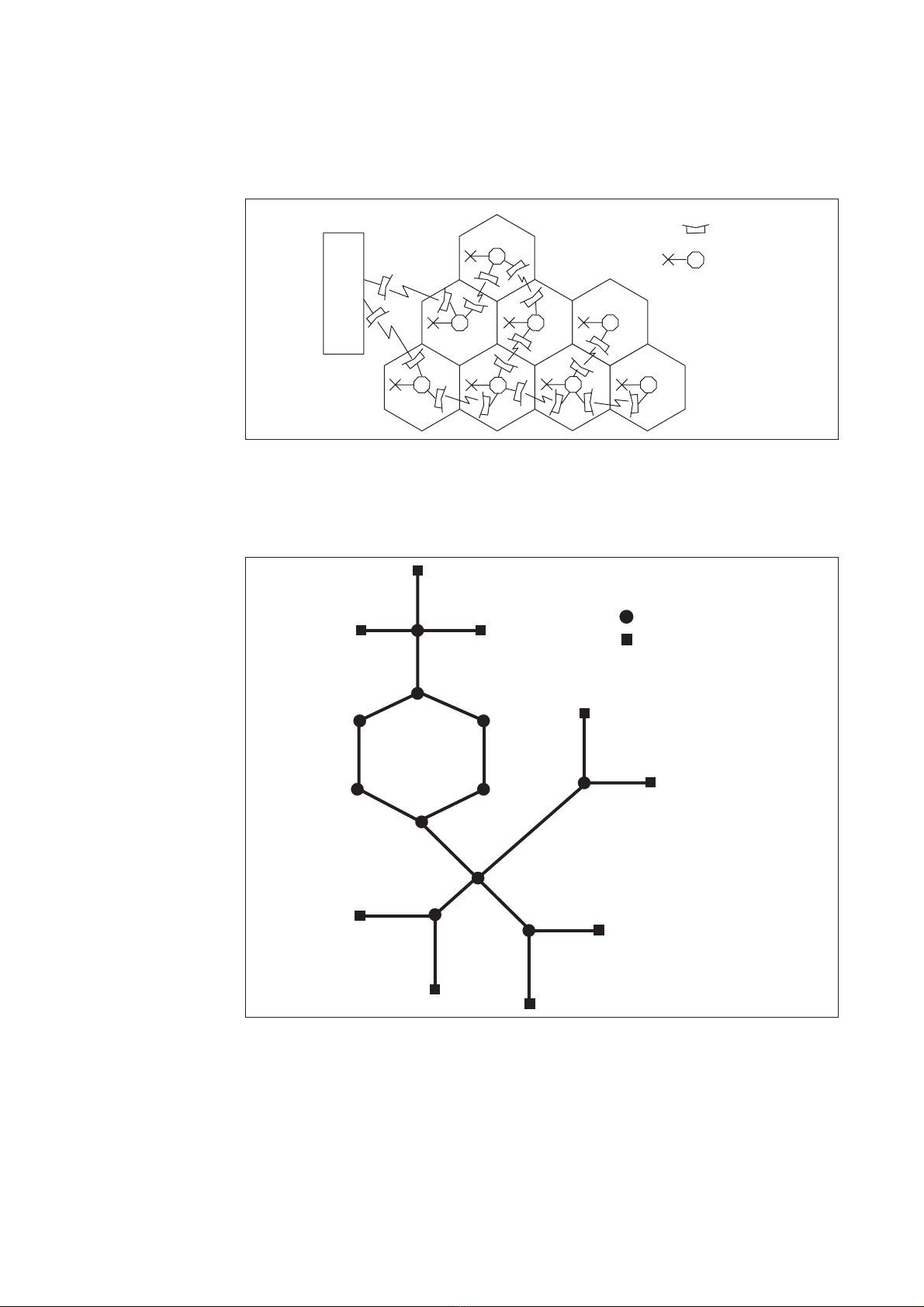
A mobile transmission network is by far the most common application of
MINI-LINK E and E Micro, where they are deployed in the Low Capacity Radio
Access Network (LRAN).
5558
Switch site
Transmission
hub site
Core Network
High Capacity Radio
Access Network
(HRAN)
Low Capacity Radio
Access Network
(LRAN)
MSC/
MG
MSC/
MG
BSC/
RNC
HUB
HUB
HUB
MSC - Mobile Switching Center
MG - Media Gateway
BSC - Base Station Controller
RNC - Radio Node Controller
Figure 1 A mobile transmission network
2AE/LZT 110 2012 R8C 2002-03-04

MINI-LINKEandEMicro
Base station
MSC
BSC
MINI-LINK
3503
Figure 2 Example of a mobile network, where MINI-LINK products connect
radio base stations to switching centers
The figure below shows an example of how MINI-LINK E and E Micro can be
used in different network topologies.
Ring
Star
Tree
MINI-LINK E
MINI-LINK E Micro
3500
Figure 3 Example of network topologies
3
AE/LZT 110 2012 R8C 2002-03-04

MINI-LINKEandEMicro
The following figures show applications in a private and fixed network.
PBX
PBX
PBX
Public
network
3501
Figure 4 Example of a private network, where MINI-LINK products connect
major sites
RSS
RSM
AXE
RSS
RSS
3502
Figure 5 Example of a fixed network using AXE systems, where remote
subscriber access units are connected to the network with MINI-LINK products
4AE/LZT 110 2012 R8C 2002-03-04

MINI-LINKEandEMicro
1.3 Main Features
Technical features
• Extremely compact and integrated design
• The radio and antenna form an integrated outdoor part
• High system gain and spectrum utilization with an advanced modulation
process and coding
• 2 to 17x2 (34+2) Mbit/s traffic capacity
• Software tool for easy installation
• Advanced element manager
• Standardized interfaces
• Low weight and power consumption
Reliability
• High Mean Time Between Failure (MTBF)
• Progress with backward compatibility
• Part of the Ericsson system portfolio
• 30 years’ experience of microwave transmission
• World’s largest production of microwave transmission systems
• MINI-LINK equipment can cope with extreme environments
Services
• Ericsson turnkey capability
• Customer training programs worldwide
• Total field maintenance services
• Ericsson local presence in more than 140 countries
5
AE/LZT 110 2012 R8C 2002-03-04

MINI-LINKEandEMicro
1.4 Related Documents
This section gives an overview of some MINI-LINK E and E Micro related
documents. The documents can be ordered separately and can also be
downloaded from the Ericsson Intranet and customer Extranet portals.
MINI-LINK E and E Micro Product Catalog (AE/LZT 110 2011)
The product catalog is intended to be an aid when compiling an order or just
to give a more detailed overview of the products in the MINI-LINK E and E
Micro product families.
Netman Technical Description (AE/LZT 110 5048)
The document describes the technical features of the element management
system Netman.
MINI-LINK E and E Micro Planning and Engineering Manual (EN/LZT 110
2013)
The manual is used for planning and engineering of a MINI-LINK E and E Micro
network.
6AE/LZT 110 2012 R8C 2002-03-04

MINI-LINKEandEMicro
2 Product Program
2.1 Introduction
A terminal is one side of a microwave radio link hop, between two geographical
locations. The networks of today contain both single terminal sites and more
complex multi-terminal sites. MINI-LINK E and E Micro feature these types of
terminal configurations, further described in this chapter.
Antenna
Radio
unit
MINI-LINK E Micro
Antenna
Radio
unit
Access
module
To operator
equipment
MINI-LINK E
To all-outdoor
operator equipment
5500
Figure 6 Two examples of terminal configuration
7
AE/LZT 110 2012 R8C 2002-03-04

MINI-LINKEandEMicro
2.2 MINI-LINK E
Several MINI-LINK E terminals can be integrated into one common access
module. This enables extremely compact network sites as well as efficient
sharing of resources between different terminals, such as multiplexers, service
channel interfaces and support systems.
Traffic routing and re-routing within a network site can be performed with a
minimum of external cables. Traffic routing is software configured during station
setup.
Terminals can be configured for unprotected (1+0), protected (1+1) terminals
or ring protection.
Each terminal provides traffic capacity for up to 17x2 (34+2) Mbit/s.
3522
Figure 7 A MINI-LINK E multi-terminal site
8AE/LZT 110 2012 R8C 2002-03-04

MINI-LINKEandEMicro
2.2.1 System Components
Antenna
Radio
unit
Access
module
To operator
equipment
3520
Figure 8 The main parts of a MINI-LINK E terminal
A MINI-LINK E terminal consists of an outdoor and indoor part. There are also
a number of well-adapted accessories, both hardware and software.
Outdoor Part
The outdoor part is fully independent of traffic capacity and supplied for various
frequency bands.
It consists of an antenna module, a Radio Unit (RAU) and associated
installation hardware. The antenna and the radio unit are either integrated or
installed separately. For protected systems (1+1), two radio units and one or
two antennas are used.
Indoor Part
The indoor part, the access module, is fully independent of frequency band
and supplied in different versions for various traffic capacities and system
configurations. It can support up to four radios.
It consists of a Modem Unit (MMU) and an optional Switch Multiplexer Unit
(SMU), as well as an optional Service Access Unit (SAU), all housed in one
common Access Module Magazine (AMM). For protected systems, two MMUs
and one SMU are used.
The indoor part is connected to the outdoor part with a single coaxial cable
(the radio cable).
For Ethernet traffic the optional ETU can be used, see Section 3.11 on page 69.
For ring protection the optional MINI-LINK Cross-connect Unit (MXU) can be
used, see Section 7.2 on page 115.
9
AE/LZT 110 2012 R8C 2002-03-04

MINI-LINKEandEMicro
Antenna
Radio
unit
Access module
(SAU)
MMU
MMU
SMU
SMU
MMU
MMU
3507
Figure 9 A multi-terminal site
2.2.2 Outdoor Installation
The radio unit and the antenna are easily installed on a wide range of support
structures.
The radio unit is fitted directly to the antenna as standard, integrated installation.
The radio unit and the antenna can also be fitted separately and connected by
a flexible waveguide.
In both cases, the antenna is easily aligned and the radio unit can be
disconnected and replaced without affecting the antenna alignment.
3519
Figure 10 The radio unit fitted directly to a 0.2 m compact antenna and a
0.6 m compact antenna respectively
10 AE/LZT 110 2012 R8C 2002-03-04

MINI-LINKEandEMicro
3508
Figure 11 The radio unit and a 0.6 m compact antenna fitted separately
2.2.3 Indoor Installation
The indoor parts are fitted in 19" racks, in ETSI and BYB cabinets or directly
on the wall/desk. An access module consists of an Access Module Magazine
(AMM) and a set of different plug-in units. The following AMMs for different
applications are available as standard:
• AMM 1U for end terminals
• AMM 2U-3 for single or dual terminal sites, containing up to four plug-in units
• AMM 4U for more complex, multi-terminal sites, containing up to seven
plug-in units
The indoor part can be upgraded or reconfigured with plug-in units, providing
site flexibility.
The interconnection between the outdoor part (radio unit and antenna) and
the indoor part is a single coaxial cable carrying full duplex traffic, DC supply
voltage, service traffic as well as operation and maintenance data.
11
AE/LZT 110 2012 R8C 2002-03-04

MINI-LINKEandEMicro
3514
Figure 12 The AMM 2U-3 for a maximum of four units
1234
Figure 13 The AMM 4U for a maximum of seven units
12 AE/LZT 110 2012 R8C 2002-03-04

MINI-LINKEandEMicro
2.2.4 Configurations
2.2.4.1 Unprotected Terminal (1+0)
As a minimum a 1+0 terminal consists of:
•RAU
• Antenna
•AMM1U
• MMU
• Coaxial cable for interconnection
For traffic capacities 8x2, 17x2 and 4x8+2, an SMU is required. An SAU can be
added to the AMM to provide additional alarm and control interfaces, service
channels and other customer specific applications.
MMU
AMM 1U
2x2, 4x2,
8, 2x8 or
34+2 Mbit/s 3510
Figure 14 1+0 configuration. The MMU can be installed in an AMM 1U
(AMM 2U-3 if SAU is required).
4492
Figure 15 1+0 configuration for 8x2, 4x8+2 and 17x2 Mbit/s capacities
13
AE/LZT 110 2012 R8C 2002-03-04

MINI-LINKEandEMicro
2.2.4.2 Protected Terminal (1+1)
As a minimum, a 1+1 terminal consists of:
• Two RAUs
• Two antennas or one antenna with a power splitter
• One AMM 2U-3 (or AMM 4U) with two MMUs and one SMU
• Two coaxial cables for interconnection
4493
Figure 16 1+1 configuration requires an AMM 2U-3 (AMM 4U can be used
as an alternative)
An SAU can also be added to the AMM to provide additional alarm and control
interfaces, service channels and other customer specific applications.
The radio units can be equipped with individual antennas or connected to a
common antenna. In the case of one common antenna, the two radio units
are connected by waveguides to a power splitter, fitted on a single-polarized
antenna.
Automatic switching can be in hot standby or in working standby (frequency
diversity). Receiver switching in space diversity systems is hitless.
In hot standby mode, one transmitter is working while the other one is in
standby (that is, not transmitting but ready to transmit if the active transmitter
malfunctions). Both radio units are receiving signals. The MMU selects the
best signal according to an alarm priority list, connects it first to the SMU for
demultiplexing and then to external equipment. See Section 3.9.2.6 on page 58
for further information about switching.
In working standby mode, both radio paths are active in parallel using different
frequencies.
The 1+1 configuration should be considered for important and/or heavy traffic
requiring high availability, but also if there are severe reflections and/or harsh
atmospheric conditions.
14 AE/LZT 110 2012 R8C 2002-03-04
This manual suits for next models
1
Table of contents