manuals.online logo
Brands
  1. Home
  2. •
  3. Brands
  4. •
  5. Mighty Module
  6. •
  7. Transmitter
  8. •
  9. Mighty Module MM4431 User manual

Mighty Module MM4431 User manual

DESCRIPTION
The MM4431 raises its input to a power and
provides an output voltage or current pro-
portionaltothatpowerfunction(Y=Xm). The
exponent M can be a value between 0.2 and
5. This range covers the most common
requirementsformeasuringdifferentialpres-
sure in flow applications such as encoun-
tered in orifice plate or pitot tubes.
TherangeofMalsoincludestherangesused
toprovideflowdatafromParshallflumesand
V-notch weirs. In a Parshall flume, the flow
isrelatedtotheheightoftheliquidlevelbythe
3/2 power of the height. In a V-notch weir,
flow is related by the 5/2 power to the liquid
height.
The MM4431 uses a complex integrated
circuit to find the exponent of the input
signal. Theexponentischosenbythechoice
of two precision resistors and allows the unit
to be factory-scaled for a wide selection of
exponent values.
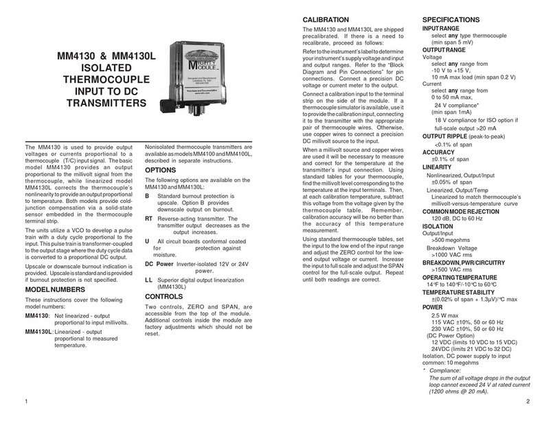
The following tables show the input/output
relationship for square root, using 4-20 mA
inputs and outputs.
MM4431
DC INPUT
POWER FUNCTION
EXPONENTIATOR
TRANSMITTER Y=Xm
OPTIONS
The following options are available of the
MM4431:
U All circuit boards conformal coated for
protection against moisture.
DCPower Inverter-isolated12Vor24VDC
power.
CONTROLS
Twocontrols,ZEROandSPAN,areavailable
at the top of the module. The exponent, M,
is not adjustable
SPECIFICATIONS
Input Impedance
Voltage
100K
Current
1.25V drop std at 20 mA,
others available
Output Limits
Voltage
-10 to +15 V, 10 mA
Current
50 mA, 24V compliance
Accuracy
0.4 £M £4
±0.15% of span
Isolation
Input/Output
greater than 500 megohms
1000 VAC rms
Temperature Stability
±0.04% of span per ° C
Common Mode Rejection
100 dB, DC to 60 Hz
Temperature, Operating
0 ° C to 60 ° C
32 ° F to 140 ° F
POWER (2.5 MAX)
115 VAC ±10%, 50 or 60 Hz
230 VAC ±10%, 50 or 60 Hz
(DC Power Option)
12 VDC (limits 10 VDC to 15 VDC)
24VDC (limits 21 VDC to 32 VDC)
CALIBRATION
The MM4431 is shipped precalibrated. If
there is a need to recalibrate, proceed as
follows:
Refer to the instrument's label to determine
your instrument's supply voltage, exponent
(M), and input and output ranges. Refer to
the"BlockDiagramandPinConnections"for
pin connections.
Connect a precision DC voltage or current
sourceto theinput. Connect aprecision DC
voltage or current meter to the output.
Settheinputtothelowendoftheinputrange
and adjust the ZERO control for the low-end
outputvoltage orcurrent. Increasethe input
to full scale and adjust the SPAN control for
thefull-scaleoutput. Repeat untilboth read-
ings are correct.
MOUNTING
Themoduleisdesignedtoplugintoastandard
8-pin relay socket.
MP008isamoldedplasticsocketsuitablefor
mounting on a flat surface or in a 2 3/4 inch
widePVCsnaptrackTRK48.SocketDMP008
is a 8-pin DIN rail mounted socket.
Use CLP1 hold-down clip if needed for
vibration environment (MP008 only). A
Killark HK Series explosion-proof housing
withdomeand8-pinsocketisavailableHKB-
HK2D-8.
WARRANTY
The Mighty Module Series of products carry
a limited warranty of 10 + 5 years. In the
event of a failure due to defective material
or workmanship, during the 10 year period,
the unit will be repaired or replaced at no
charge. For a period of 5 years after the
initial 10 year warranty, the unit will be
repaired, if possible, for a cost of 10% of
the original purchase price.
Relays are not covered by the warranty.
1 2
I OUT VERSUS I IN FORM=1.5 I OUT VERSUS I IN FORM=2.5
I IN I OUT I IN I OUT
4.000 4.000 4.000 4.000
5.000 4.250 5.000 4.016
6.000 4.707 6.000 4.088
7.000 5.299 7.000 4.244
8.000 6.000 8.000 4.500
9.000 6.795 9.000 4.873
10.000 7.674 10.000 5.378
11.000 8.630 11.000 6.026
12.000 9.657 12.000 6.828
13.000 10.750 13.000 7.797
14.000 11.906 14.000 8.941
15.000 13.121 15.000 10.270
16.000 14.392 16.000 11.794
17.000 15.718 17.000 13.521
18.000 17.096 18.000 15.459
19.000 18.524 19.000 17.616
20.000 20.000 20.000 20.000
I OUT VERSUS I IN FORM=0.5 I OUT VERSUS I IN FORM=M2
I IN I OUT I IN I OUT
4.000 4.000 4.000 4.000
5.000 8.000 5.000 4.063
6.000 9.657 6.000 4.250
7.000 10.928 7.000 4.563
8.000 12.000 8.000 5.000
9.000 12.944 9.000 5.563
10.000 13.798 10.000 6.250
11.000 14.583 11.000 7.063
12.000 15.314 12.000 8.000
13.000 16.000 13.000 9.063
14.000 16.649 14.000 10.250
15.000 17.266 15.000 11.563
16.000 17.856 16.000 13.000
17.000 18.422 17.000 14.563
18.000 18.967 18.000 16.250
19.000 19.492 19.000 18.063
20.000 20.000 20.000 20.000
Specifications are subject to change withoout notice. © 2008 Wilkerson Instrument Co., Inc. DWG#101065B 06/08
SEE INSTRUMENT LABEL
FOR POWER INPUT
CASE DIMENSIONS INCHES [mm]
3 4

Other Mighty Module Transmitter manuals

Mighty Module MM4130 User manual

Mighty Module

Mighty Module MM4130 User manual

Mighty Module MM4001 User manual

Mighty Module

Mighty Module MM4001 User manual

Mighty Module MM4010 User manual

Mighty Module

Mighty Module MM4010 User manual

Mighty Module MM4300A User manual

Mighty Module

Mighty Module MM4300A User manual

Mighty Module MM7010 User manual

Mighty Module

Mighty Module MM7010 User manual

Mighty Module MM6010 User manual

Mighty Module

Mighty Module MM6010 User manual

Mighty Module MM4410 User manual

Mighty Module

Mighty Module MM4410 User manual

Popular Transmitter manuals by other brands

ClearSounds QLINK user manual

ClearSounds

ClearSounds QLINK user manual

Intra Automation ITA-T1S technical information

Intra Automation

Intra Automation ITA-T1S technical information

Savant PAV-VIMAP8S Quick reference guide

Savant

Savant PAV-VIMAP8S Quick reference guide

NIVELCO NIPRESS D 3 Series user manual

NIVELCO

NIVELCO NIPRESS D 3 Series user manual

Linear LMT-1 instruction manual

Linear

Linear LMT-1 instruction manual

Kenco KT Series Interface manual

Kenco

Kenco KT Series Interface manual

VicTsing BH501 user manual

VicTsing

VicTsing BH501 user manual

Motorola SG2-DRT-3X Installation sheet

Motorola

Motorola SG2-DRT-3X Installation sheet

Mercoid 3200 Series Installation and operating instructions

Mercoid

Mercoid 3200 Series Installation and operating instructions

Transmitter Solutions Firefly 3 manual

Transmitter Solutions

Transmitter Solutions Firefly 3 manual

Baumer FlexTop 2202 operating instructions

Baumer

Baumer FlexTop 2202 operating instructions

PTN TPVG201 user manual

PTN

PTN TPVG201 user manual

Nuova Fima ST Series user guide

Nuova Fima

Nuova Fima ST Series user guide

NIVELCO EchoTREK S-300 Installation and programming manual

NIVELCO

NIVELCO EchoTREK S-300 Installation and programming manual

Long Range Systems T9560 Multitouch user manual

Long Range Systems

Long Range Systems T9560 Multitouch user manual

ABB LST300 Series Description with Wiring Suggestions

ABB

ABB LST300 Series Description with Wiring Suggestions

Moog Videolarm PM24M58 Installation and operation instructions

Moog Videolarm

Moog Videolarm PM24M58 Installation and operation instructions

Leuze electronic DDLS 500 Series manual

Leuze electronic

Leuze electronic DDLS 500 Series manual

manuals.online logo
manuals.online logoBrands
  • About & Mission
  • Contact us
  • Privacy Policy
  • Terms and Conditions

Copyright 2025 Manuals.Online. All Rights Reserved.