ERKO SH/400 Operator's manual

ERKO
®
SH/400
Metal Works ERKO
®
R. Pętlak
unlimited partnership Pętlak Brothers
Ks. Jana Hanowskiego 7 str 11-042 JONKOWO
POLAND
tel./fax 0048/ 89 /5129273(4 lines)
e-mail: export@erko.pl www.erko.pl
ISO 9001
ISO 14001
Technical and Operational Documentation
Conductor-rail machining station
ERKO company reserves the right to technical changes improving/modernizing its products.

2
DECLARATION OF CONFORMITY
of machines and equipment with all binding work safety and hygiene norms and
regulations
Based on the PN-EN 45014 norm and after an analysis of the Technical and
Operational Documentation, the construction and operation of the machine and the
examination results:
Zakłady Metalowe ERKO R. Pętlak
Spółka Jawna Bracia Pętlak
11-042 Jonkowo
ul. Ks. Jana Hanowskiego 7
with full responsibility declares that the machine:
Conductor-rail machining station,
type SH-400
SWW 0792 Polish Classification of Goods and Services (PKWiU) 29.56.25-90.90,
being the subject of herein statement, conforms with the following norms:
PN-74/E-06401 Electrical power cable lines. Cable fittings. General requirements and
analyses.
PN-90/M-68050/05 Machines for plastics machining, hydraulic presses. Construction
safety requirements.
PN-83/Z-08200 Work protection. Production machines and equipment. General
safety requirements.
ERKO company reserves the right to technical changes improving/modernizing its products.

3
Table of contents:
1. Technical specification ...................................................................................... 4
2. Operation .......................................................................................................... 4
3. Operation manual.............................................................................................. 5
4. Maintenance materials ...................................................................................... 7
5. Work Safety and hygiene manual ..................................................................... 7
6. Troubleshooting ................................................................................................ 8
7. Electrical diagram SH/400................................................................................. 9
8. Spare parts specification ................................................................................. 10
9. Figures ............................................................................................................ 11
10. Hydraulic unit .................................................................................................. 15
11. The warranty ................................................................................................... 18
12. Guarantee certificate....................................................................................... 19
13. REPAIR LIST .................................................................................................. 19
Figures:
Fig. 1 General view ..................................................................................................... 11
Fig. 2 Punching and profiling segment – punching holes ............................................ 12
Fig. 3 Punching and profiling segment – profiling ....................................................... 12
Fig. 4 Punching and profiling segment – offsetting ..................................................... 12
Fig. 5 Punching and profiling segment – cross-section............................................... 13
Fig. 6 Cutter – cross-section ....................................................................................... 14
Please read the operational and work safety
and hygiene manuals prior to operation!
ERKO company reserves the right to technical changes improving/modernizing its products.

4
1. Technical specification
- working pressure 680 bar
- working pressure at die outlet 680 bar
- power supply 3 x 380V, 1.1 kW
- operation 24V
- busway machining (Cu, Al) (thickness x width) max. 12 x 125 mm
2. Operation
2.1 Elements
A workshop table is a complete working station for conducting the operations of
cutting, punching holes and profiling copper and aluminium bars.
A standard table includes the following elements:
1. Cutter for cutting bars HC-120 (1) 1 pc
2. Punching and profiling segment (2) 1 pc
- punching holes for screws from M6 to M20 6 sets (dies and punches)
- punching oval holes for screws from M6 to M16 5 sets (dies and punches)
- Profiling – range from 0 to 90˚1 set (pins and profiling insertion)
3. External die terminal (3) 1 pc (terminate in a fast terminal
PM type)
Equipment that could be additionally connected:
- Die GU 120 – terminal clamps at conductors 10-120 mm2, reshaping sector wires
- Die GU 300 – terminal clamps at conductors 150 – 300 mm2, reshaping sector
wires
- Die GO 300 – terminal clamps at conductors 6 – 300 mm2, reshaping sector
wires
- Die GU 625 – terminal clamps at conductors 300 – 625 mm2
- Die GW – punching holes in cubicles walls
- Die GC 50 N, GC 100 – cutting wires and conductors
- Trimmer GL-6 – cutting assembly bars
- Conductor-rail type GP horizontal bending machine
ERKO company reserves the right to technical changes improving/modernizing its products.

5
3. Operation manual
Note:
1. White diode (L5) indicates that the engine has been switched on.
2. Green diodes (L1, L2, L3, L4) indicate selected mode of machining.
Cutting
1. Position the horizontal rulers [4] with the use of the hand wheel [15] so the
cutters knife axis is positioned in the centre of the material;
2. Start the machine [W1];
3. Select machining mode with the selector [W3] to cutting;
4. Press pedal [W2] to start cutting;
5. After the material has been cut, depress pedal [W2] and the cutter knife will
return to its initial position.
Fig.1 illustrates the particular elements.
Note: Prevent knife fittings pressing action on the material or cutting knives. Do not
manipulate with the extreme position switch.
Punching circles
1. Select a required whole punch [9] and die [10];
2. Set the punching and profiling segment [2] at a required height with the use of
the crank [6] according to the ruler [7];
3. With the vertical ruler [8] set the hole distance from the bar end [8];
4. Start the machine [W1];
5. Select machining mode with the selector [W3] to punching; punching is not
allowed in the profiling position;
6. Press pedal [W2] to initiate punching holes;
7. Continue the punching process until the sensor [W6] lights – (erratic running);
8. After the hole has been punched, depress pedal [W2] and the punch will
return to its initial position.
Fig. 1 and Fig. 2 illustrate particular elements.
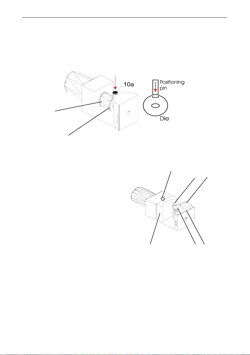
Punching ovals
1. Insert the pin positioning the die [10a];
2. Select a required punch [9] and die [10];
3. Fit the die and the punch;
4. Set the punching and profiling segment [2] at a required height with the use of
the crank [6] according to the ruler [7];
5. With the vertical ruler [8] set the hole distance from the bar end [8];
6. Start the machine [W1];
ERKO company reserves the right to technical changes improving/modernizing its products.

6
7. Select machining mode with the selector [W3] to punching; punching is not
allowed in the profiling position;
8. Press pedal [W2] to initiate punching holes;
9. Continue the punching process until the sensor [W6] lights – (erratic running);
10. After the hole has been punched, depress pedal [W2] and the punch will
return to its initial position.
Fig. 1 and Fig. 2 illustrate particular elements.
Profiling
1. Insert the pin [11] and the profiling insertion [12];
2. Set the punching and profiling segment [2] with the use of the crank [6] so the
middle part of the profiling bar was positioned with the segment servo-motor
axis [2];
3. Set a required profiling angle at the scale [13] by releasing and clamping [14];
4. Start the machine [W1];
5. Select machining mode with the selector [W3] to profiling;
6. Press pedal [W2] to initiate profiling action;
7. Continue the profiling process until the extreme position selector [W4] lights –
(erratic running);
9. After the bar has been profiled, depress pedal [W2] and the profiling insertion
[12] will return to its initial position.
Fig. 1 and Fig. 3 illustrate particular elements.
Offsetting
1. Fit the offsetting insertion [17];
2. Set the punching and profiling segment [2] with the use of the crank [6] so the
middle part of the profiling bar was positioned with the segment servo-motor
axis [2];
3. Start the machine [W1];
4. Select machining mode with the selector [W3] to profiling;
5. Press pedal [W2] to initiate profiling action;
6. Continue the profiling process until the bar has been profiled;
7. After the bar has been profiled, depress pedal [W2] and the profiling insertion
[12] will return to its initial position.
Note: the offsetting insertion is not equipped with a run cycle switch. Offsetting
should be carried out only on the oval elements of the insertion. Prevent the bar
from pressing the flat element of the insertion.
Fig. 1 and Fig. 4 illustrate particular elements.
Working with an external die
1. Fit the external conductor [3] with a required die and fittings;
2. Start the machine [W1];
3. Select machining mode with the selector [W3] to external die;
ERKO company reserves the right to technical changes improving/modernizing its products.

7
4. Prepare the die for work;
5. Press pedal [W2] to activate the die;
6. After the work with the die has been completed, depress pedal [W2] and the
die piston will return to its initial position.
Fig. 1 illustrates particular elements.
4. Maintenance materials
1. Hydraulic unit – hydraulic oil L-HM 32 – (5 dm3);
2. Punching and profiling unit lifting bolt – lubricant ŁT – 46.
4.1 Hydraulic oil exchange and refill
1. Remove the side plate [21];
2. Oil exchange and refill should be carried out according to the instructions
included in the Technical and Operational Documentation of the hydraulic
unit.
4.2 Lubrication of lifting unit bolt
When required carry out according to the following steps:
1. Unfasten the crank [6];
2. Remove the front plate [11];
3. Lubricate the bolt.
5. Work Safety and hygiene manual
1. Only personnel familiar with the Technical and Operational Documentation
are to operate the SH/400 machining station.
2. Proper positioning of the operating elements should be checked prior to
starting the machining station SH/400.
3. The machine can be operated only when at full technical performance.
4. Prior to starting check the following:
- electrical power installation
- oil level in the hydraulic feeder tank
- state of the mobile elements
- hydraulic unit
5. Electrical power should be disconnected during daily checks and repairs in
order to prevent accidental machine starting.
6. Personnel should wear adequate protective gear while operating the
machine.
7. Use the SH/400 machining station only for its intended purpose.
ERKO company reserves the right to technical changes improving/modernizing its products.

8
8. Prevent debris collection around the machining station. In case of high dust
concentration, cover the machine.
9. Working without a shield is forbidden.
10. Starting while manipulating the machine (fitting and unfastening elements,
positioning the machining material) is forbidden.
11. Start the machine only after the preparation has been completed and when
there is no danger of body or machine damage.
6. Troubleshooting
Problem Cause Solution
1. After starting the machine the
power diode does not light
a. no power supply
b. no 1 phase
c. voltage fall to
175V/phase
Check the power
supply
2. The machine switches off
while running
a. no phase at
engine
b. engine alarm went
off
c. no power supply
Check power supply
and engine alarm
3. Loud pump running with no
servo-motor motion
d. cover not closed
e. electrovalve has
broken
Close the cover
correctly. Contact
service.
ERKO company reserves the right to technical changes improving/modernizing its products.

9
7. Electrical diagram SH/400
Z1 – bending machine coil
Z2 – cutting machine coil
Z3 – die coil
W7 – cutting extreme position
W9 – profiling extreme position
W6 – punching extreme position
W8 – shield extreme position
W5 – angle extreme position
W3 – machining mode selector
W1 – main power switch
W4 – circuit-breaker
W3 – ŁK16R-4.858/PO3
W4 – XB2-ES542
W5 – TM1306
W6 – PCID-1, 5RP-NC MB
W7 – TM1701
W8 – TM1306
W9 – PCID-1, 5RP-NC MB
L1-L5-24V/2W
Z1-Z3-24V/0.75W
S1-FA-M250 2.5-4A
S2-KM-DILEM-10(24V50Hz)
ERKO company reserves the right to technical changes improving/modernizing its products.

10
W2 – pedal
W1 – ŁK16R-2.821/PO3
W2 – XPER310
S3-R15-1012-23-1024-D
B1-0.5A
B2-1A
T1-TR363 63VA
8. Spare parts specification
No. Part No. of pcs Manufacturer Drwg. ref. no.
Hole punching unit
1 Die M6 1 ERKO SH-400/02.11
2 Die M8 1 ERKO SH-400/02.11
3 Die M10 1 ERKO SH-400/02.11
4 Die M12 1 ERKO SH-400/02.11
5 Die M16 1 ERKO SH-400/02.11
6 Die M20 1 ERKO SH-400/02.11
7 Spring M16-M20 10 Pol Aston SH-400/02.14
8 Punch M6 1 ERKO SH-400/02.13
9 Punch M8 1 ERKO SH-400/02.13
10 Punch M10 1 ERKO SH-400/02.13
11 Punch M12 1 ERKO SH-400/02.13
12 Punch M16 1 ERKO SH-400/02.13
13 Punch M20 1 ERKO SH-400/02.13
14 Die 8,5/12 1 ERKO SH-404/01/02
15 Die 11/16 1 ERKO SH-404/01/02
16 Die 13/18 1 ERKO SH-404/01/02
17 Die 17/21 1 ERKO SH-404/01/02
18 Punch 8,5/12 1 ERKO SH-400/01/01
19 Punch 11/16 1 ERKO SH-400/01/01
20 Punch 13/18 1 ERKO SH-400/01/01
21 Punch 17/21 1 ERKO SH-400/01/01
22 Cover of spring PUR 10 ERKO SH-400/02/12
23 Pin 1 ERKO SH-404/01/03
Offsetting
24 Offsetting insertion pin 1 ERKO SH-400/03/00
25 Offsetting insertion punch 1 ERKO SH-400/03/00
Profiling unit
26 Profiling insertion 1 ERKO SH-400/02.02
27 Pin 1 ERKO SH-400/02.03
28 Electrical unit as in Diagram
29 Hydraulic feeder as in Annex 1
ERKO company reserves the right to technical changes improving/modernizing its products.

11
9. Figures
Conductor-rail machining station
SH/400
Fig. 1 General view
W1 W2
11
W3
L1,L2,L3L4
21
W4
L5
3
52
8
W7 1
3,
14
7
6
1
4
15
ERKO company reserves the right to technical changes improving/modernizing its products.
12
Fig. 2 Punching and profiling segment – punching holes
10
9
Fig. 3 Punching and profiling segment – profiling
Fig. 4 Punching and profiling segment – offsetting
W6
11
W5
13
14
12
ERKO company reserves the right to technical changes improving/modernizing its products.
13
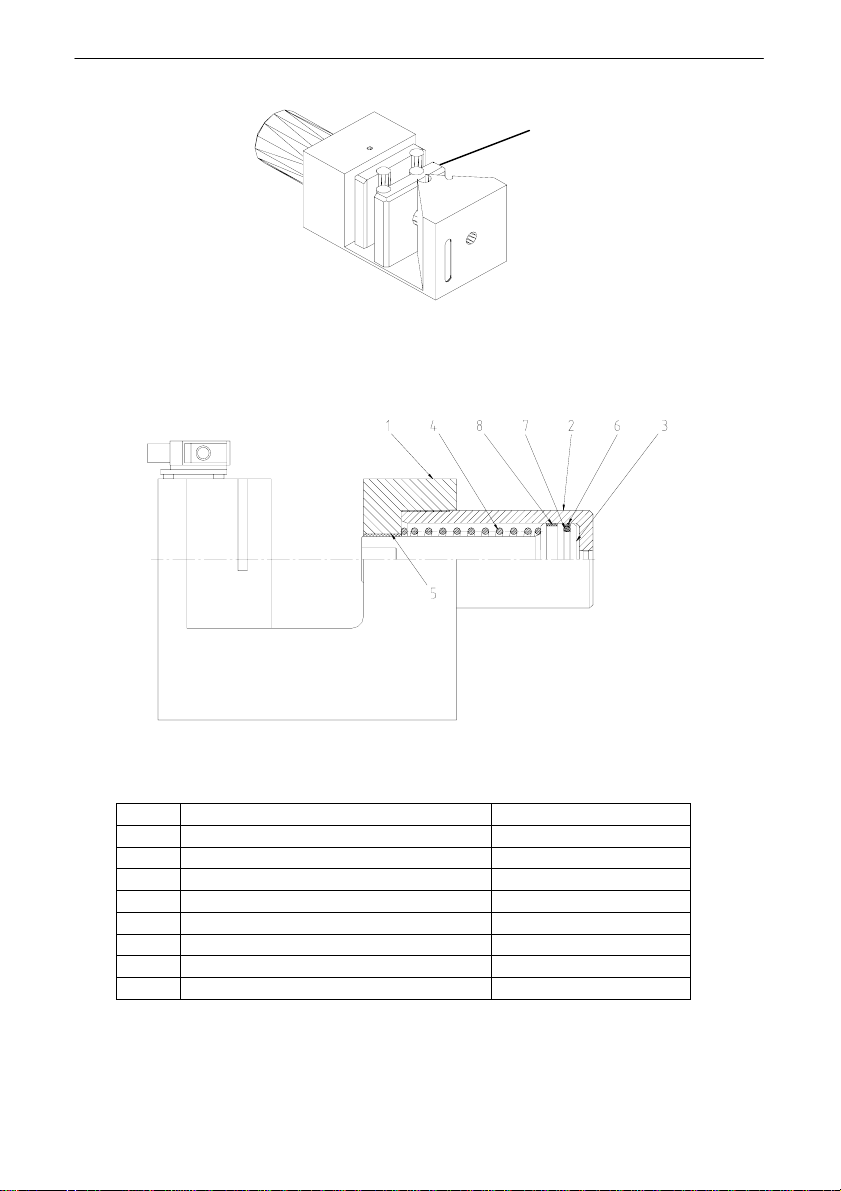
Fig. 5 Punching and profiling segment – cross-section
No. Element Drwg. ref. no.
1 Body SH-400/02.01
2 Cylinder HGD-100/01.06-A
3 Piston SIH-63/01.02
4 Spring SIH-63/01.03
5 Guiding barrel (Igus) GSM-4044
6 Insulation (Busak&Schamban) PS1400630-T46N
7 O-ring (Busak&Schamban) ORID04750
8 Guiding ring (Busak&Schamban) GP6900630-C380
17
ERKO company reserves the right to technical changes improving/modernizing its products.
14
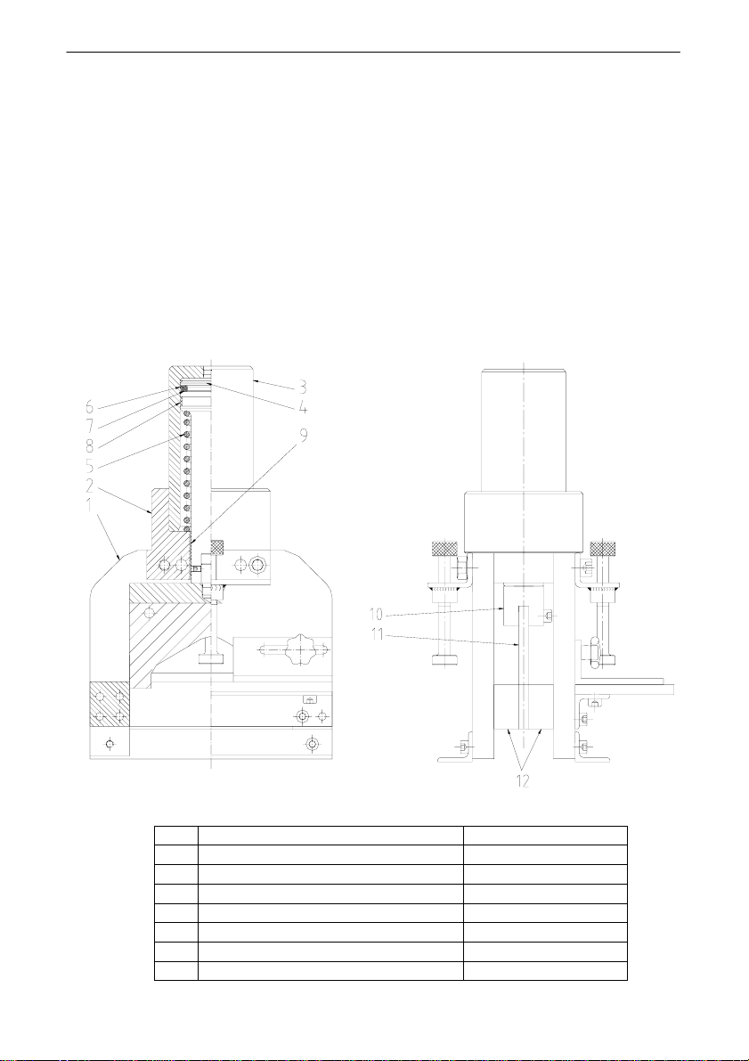
Fig. 6 Cutter – cross-section
No. Element Drwg. ref. no.
1 Body SH-400/01.01(02)
2 Connector SH-400/01.03
3 Cylinder HGD-100/01.06-A
4 Piston SIH-63/01.02
5 Spring SIH-63/01.03
6 Insulation (Busak&Schamban) PS1400630-T46N
7 O-ring (Busak&Schamban) ORID04750
ERKO company reserves the right to technical changes improving/modernizing its products.

15
8 Guiding ring (Busak&Schamban) GP6900630-C380
9 Guiding barrel GSM-4044
10 Knife fitting SH-400/01.05
11 Mobile knife SH-400/01.04
12 Permanent knives (2pcs) SH-400/01.07
10. Hydraulic unit
Technical and Operational Documentation
10.1. Introduction
Read the following Technical Description before operating the hydraulic feeder. The
hydraulic unit can only be operated by personnel trained in work safety and hygiene as
well as in the construction and the operation of the unit.
10.2. Technical description
Technical specifications
- power output (electric engine) 1.1 kW
- max. pressure 700 bar
- nominal efficiency 1.25 l/min
- power supply voltage 380 V, 50 Hz
- operation 24 V DC
- working medium L-HM-32 (Gdańsk Refinery)
- tank capacity ~ 5 dm3
Unit construction
This compact feeder consists of an oil tank and built-in hydraulic elements.
The main elements of the feeder are: a pump system V1 (pump and engine
submerged in oil), a press-return filter and a distributor. The tank construction enables
attachment. The hydraulic system of the unit is terminated with outputs G1/4 type.
The feeder is equipped with an oil level indicator.
ERKO company reserves the right to technical changes improving/modernizing its products.
16
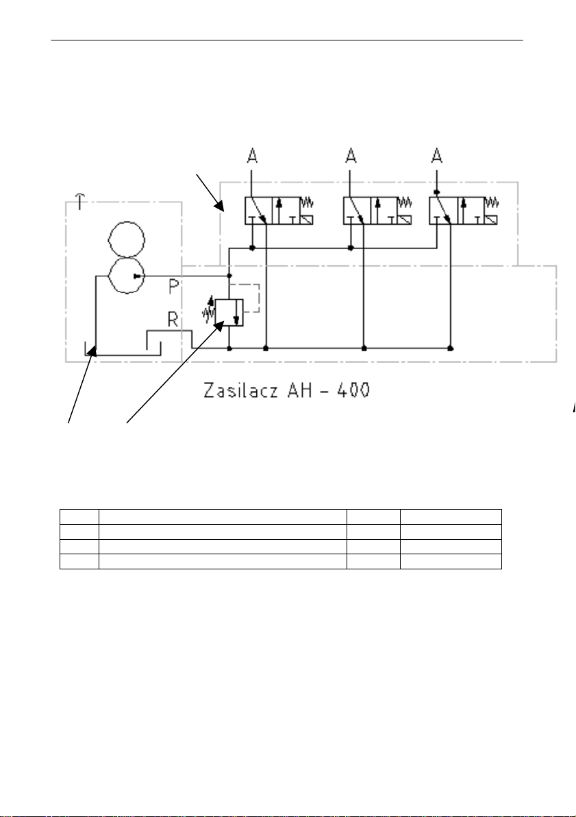
10.3. Hydraulic diagram
Feeder AH-400
3
1 2
10.4. Main parts specification
No. Part Pcs
1 Hydraulic system HC-31 HAWE 1 set
2 Emergency valve A2/700 (700 bar) HAWE 1 pc.
3 Emergency valve MVG 13 HR (400 bar) HAWE 1 pc.
10.5. Operation manual
Operation according to the Technical and Operational Documentation SH/400
The manufacturer set the maximum working pressure at the emergency valve at 400
bar or 680 bar (depending on the order) for the external die and at 680 bar for the
machining station unit. These values cannot be changed (safety leaden seals).
ERKO company reserves the right to technical changes improving/modernizing its products.

17
Caution:
- After finishing operation of the station switch off the power supply with the main
switch and cut-off from the main power supply by unplugging from power outlet.
- Switch off electrical power supply and release the hydraulic system while carrying out
any maintenance or repairs.
- The feeder generates high pressure. Operate the unit with great caution. Unit
unsealing may bring unexpected results. Entire system including the working elements
should be shielded for operator’s safety.
- Breaking leaden seals will void guarantee for the entire hydraulic system of the
machining station SH-400.
10.6. Maintenance manual
Switch off the power supply when carrying out any maintenance jobs (by turning the
main power supply switch to “0” position and unplugging from the power supply outlet).
Electrical power installation should be maintained regularly.
Particular attention should be paid to possible oil leaks. If any, remove them
immediately.
Check the oil level in the tank with the indicator under the electrical plate. Oil should fill
the capillary vessel located at the side of the hydraulic oil tank. Oil should be
exchanged every 12 months (if operated intensively – every 6 months). A tank
cleanliness check after removing old oil and before refilling new oil is recommended.
The suction filter cleanliness should be checked as well. If required, it should be
washed or replaced with a new one. After a refill, oil should fill the capillary vessel of
the oil indicator. Use HLP class oils of ZS-32 viscosity (e.g. AZOLLA ZS-32-TOTAL,
ELFOLNA DS 32 – ELF, TELLUS OIL 32 – SHELL, HYSPIN 32 – CASTROL,
ENERGOL HLP 32 – BP, NUTO H 32 – ESSO). The manufacturer recommends L-
HM32 - Gdańsk Refinery oil.
Remove air from the pump after an oil refill. To do so, set the cutting mode and initiate
the pump with short cycles (2 sec.) until the die servo-motor reaches the extreme
position. Repeat this procedure in case of loud and non-uniform unit operation and
lack of force. Skipping this procedure will prevent obtaining high pressures and in
extreme situations will result in pump seizure.
Maintaining oil purity and periodical oil exchanges has a great effect on the durability
of the hydraulic unit elements and considerably prolongs their performance and
reliability. Required oil purity: class 9 (recommended class 8) according to the NAS
1638 norm.
System tightness, removal of any oil leaks and oil level checks should be carried out
daily when operating the unit.
In case of a unit break-down, switch off electrical power supply and consult a specialist
service representative. Repairs within the guarantee period can only be carried out by
the manufacturer or authorised representatives.
ERKO company reserves the right to technical changes improving/modernizing its products.

18
11. The warranty
1. This warranty covers product repairs on condition that it is operated in
compliance with its instructions’ manual.
2. The guarantee period is 12 months from the purchase date.
3. The manufacturer guarantees full technical support in Poland.
4. Parts and materials which are to be exchanged during the correct usage of
the product (oil, filter inputs etc.) are not under the guarantee. Parts and
materials provided by cooperating companies are guaranteed on their
conditions.
Other repairs will be performed at least 3 days after the date of complaint.
5. This warranty does not concern damages caused by improper usage,
maintenance, transportation and storage of the product.
6. The guarantee will become void if any unauthorised modification is performed
on the product.
7. This guarantee will also be void if the manufacturer’s leaden seals of unit
safety valve are broken.
8. Operational requirements also concern the purity of oil and its adequate
hydraulic level. It always has to be class 9 according to the NAS 1638 norm,
otherwise the guarantee is void.
9. In order to make a complaint it is necessary to deliver the product with the
guarantee card and detailed damage description to the manufacturer or to the
point of sales.
10. The manufacturer is not responsible for damages caused by product’s
defects. Neither these damages repairs nor expenses and lost income return
is under the guarantee.
Purchasing date: Invoice no.: Sales representative
signature:
Dear User,
Thank you for selecting this product and welcome you to the growing
family of our satisfied product owners.
Any remarks or suggestions to our products will be greatly appreciated.
ERKO®, manufacturer
ERKO® has the right to make improvements to the machine construction.
ERKO company reserves the right to technical changes improving/modernizing its products.

19
12. Guarantee certificate
Name/type: Conductor-rail Machining Station SH-400
Manufacture no.
Signature and stamp KJ:
Invoice no.:
Date sold:
Date purchased:
Sales Representative signature:
Sales Representative signature:
13. REPAIR LIST
No. Date of receipt for repair Date of repair
(return)
Repair
remarks
Signature of
serviceman
ERKO company reserves the right to technical changes improving/modernizing its products.
Table of contents


