CHESTER Crusader Deluxe Lathe User manual


Contents
1. GENERAL DESCRIPTION OF THE MACHINE
General Description
Basic Technical Data
2. DESCRIPTION OF THE MAIN UNITS
Gearbox
Quadrant
Feed Box
Carriage Group
Thread Indicator
Tail Stock
Rests
3. MACHINE INSTALLATION
Unpacking
Handling
Preparation
Mounting, Foundation and Levelling
Connection to the Electrical Supply
Putting into Operation
4. MACHINE SERVICE
Lubrication
Recommended Lubricants
5. MACHINE OPERATION
Putting into Operation
Cutting of Threads and Feeds
Fretted Parts
6. MECHANISMS ADJUSTMENT
7. SAFETY
8. MACHINE CARE AND MAINTENANCE
9. TRANSMISSION SYSTEM & PARTS
10. BEARING DISTRIBUTION

1. GENERAL DESCRIPTION OF THE MACHINE
1.1General Data
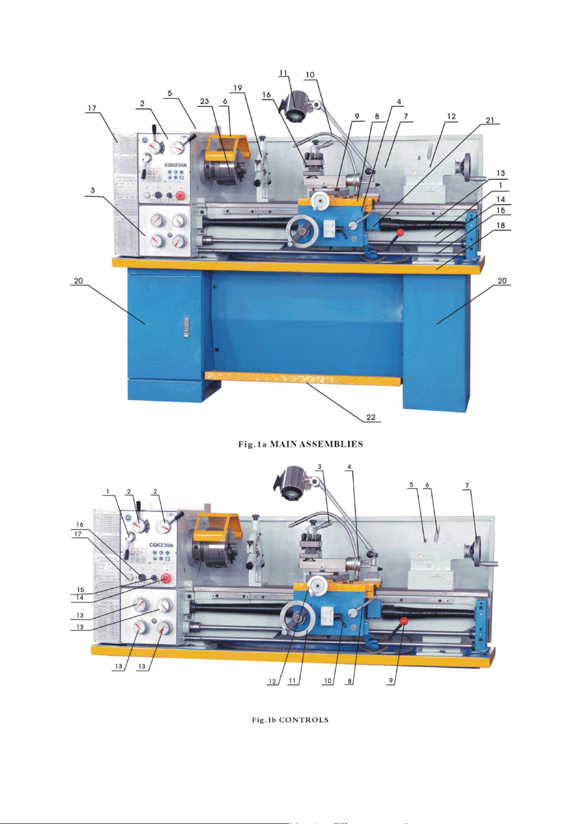
Main Assemblies (see fig 1a)
1. Bed way 13. Lead screw (with guard)
2. Headstock 14. Feed rod
3. Feed box 15. Switch rod
4. Carriage box 16. Tool holder
5. Electrical box 17. Quadrant
6. Chuck protection box 18. Oil tray
7. Splash guard 19. Steady rest
8. Lower carriage 20. Foot stand
9. Top carriage 21. Thread indicator
10.Cooling 22. Foot brake
11.Working Light 23. 3 jaw chuck
12.Tailstock
Controls (see fig 1b)
1. Lever for starting, stopping and reversing the carriage feed movement while
threading
2. Lever for spindle speed stages
3. Wrench for the tool holder
4. Flywheel for the shifting the tool holder slide
5. Handle for the tail spindle fixing
6. Handle for the tailstock fixing
7. Flywheel for the tail spindle shifting
8. Handle for the starting and stopping of the carriage longitudinal shifting while
threading
9. Lever for starting the spindle in forward or reverse stroke and its stopping.
When shifted in the forward direction, the spindle will turn counter-clockwise,
and when shifted in the backward direction, the spindle will turn clockwise.
When in the center position, the spindle will stop.
10.Lever starting and stopping the carriage in transverse and longitudinal shifting
11.Flywheel for manual shifting of the carriage in longitudinal direction
12.Flywheel for feeding the cross slide
13.Drum (handle) for selection of “feed” or “thread”
14.Button-emergency stop
15.Switch-coolant pump
16.Button-test bottom for the main electric motor
17.Signal lamp. It glows when the main electric motor is switched on

1.2 Basic Technical Data
Crusader Deluxe Lathe
Max swing over bed
300mm
Max swing over gap
430mm
Max swing over cross slide
180mm
Distance between centers
810mm
Spindle bore
38mm
Range of spindle speed
18 steps: 65-1810rpm
Taper of spindle bore
M.T.5
Taper of tailstock spindle
M.T.3
Max travel of carriage
600mm
Max travel of cross slide
160mm
Max travel of top slide
85mm
Max travel of tailstock spindle
100mm
Motor power
1.1kW

2. DESCRIPTION OF THE MAIN UNITS
Gear Box
The gear box is mounted on the machine corp. The rotation motion to this gear
box is transferred though v-belts and belt pulleys from an electric motor mounted
on the guide way.
Quadrant
The quadrant is designed to transfer the motion from the gear box to the feed box
through the change gears. It is mounted in the quadrant box. The latter is closed
by a cover.
Feed Box
The feed box is foxed to the face side of the machine corp –just below the gear
box. It includes allthe mechanisms, by thehelp of which iseffected the adjustment
for selection of the feed or thread pitches.
Required adjustments for the different values of the feed or thread pitch are
realized by the help of respective drums, located in the front part of the feed box.
Carriage Group and its Mechanisms
The carriage group is designed for fixing and driving the cutting tool. It includes
five basic parts: carriage box, carriage board, lower slide, cross piece and upper
(top) slide.
1. Carriage box
The carriage box ismounted on the carriage board. It contains the mechanisms
that are used for driving the carriage longitudinal and cross feeds, as well as
the mechanism for the engagement of the nut to the lead screw while threading
and the mechanism for manual feed of the carriage.
2. Carriage Board
The carriage board is mounted on the corp guide ways. All the rest parts of the
carriage group are fixed to this carriage board.
3. Lower Slide
The lower slide moves on the guide ways of the carriage board in a transverse
direction. This movement may be effected automatically or manually.
4. Cross Piece
When short cones have to be turned by hand, the cross piece may be swiveled
at 90° towards the lower slide in both directions and be fixed in the required
position by the help of suitable bolts and nuts.
5. Upper (Top) Slide

The top slide on which the four position tool holder is mounted, can be shifted
only by hand in the direction of the cross piece.
Thus you may obtain longitudinal, cross and combined feed for the cutting tool.
Thread Indicator
This device is mounted to the carriage box (disengaged to the driving screw) for
getting into the thread pitch.
Tail Stock
The tail stock is clamped to the corp guide ways. It is designed for working piece
clamping during machining between centers for drilling operations with manual
feed of the tool.
Rests
In response to the special request of the client, the lathe may be packed
additionally with a steady and a follow rest.
The two types are with sliding quills. The steady rest is fixed to the corp guide
ways and the follow rest to the carriage board.

3. MACHINE INSTALLATION
Unpacking
After the machine has been unpacked, check carefully its general condition as well
as the condition of all the accessories.
Handling
The unpacked machine shall be moved onlyby the help of a suitable crane. Before
passing the ropes over the specified places, see fig 2, pull out the tail stock and
carriage and fix them in the rear hand position so that when lifting the machine you
will obtain the required balance. When moving the machine, never strike or hit it
sharply as this may affect the machines accuracy irrespective of whether or not
there is any visible defects.
Since the paint on some parts of the machine maybe damaged duringthis process,
place protective pads of fabric or other suitable material on the respective places.
Preparation
Before placing the machine in the predetermined position, clean it carefully from
the protective oil. The machine surfaces should be cleaned with pure naphtha or
benzine.
Do not use hard objects or any solvent that could damage the metal surfaces or
the paint of the machine. Use dry cloths to dry any damp surfaces of the machine
and coat with machine oil to help protect the clean surfaces. Remove the end gear
cover and clean all components of the end gear assembly and coat all the gears
with heavy non-slinging grease.
Mounting, Foundations and Levelling
To obtain accurate, durable and trouble-free operation of the machine, mount it
only on a suitable foundation and level the machine carefully. The foundation is to
be prepared in advance with concrete with a thickness from 200 to 300mm
according to the soil type.
The unpacked machine is lifted by crane according to the specified method and
after the anchor and leveling bolts are in place, lower the machine onto the
foundation so that anchor bolts enter into the respective holes in the machine base.
The guide way should be checked horizontally in the longitudinal and transverse
direction towards the machine axis by the help of a spirit level with an accuracy of
+/- 0.02/1000mm and +/- 0.04/1000mm. After this initial levelling has been carried
out, pout cement putty into the space below the machine legs around the anchor
bolts.
After the cement has set (3-4 days), tighten the nuts of the anchor bolts carefully
and evenly. Check the machines level again and if necessary correct using the
leveling bolts.
Connection to the Electrical Supply
Check that the data on the electrical panel scheme (voltage and frequency of the
supply source) correspond to the power supply available.
The controlling level should remain in the middle and also press the power switch
down to keep the machine switched off.
Make sure that the machine is properly grounded.
Putting into Operation
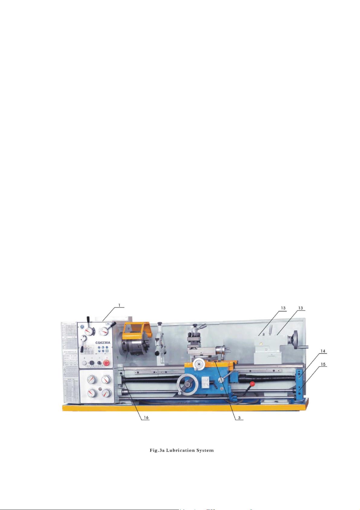
Before starting the machine, clean it once again and lubricate according to the
diagram, see fig 3a, 3b and 3c.
Check the V-belt from the motor to the gear box and make sure that it is not too
tight or too loose. If the belt is too tight, it could damage the bearings, if the belt is
too loose, it will slip. Adjust must be adjusted to the correct tension.
Starting is effected in the following order:
Check manually the movements of all the components. It should be smooth.
Check all the controls are operating correctly.
Fill the tank of the coolant system with the specified coolant (optional accessory
order separately). Switch on the main electric motor.
After one hour check the oil levels in the tanks and, if necessary, add the oil
quantity required.
After two shifts of operation, check the V-belts for excessive play.


4. MACHINE SERVICE
Lubricant
The trouble-free operation of the lathe depends on careful servicing, especially the
regular lubrication of all machine operating parts with the recommended lubricants,
see fig 3a, 3b and 3c.
The headstock is lubricated by the splashing of oil. The oil may be poured into
headstock after the removal of the cap (1) from the oil vent with the oil filler located in
the headstock cover. The oil is drained by unscrewing the plug (1-1) to the oil draining
tube. If the oil has be replaced, clean the headstock with pure naphtha carefully.
When refilling with new, the level must be to the middle of the oil sight glass. The disk
couplers and the main spindle front bearing are lubricated by an oil collecting groove.
The feed box is lubricated through a hole (2) located on its left hand side. The oil
quantity required must reach the middle of the sight glass. The oil is drained through
the plug (2-2).
The change gear sleeve for the quadrant should be lubricated with grease once per
day with a suitable oiler. The change gears should be lubricated with oil once per day.
The carriage box is lubricated through a common hole (3) where the oil is fed into a
tank which is common for the whole box. Using suitable grooves, the oil is fed to the
respective bearing as a portion of the oil drops on the bottom of the box from where
the gears are oiled. The oil is drained from a plug (3-3).
The carriage as well as the slide guiding surfaces are lubricated by the help of suitable
oilers (6) pressed into the carriage and cross slider (8). The electric motor bearing
should be cleaned and greased once every six months. All the friction surfaces of the
carriage, travelling stock and conic lineal should be oiled by the help of an oil holder
or oiler according to the lubrication system.

Recommended Lubricants
Assembly
Lubricating
point
Lubricating
Method
Lubricant
Lubricating
Interval
Headstock
Gears and
bearing,
Spindle fron
bearing,
Spindle rear
bearing, Belt
pulley bearing
Oil bath - by
splashing
Machine
Oil
Oil replacement:
1st time - after
10 days of
operation, 2nd
time - after 20
days of
operation, next
time - once per
each 60 days
Feed box
Gears, bearings
and all the
mechanisms
Oil bath - by
splashing
Machine
Oil
Carriage
Gears, bearings
and all the
mechanisms
Oil bath - by
splashing
Machine
Oil
Quadrant
Change gears,
Quadrant idle
axel
By Hand
Machine
Oil, Grease
"L"
Once per shift
Carriage
slide
Corp bed ways,
Slide bed ways
By Hand with
help of oilers
Machine
Oil
Once per shift
Cross
carriage
Support of the
screw in the
slide. Cross
screw for
carriage
By Hand oil tank,
located in the
carriage
Machine
Oil
Once per shift
Cross
shaped
carriage
Carriage bed
ways. Cross
shaped carriage
bed ways,
Screw of the
cross shaped
carriage, Tool
holder
By Hand
Machine
Oil
Once per shift
Tailstock
Screw support
Quill
By Hand
Machine
Oil
Once per shift
Console
Lead screw
bearing, feed
rod bearing,
switch rod
bearing
By Hand
Machine
Oil
Once per shift

5. MACHINE OPERATION
Putting into Operation
After performing the previous instruction, the machine is ready for operation, the
connection to the electric supply is effected by the help of the main interrupter.
Turning on the control lamp shows that the machine is connected to the power
supply.
All the speeds within the range 65-1810rpm at different position of the levers are
shown on the nameplate.
When starting the machine, check that all the gears are engaged, this is obtained
by placing the handles at their fixed positions.
The change-over of the gears shall be effected only under idling conditions.
The machine operating mode selection shall be realized from the speed indication
nameplate. When trying the machine, put the speed change lever in low speed
stage and keep the machine running for at least 20 minutes, the gradually change
the speed of the spindle up to the fasted. Every stage running over 5 minutes.
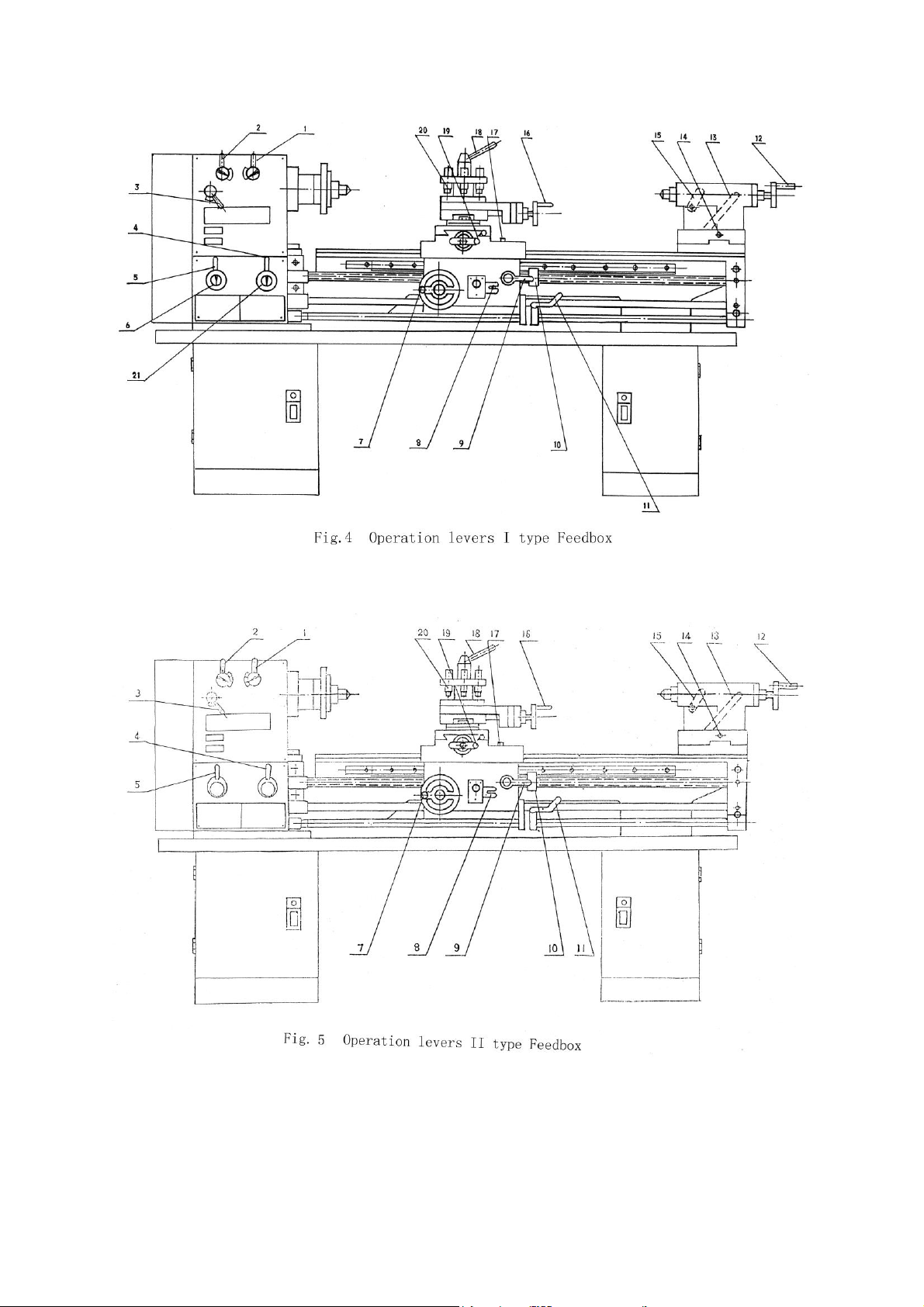
Cutting of Threads and Feeds
The feed box receives it motion from shaft V of the gearbox through a set of change
gears. If the handle (3), see fig 4, 5 and 6, is placed in its right hand position, the
lathe is set for cutting of right hand thread. If the same handle is placed in its left
hand position, the lathe is set for cutting of a left hand thread.
It is not required to place on the quadrant respective change gear set in order to
prepare the lathe for the necessary feed.
The different values for the feeds and threads are obtained by the different setting
of the quadrant and changing the position of drums/handle 4, 5, 6, 21 and handle
3.
All the quadrant setting and drums/handles different positions are shown on the
nameplate for threads and feeds.

Adjust the nut gap on the carriage, see fig 7.
Rotate the nut (1) to the satisfied saddle motion and required travel.
Chuck and faceplate mounting, see fig 8.
The connection between the spindle and the chuck or faceplate is made by a D-
Cam lock structure. When mounting, put the three pull pins of the chuck or
faceplate into the three holes on the spindle face end, then turn the three cams
with the aid of a square head wrench. When turning thecams clockwise, the chuck
will be locked, when turning the cams counter-clockwise to a certain point, the
chuck can be detached.
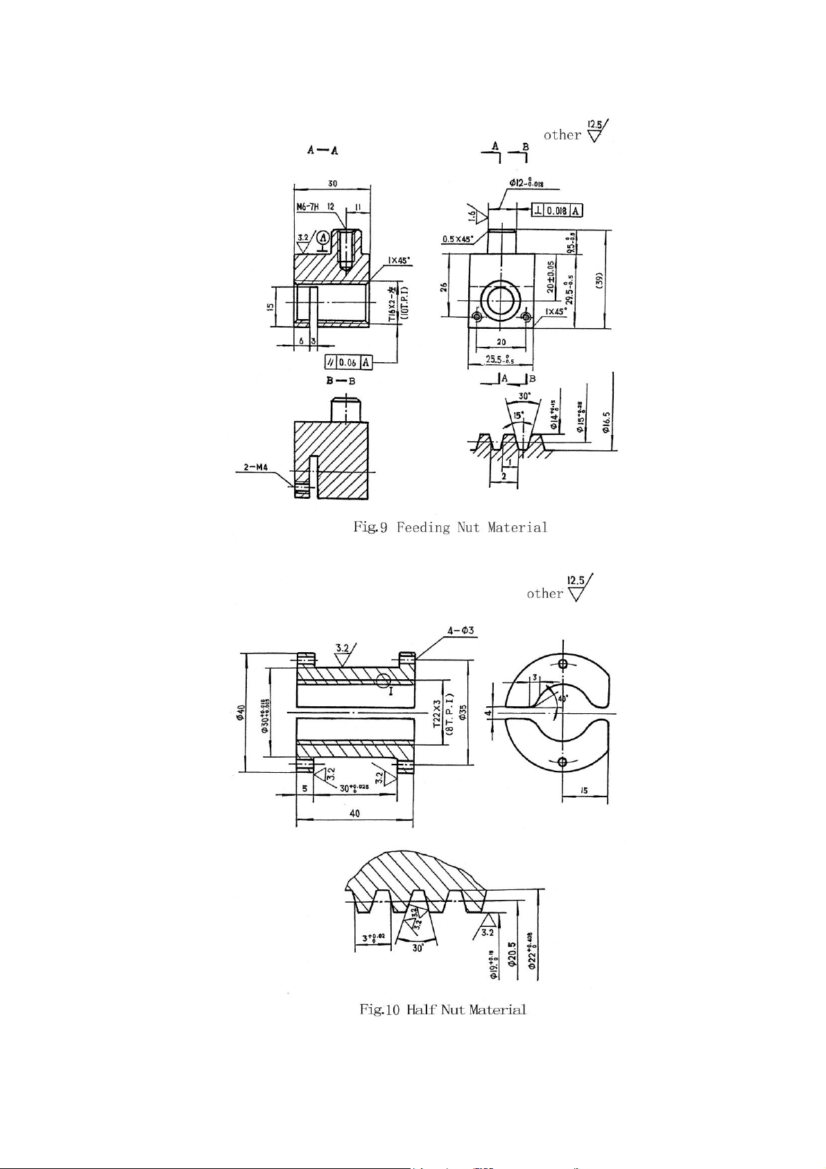
Fretted Parts
No.
Name
Material
Mount
Note
1
Feeding Nut
ZQSn6-6-3
1
CQ6230-5104
2
Half Nut
ZQSn6-6-3
1
CQ6230-4003

6. MECHANISMS ADJUSTMENT
After a period of time, some of the mechanisms will require readjustment because
of the effect of wear and tear on the friction surfaces. The adjustment and setting
of the different mechanisms shall be effected after each repair. It is recommended
that these adjustments are performed by a qualified specialist.
7. Safety
All lathe operators must be constantly aware of the safety hazards that are
associated with using the lathe and must know all the safety procedures to help
avoid accidents and injuries.
Please follow the following safety precautions:
1. Remove loose clothing and jewelry, tie back long hair and roll sleeves up above
the elbow. Do not operate whilst wearing gloves
2. Always stop the lathe before making adjustments.
3. Do not change the spindle speeds until the lathe has come to a complete stop.
4. Handle sharp cutters, centers and drills with care.
5. Remove chuck keys and wrenches before operating the machine.
6. Always wear protective eye protection.
7. Handle the chuck with care and protect the lathe guide ways with a block of
wood before replacing or installing the chuck.
8. Make sure you know where the emergency stop button is before operating the
machine.
9. Use pliers or a brush to remove chips and swarf, never use your hands.
10.Do not lean on the machine.
11.Never lay tools directly on the guide ways.
12.Keep tool overhang as short as possible.
13.Never attempt to measure work whilst the machine is running.
14.Never file lathe work unless the file has a handle.
15.Do not over reach. Maintain a balanced stance at all times so that you do not
fall or lean against blades or other moving parts.
16.Provide adequate light around the machine and keep the perimeter around the
machine dry, clean and in good order. In addition, do not place anything near
the machine; otherwise it becomes an obstacle during operation.
17.Keep machine guards in place at all times when the machine is in use. If
removed for maintenance purposes, use extreme caution and replace the
guards immediately.
18.Keep the floor around the machine clean and free of scrap material, oil and
grease.
19.Always use identical replacement parts when servicing.

8. MACHINE CARE AND MAINTENANCE
Lathes are a highly accurate machine tool designed to operate around the clock is
properly operated and maintained. Lathes must be lubricated and checked for
adjustment before operation. Improper lubrication or loose nuts and bolts can
cause excessive wear and dangerous operating conditions.
1. The lathe ways are precision ground surfaces and must not be used as a table
for other tools and should be kept clean of grit and dirt.
2. The lead screw and gears should be checked frequently for any metal chips
that could be lodged in the gearing mechanisms.
3. Check the lathe prior to operation for any missing parts or broken shear pins.
Refer to the manual before attempting to lift the lathe.
4. Newly installed machines should be properly leveled before operation to
prevent vibration or wobble.
5. When the lathe is transported out of a normal shop environment, it should be
protected from dust, excessive heat and very cold conditions.
6. Change the lubricant frequently if working in dusty conditions.
7. In hot working areas, use care to avoid overheating the motor or damaging any
seals.
8. Operate the lathe at slower speeds than normal when working in cold
environment.
9. Lubricate all slide ways lightly before using the machine daily. The change
gears and lead screws must be lightly lubricated with lithium base grease.
10.During the operation, the chips which fall on to the sliding surface should be
cleared in a timelyfashion, an inspection should be made often to prevent chips
falling between the machine tool saddle and the lathe bed guide way. Asphalt
felt should be cleaned a certain interval.
11.After the operation every day, eliminate all the chips and clean the different
parts of the machine and apply machine tool oil to prevent rusting.
12.In order to maintain the machine accuracy, take care of the center, the surface
of the machine tool for the chuck and the guide way and avoid mechanical
damage and wear due to improper operation.
13.If damage is found, maintenance must be carried out immediately.
ATTENTION: Before performing any inspection, repair or maintenance operation,
switch off the main power supply to the machine and make an additional check to
ensure that the machine is not under voltage.
Oil, grease and cleaning are pollutants and must not be disposed of through the
drains or in normal refuse. Dispose of these agents in accordance with current
legal requirements on the environment. Cleaning rags impregnated with oil,
grease and cleaning agents are easily inflammable. Collect cleaning rags or
cleaning wool in a suitable closed vessel and dispose of them in an environmentally
sound way –DO NOT put them with normal refuse.

9. Transmission System & Parts
Parts
Parts
No.
Kinds
No. of
teeth
on
thread
Modulus
of pitch
Pressure
angle
Material
Notes
Headstock
1
Gear
42
M2
20°
45
2013
2
Gear
23
M2
20°
45
2018
3
Gear
47
M2
20°
45
2019
4
Gear
36
M2
20°
45
2021
5
Gear
55
M2
20°
45
2020
6
Gear
31
M2
20°
45
2022
7
Gear
45
M2
20°
45
2016
8
Gear
58
M2
20°
45
2015
9
Gear
21
M2
20°
45
2017
10
Gear
45
M2
20°
45
2008
11
Gear
59
M2
20°
45
2029
12
Gear
46
M2
20°
45
2030
13
Gear
83
M2
20°
45
2031
14
Paired
Gear
45
M2
20°
45
2026
40
M2
20°
45
15
Gear
40
M2
20°
45
2032
45
M2
20°
45
Feed Box
16
Gear
24
M2.25
20°
45
3029B
17
Gear
16
M2.25
20°
45
3031B
18
Gear
18
M2.25
20°
45
3032B
19
Triplicated
Gear
18
M2.25
20°
45
3005B
18
M2.25
20°
45
18
M2.25
20°
45
20
Gear
20
M2.25
20°
45
3003B
21
Gear
28
M2.25
20°
45
3002B
22
Gear
27
M2.25
20°
45
3027C
23
Gear
21
M2.25
20°
45
3025C
24
Gear
21
M2.25
20°
45
3018C
25
Paired
Gear
18
M2.25
20°
45
3026C
30
M2.25
20°
45
26
Gear
22
M2.25
20°
45
3007C
27
Paired
Gear
15
M2.25
20°
45
3006C
22
M2.25
20°
45
28
Gear
23
M2.25
20°
45
3009B
29
Gear
17
M2.25
20°
45
3016C
30
Gear
15
M2.25
20°
45
3014C
Apron
31
Gear
11
M2.25
20°
45
4028
32
Rack
M2.25
29° or
30°
45
33
Lead
Screw
Single
Thread
8TPI or
3mm
45

34
Halfnut
Single
Thread
MS2
20°
ZQSn6-
6-3
35
Worm
Single
Thread
MS2
20°
45
36
Worm
Gear
24
M2
20°
ZQSn6-
6-3
4017
37
Gear
15
M2
20°
45
4030
38
Gear
50
M2
20°
ZQSn6-
6-3
4029
39
Gear
25
M2
20°
45
4014
40
Nut
Single
Thread
10TPL or
2mm
ZQSn6-
6-3
Left
Hand
Thread
41
Screw
Single
Thread
10TPL or
2mm
45
42
Gear
14
M2
20°
45
4019
43
Gear
51
M2
20°
45
4013
44
Gear
43
M2
20°
45
5127
45
Gear
25
M2
20°
45
4010
46
Gear
48
M2
20°
45
4012
47
Screw
Single
Thread
10TPL or
2mm
45
48
Nut
Single
Thread
10TPL or
2mm
ZQSn6-
6-3
Tailstock
49
Rod Screw
Single
Thread
10TPL or
2mm
45
Left
Hand
Thread
50
Nut
Single
Thread
10TPL or
2mm
ZQSn6-
6-3
Left
Hand
Thread
Change
Gear
Gear
22
M1.25
20°
3076C
Gear
24
M1.25
20°
45
2002C
Gear
26
M1.25
20°
45
3075C
Gear
44
M1.25
20°
45
3077C
Gear
48
M1.25
20°
45
3039C
Gear
52
M1.25
20°
45
3039C
Paired
Gear
127
(120)
M1.25
20°
45
3078C
Table of contents
Other CHESTER Lathe manuals

CHESTER
CHESTER DB8VS User manual

CHESTER
CHESTER 920 User manual

CHESTER
CHESTER Cobra Mill User manual

CHESTER
CHESTER Crusader User manual

CHESTER
CHESTER CONQUEST SUPER LATHE User manual

CHESTER
CHESTER DB7VS User manual

CHESTER
CHESTER Craftsman User manual

CHESTER
CHESTER Centurion Series User manual

CHESTER
CHESTER Crusader VS User manual

CHESTER
CHESTER CONQUEST SUPER User manual


