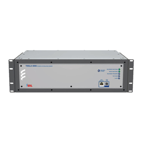
ERL TESLA 4000 User manual

TESLA 4000
Power System Recorder
User Manual
Version 2.6 Rev 0


D02771R02.60 TESLA 4000 User Manual i
Preface
Information in this document is subject to change without notice.
© 2015 ERLPhase Power Technologies Ltd. All rights reserved.
Reproduction in any manner whatsoever without the written permission of
ERLPhase Power Technologies Ltd. is strictly forbidden.
This manual is part of a complete set of product documentation that includes
detailed drawings and operation. Users should evaluate the information in the
context of the complete set of product documentation and their particular
applications. ERLPhase assumes no liability for any incidental, indirect or
consequential damages arising from the use of this documentation.
While all information presented is believed to be reliable and in accordance
with accepted engineering practices, ERLPhase makes no warranties as to the
completeness of the information.
All trademarks used in association with B-PRO, B-PRO Multi Busbar, Multi
Busbar Protection, F-PRO, iTMU, L-PRO, ProLogic, S-PRO, T-PRO,
TESLA, I/O Expansion Module, TESLA Control Panel, Relay Control Panel,
RecordGraph and RecordBase are trademarks of ERLPhase Power
Technologies Ltd.
Windows®is a registered trademark of the Microsoft Corporation.
HyperTerminal®is a registered trademark of Hilgraeve.
Modbus®is a registered trademark of Modicon.
Contact Information
ERLPhase Power Technologies Ltd
Website: www.erlphase.com
Email: [email protected]
Technical Support
Email: [email protected]
Tel: 1-204-477-0591


D02771R02.60 TESLA 4000 User Manual iii
Using This Guide
This User Manual describes the installation and operation of the TESLA power
system recorder and the accompanying TESLA Control Panel user interface
software. It is intended to support the first time user and clarify the details of
the equipment.
The manual uses a number of conventions to denote special information:
Example Describes
Start>Settings>Control Panel Choose the Control Panel submenu in the Set-
tings submenu on the Start menu.
Right-click Click the right mouse button.
Recordings Menu items and tabs are shown in italics.
service User input or keystrokes are shown in bold.
Text boxes similar to this one Relate important notes and information.
.. Indicates more screens.


D02771R02.60 TESLA 4000 User Manual v
Table of Contents
Preface ......................................................................................i
Contact Information ...................................................................i
Using This Guide ..................................................................... iii
Table of Contents .....................................................................v
Version Compatibility...............................................................ix
PC System Requirements and Software Installation...............xi
1 Overview ................................................................. 1-1
TESLA System Description.............................................. 1-1
TESLA 4000 Features ..................................................... 1-2
Front Panel ...................................................................... 1-6
Rear Connections ............................................................ 1-6
2 Installation and Safety Instructions ..................... 2-1
Introduction ...................................................................... 2-1
Physical Mounting............................................................ 2-2
Case Grounding............................................................... 2-3
Power Supply................................................................... 2-4
Signal Connections .......................................................... 2-5
3 TESLA Control Panel Installation ......................... 3-1
Installing TESLA Control Panel........................................ 3-1
Installation on Windows XP and Windows 7.................... 3-2
First Time Start-Up........................................................... 3-6
4 Communicating with the Recorder....................... 4-1
Communication Ports....................................................... 4-1
IRIG-B Time Input ............................................................ 4-3
Communicating with the Recorder (IED) ......................... 4-3
Ethernet LAN Link............................................................ 4-4
USB Link .......................................................................... 4-7
Direct Serial Link............................................................ 4-10
Modem Link ................................................................... 4-12
Modem LAN Gateway.................................................... 4-15
Accessing SCADA Services .......................................... 4-16
Communication Port Details .......................................... 4-21
IEC 61850 Communication ............................................ 4-24
5 Working with TESLA Control Panel ..................... 5-1

Table of Contents
vi TESLA 4000 User Manual D02771R02.60
Recorder Workspace ....................................................... 5-1
Adding/Editing a Recorder Workspace Definition............ 5-3
Online and Offline Operation ........................................... 5-5
Navigating in TESLA Control Panel ................................. 5-6
6 Metering Display .................................................... 6-1
7 Recorder Setup Utilities ........................................ 7-1
Unit Identification ............................................................. 7-2
Communication Port Settings .......................................... 7-3
Recording Control Settings .............................................. 7-5
Time Display and Settings ............................................... 7-9
Analog Input Calibration................................................. 7-12
Notify.............................................................................. 7-14
Password Protection ...................................................... 7-16
8 Configuring the Recorder..................................... 8-1
Managing Configuration Files .......................................... 8-1
SCADA and DNP Configuration....................................... 8-4
Configuration Editor ......................................................... 8-4
Identification..................................................................... 8-5
Channels and Triggers..................................................... 8-8
Analog Input Channels................................................... 8-17
External Input Channels................................................. 8-22
GOOSE Virtual Input Channels ..................................... 8-24
Summation Channel ...................................................... 8-26
Sequence Component Channels ................................... 8-29
Impedance Channels ..................................................... 8-32
Watts and Vars Channels .............................................. 8-35
Frequency Channels...................................................... 8-38
Logic Functions.............................................................. 8-41
Fault Locator Functions ................................................. 8-43
Power Factor Functions................................................. 8-45
Meter Groups ................................................................. 8-48
Trend Logging................................................................ 8-49
Printing........................................................................... 8-51
9 Record and Log Management............................... 9-1
Records............................................................................ 9-1
Trend Log......................................................................... 9-4
Event Log......................................................................... 9-6

Table of Contents
D02771R02.60 TESLA 4000 User Manual vii
10 Continuous Disturbance Recording................. 10-1
11 Graphing Records.............................................. 11-1
Getting Started............................................................... 11-1
RecordGraph Menu Items.............................................. 11-6
Views ........................................................................... 11-32
Graphs ......................................................................... 11-34
Templates .................................................................... 11-57
View and Graph Titles.................................................. 11-63
Readouts and Measurements...................................... 11-65
Calculated Channels.................................................... 11-72
Exporting Views ........................................................... 11-73
Exporting Channel Data............................................... 11-74
Record Summary ......................................................... 11-76
Digital Channel Status Indicator................................... 11-77
Time Sync Input Status................................................ 11-77
Derived External and Virtual Input Channels for TESLA
Swing Recordings ........................................................ 11-78
COMTRADE Import ..................................................... 11-78
Print Options ................................................................ 11-80
12 Record Export Utility ......................................... 12-1
COMTRADE Format ...................................................... 12-3
PTI Format .................................................................... 12-5
Excel (CSV) Format ....................................................... 12-7
IEEE C37.232 TSD File Naming.................................... 12-9
13 Cooperative Recorder Group............................ 13-1
How A Cooperative Recorder Group Works.................. 13-1
Setting Up a Cooperative Recording Group .................. 13-4
Working With Records From a Cooperative Recording
Group ........................................................................... 13-12
Required Cooperative Mode Settings.......................... 13-13
14 Maintenance Menu and Error Handling ........... 14-1
Maintenance Menu ........................................................ 14-1
Error Handling................................................................ 14-5
15 PMU Functionality.............................................. 15-1
Overview ........................................................................ 15-1
TESLA 4000 PMU Features .......................................... 15-2
Communication with the PMU........................................ 15-7

Table of Contents
viii TESLA 4000 User Manual D02771R02.60
Setting up PMU Communication Mode.......................... 15-7
PMU Configuration....................................................... 15-10
PMU Metering .............................................................. 15-19
Maintenance and Error Handling ................................. 15-20
Appendix A Specifications........................................... A-1
Appendix B TESLA Hardware Description................... B-1
Appendix C Glossary ..................................................C-1
Appendix D Modbus Functions ...................................D-1
Appendix E DNP3 Device Profile ................................ E-1
Appendix F Input Modules .......................................... F-1
AC Voltage Input Module................................................. F-1
AC Current Input Module ................................................. F-8
Split Core CT ................................................................. F-14
DC Input Module ............................................................ F-15
Appendix G Recommended Spare Parts List ..............G-1
Appendix H TESLA Handling and Disposition .............H-1
Appendix I TESLA 4000 Drawings............................... I-1
Appendix J IEC 61850 Implementation.........................J-1
Protocol Implementation Conformance Statement
(PICS) ...............................................................................J-1
Model Implementation Conformance Statement
(MICS)...............................................................................J-8
Data Mapping Specifications ..........................................J-39
Index..........................................................................................I

D02771R02.60 TESLA 4000 User Manual ix
Version Compatibility
Please contact ERLPhase Customer Service for complete Revision History.
TESLA 4000 Version Compatibility
TESLA 4000
Firmware
Setting
Version TESLA Control Panel ICD File Version ERL 61850 IED
Configurator
v1.8 406 v2.6 and greater v3.0 Rev 01 v2.0
v1.7 405 v2.5 and greater v3.0 Rev 01 v2.0
v1.6 404 v2.4 and greater v2.0 v1.0
v1.5 403 v2.2 and greater v2.0 v1.0
v1.4 402 v1.3 and greater v2.0 v1.0
v1.3 402 v1.3 and greater v2.0 v1.0
v1.2 401 v1.2 and greater n/a n/a
v1.1a 401 v1.1 and greater n/a n/a
v1.1 401 v1.1 and greater n/a n/a
v1.0a 401 v1.0a and greater n/a n/a
v1.0 401 v1.0 and greater n/a n/a
TESLA 4003 Version Compatibility
TESLA 4003 Firmware Setting Version TESLA Control Panel
v1.0 401 v2.1 or higher


D02771R02.60 TESLA 4000 User Manual xi
PC System Requirements and Software
Installation
Hardware
The minimum hardware requirements are:
• 1 GHz processor
• 2 GB RAM
• 20 GB available hard disk space
• USB port
• Serial communication port
Operating System
The following software must be installed and functional prior to installing the
applications:
• Microsoft Windows XP Professional Service Pack 3 or
• Microsoft Windows 7 Professional Service Pack 1 32-bit or 64-bit
Software Installation
The CD-ROM contains software and the User Manual for the TESLA Control
Panel.
Software is installed directly from the CD-ROM to a Windows PC.
The CD-ROM contains the following:
• TESLA Control Panel: Program for the recorder
• TESLA Firmware: Firmware and installation instructions.
• TESLA User Manual: TESLA manual in PDF format
• USB Driver
To Install Software on your Computer
Insert the CD-ROM in your drive. The CD-ROM should open automatically.
If the CD-ROM does not open automatically, go to Windows Explorer and find
the CD-ROM (usually on D drive). Open the ERLPhase.exe file to launch the
CD-ROM.
To install the software on your computer, click the desired item on the screen.
The installation program launches automatically. Installation may take a few
minutes to start.
To view the TESLA User Manual the user must have Adobe Acrobat on their
computer.

System Requirements
xii TESLA 4000 User Manual D02771R02.60
Anti-virus/Anti-spyware Software
If an anti-virus/anti-spyware software on your local system identifies any of
the ERLPhase applications as a “potential threat”, it will be necessary to con-
figure your anti-virus/anti-software to classify it as “safe” for its proper oper-
ation. Please consult the appropriate anti-virus/anti-spyware software
documentation to determine the relevant procedure.
Installing TESLA Control Panel
The user must be logged on to the target computer as a user with local admin-
istrator privileges to install TESLA Control Panel. Once installed, the user may
be logged in as a Limited User, as administrator privileges are not generally re-
quired for operation of the program. The exception to this is the ability to com-
municate with TESLA recorders through Modem-LAN Gateway (for details
see 4.8 Modem LAN Gateway on page 4-15).
Overview
Once these steps are complete, go to the First Time Start-Up section for details
on launching TESLA Control Panel (see “First Time Start-Up” on page 3-6).
Instructions for installing TESLA Control Panel and configuring Win-
dows for its use are covered in “TESLA Control Panel Installation” on
page 3-1.

D02771R02.60 TESLA 4000 User Manual 1-1
1 Overview
1.1 TESLA System Description
The TESLA power system recorder is a multi-time frame recording system
used to monitor electrical power systems. It can record up to 361(up to 18 for
18 Channel TESLA) analog channels and 641(up to 32 for 18 Channel TES-
LA) digital (status) channels and store up to 1000 recordings. Up to four re-
corders can be operated as a cooperative group to achieve greater numbers of
channels.
The TESLA can record data simultaneously in three time domains: high speed
transient fault (seconds), low speed dynamic swing (minutes), and continuous
trend (10 second to 1 hour intervals). A wide variety of triggers are available
to initiate recording.
The integrated Phasor Measurement Unit (PMU) functionality streams syn-
chrophasor data for wide area monitoring as per IEEE C37.118 standards. It
can stream up to 361phasors, 12 analog quantities and 641digital status quan-
tities and up to two1PDC’s, with independent MAC addresses. The integrated
CDR creates continuous records without triggers which together with the fault,
swing and trend records provides wide area visibility of system performance
The CDR also creates redundancy in PMU data.
The TESLA system consists of a recorder, analog input isolation modules and
the TESLA Control Panel user interface software. There are various analog in-
put isolation modules available to interface to signal sources. Modules are
available to connect to standard signals found in a typical electric power sub-
station including secondary ac voltage and current and low level dc voltage and
current signals. These modules can generally be installed up to 1220 meters
from the recorder unit, allowing them to be located near the source of the sig-
nals being monitored.
TESLA Control Panel user interface software provides tools to configure the
recorder, retrieve and manage records and display real time measured values.
Control Panel also includes RecordGraph, a graphical record display and anal-
ysis software tool.
An optional central station program –RecordBase –is available to automati-
cally collect and store records from multiple recorders. RecordBase provides
fast network-based access to collected records through distributed RecordBase
View desktop clients.
1.For details see “Model Options” on page 1-5.

1 Overview
1-2 TESLA 4000 User Manual D02771R02.60
Figure 1.1: TESLA System Overview
1.2 TESLA 4000 Features
Installation • 19" rack-mount format
• Small 3U footprint
• Analog input isolation modules for ac and dc input signals are DIN-rail
mounted to minimize rack usage and can be located up to 1220 meters from
the main unit for flexible installation
• Analog input modules interface with standard signals: 1A/5A nominal ac cur-
rents, 69V (1203) nominal ac voltage, dc current or voltage
Data
Acquisition
• Up to 641external (digital) input channels
• Simultaneous operation in transient fault, dynamic swing and long term trend
time frames
• User-selectable sample rates for transient fault recording: 32, 64, 96, 128, 256
and 384 samples per cycle
• 60 samples/second (1 sample/cycle) dynamic swing recordings
• Continuous trend logging at sample intervals from 10 seconds to one hour
• Continuous disturbance recording at rates from 6 samples/second to 60 sam-
ples/second
• Calculated channels: summations, watts, vars, power factor, positive, nega-
tive and zero sequence components, impedance, THD, frequency and har-
monics
TESLA
Recorder
Analog Inputs
Digital
Inputs
Status
Outputs
LAN, Modem,
Serial or USB Link
LAN
RecordBase
Central
Station
Software
RecordBase
View
Software
TESLA
Control
Panel
Software
AC Current
Input Modules
AC Voltage
Input Modules
DC Input
Modules
LAN or Modem
RecordBase
View
Software
RecordBase
View
Software
Split Core CTs
1.For details see “Model Options” on page 1-5.

1 Overview
D02771R02.60 TESLA 4000 User Manual 1-3
Triggers • Rates and level triggering on all input and calculated channels with individual
controls for delay, logging, record initiation and alarm contact activation
• Configurable logic can be applied to digital inputs and internal trigger states
• User-assigned trigger priorities help identify critical events and records
• Centralized cross-triggering of dynamic swing recordings through Record-
Base Central Station
Records • Transient fault records from 0.2 to 15.0 seconds with automatic record exten-
sion up to 30.0 seconds under multiple trigger conditions
• Dynamic swing record from 10 seconds to 15 minutes with automatic record
extension up to 30 minutes under multiple trigger conditions
• Combined transient and swing records can capture a fault and the resultant
system dynamic response
• Record compression to reduce record size, maximize storage capacity and
minimize transmission time
Cooperative
Group
• Up to 4 recorders can be operated as a cooperative group
• Automatic cross triggering over a LAN with time source synchronized time
stamps
• Automatic record retrieval with consolidation into a single group record
Logging • 500 entries event log (circular)
• 90 day analog measurement trend log (circular or alarm when full)
• 90 day long-term event log (circular or alarm when full)
• Voltage sag and swell logging
Fault Location • Automatic fault location on up to 10 lines
• Fault location data available in the event log, in recordings, through SCADA
and IEC 61850
User Interface • Intuitive power system element model simplifies complex configurations
• Integrated record and configuration management tools
• Offline mode allows records to be viewed and configurations created without
connecting to the recorder
• Record display shows record summaries with trigger event lists so that a pre-
liminary evaluation can be made before the record is transferred
• Real-time metering display shows all input and calculated quantities in user-
customizable layouts

1 Overview
1-4 TESLA 4000 User Manual D02771R02.60
Analysis Tools • Recorder configuration and relevant event information is embedded in each
record
• Record graphics provide a flexible multi-page interactive display and meas-
urement of all channels including calculated ones
• COMTRADE record export facility
Output
Contacts
• Up to 6 user-configurable output contacts can be activated by triggers
• Cross-trigger contact can activate other devices
• Failure / Service Required contact
Communication • Front USB 2.0 interface (user interface)
• Front or rear copper or optical Ethernet network link (user interface and
SCADA)
• Direct serial link (user interface and SCADA)
• External or internal modem link (user interface only)
• Standard TCP/IP communication protocol used to communicate with Control
Panel and RecordBase software
• SCADA (Supervisory Control and Data Acquisition Systems) protocols.
DNP3 and Modbus. DNP3 over Ethernet is supported
• IEC 61850 station bus
Time
Coordination
• IRIG-B time code input - modulated or unmodulated. Supports IEEE 1344
extensions. Front panel LED synchronization indicator
• Primary/Secondary SNTP time source server provisions
• 1 ms event timetagging of events and records
• Time synchronization indicator in each record
Reliability • Self-monitoring supervisory software with hardware self-checking circuit
and failure contact ensures reliable operation
• Flash memory for record storage with separate Flash memory for program
storage
• Compliance with IEC standards for temperature range, transient withstand
and RF immunity

1 Overview
D02771R02.60 TESLA 4000 User Manual 1-5
Model Options The TESLA 4000 is available in two models:
Part No 109312 or 113931: TESLA 4000 Model 4000
This is available with integrated advanced Phasor Measurement Unit (PMU)
and Continuous Disturbance Recording (CDR) capabilities as standard fea-
tures. The TESLA 4000 model has provisions for two or four active rear Ether-
net ports (configuration dependant) with two independent Mac addresses and
support for IEC 61850 station bus protocol. Part No 113931 is available with
CE compliance.
Part No 113207 or 113937: TESLA 4000 Model 4003
This is available with CDR and optional 12 Phasor PMU capabilities. This
model has only one Copper rear Ethernet port and does not support IEC 61850
protocol. Part No 113937 is available with CE compliance.
Both models are available either as 36 channel (36 analog inputs and 64 digital
inputs) or 18 channel (18 analog inputs and 32 digital inputs) options.
The chart below illustrates the difference in the 18 channel and 36 channel op-
tions in both models.
Table 1.1: Model Options
Model 4003 Model 4000
Feature 18 Channel 36 Channel 18 Channel 36 Channel
Hardware
Analog Inputs 18 36 18 36
Digital Inputs 32 64 32 64
Output Contacts 4 (functional, cross-trigger and 2
alarm)
8 (functional, cross-trigger and 6
alarm)
4 (functional, cross-trigger and 2
alarm)
8 (functional, cross-trigger and 6
alarm)
Ethernet MACs 1 (shared front and rear 401
ports)
1 (shared front and rear 401
ports)
2 (1 shared front and rear 401/
401A/401B/411A/411B ports, 1
shared on 402/410 rear ports)
2 (1 shared front and rear 401/
401A/401B/411A/411B ports, 1
shared on 402/410 rear ports)
Firmware
Swing Channels 18 phasors, 2 frequencies 36 phasors, 2 frequencies 18 phasors, 2 frequencies 36 phasors, 2 frequencies
IEC61850 no (future) no (future) yes yes
PMU Optional 12 phasors, 12 analogs,
32 digitals (in four 16-bit words),
1 frequency, 1 frequency ROC -
single PDC client.
Optional 12 phasors, 12 analogs,
64 digitals (in four 16-bit words),
1 frequency, 1 frequency ROC -
single PDC client.
18 phasors, 12 analogs, 32
digitals (in four 16-bit words), 1
frequency, 1 frequency ROC -
dual PDC clients
36 phasors, 12 analogs, 64
digitals (in four 16-bit words), 1
frequency, 1 frequency ROC -
dual PDC clients
CDR Channels 18 phasors, 2 frequencies 36 phasors, 2 frequencies 18 phasors, 2 frequencies 36 phasors, 2 frequencies

1 Overview
1-6 TESLA 4000 User Manual D02771R02.60
1.3 Front Panel
Figure 1.2: Front Panel
1.4 Rear Connections
Figure 1.3: Rear LAN Port Configuration: Options 0, 1, 2 & 3
1. Status LEDs
2. Port 401: Ethernet
3. Port 450: USB
132
4 75 6 11 123 8 9 10
3. Port 400: Internal Modem (option)
4. Ports 401 – 402: 100/1000 Base-T Ethernet Network
5. Port 403: IRIG B External Clock, modulated or unmodulated
6. Port 404: EIA 232 SCADA Communication (DNP 3 and Modbus)
7. Port 405: EIA 232 Serial Connection for PC or an external modem
8. Ports 300 – 347 (18), Ports 300 – 363 (36): Analog Input Channels. Non-isolated.
9. Ports 100 – 163 (18) and 200 – 263 (36): External (digital) Input Channels
10.Ports 164 – 171 and 264 – 271 (8): Output Contacts
11.Port 406 – 407: Power Supply (40-300 Vdc). Handles 48,125 or 250 Vdc or 120 Vac nominal
12.Port 408: Chassis Ground
Other manuals for TESLA 4000
2
Table of contents
Other ERL Measuring Instrument manuals
Popular Measuring Instrument manuals by other brands
BRUEL & KJAER
BRUEL & KJAER 2210 instruction manual

Sonic Driver
Sonic Driver POCKET-UFM installation manual
Siemens
Siemens 7MJ2000-1A 00 Series operating instructions
SRS Labs
SRS Labs Nitrogen Laser NL100 Operation and service manual

DxShop
DxShop T200 instruction manual

SOLOY AVIATION SOLUTIONS
SOLOY AVIATION SOLUTIONS 700-1030-3 Installation
