Sonic Driver POCKET-UFM User manual

Made in Britain
POCKET-UFM Ultrasonic Flowmeter
Installation Manual
Version 4.0
13th March 2023
Copyright Sonic Driver Ltd 2023

Contents
1.0 Introduction
•1.1 Transit Time Measurement
•1.2 Packing List
•1.3 General Precautions
•1.4 Cleaning
•1.5 Storage
•1.6 Fitting/Changing Internal Battery
•1.7 Connecting The Flow Transducers
•1.8 Mounting The Flow Transducers
•1.9 Turning the UFM On
2.0 Using the Quick Start Sequence
•2.1 Transducer Menu
•2.1.1 Type
•2.1.2 Mounting
•2.2 Pipe Menu
•2.2.1 Outer Diameter
•2.2.2 Wall Thickness
•2.2.3 Material
•2.2.4 Sound Velocity
•2.3 Liner Menu
•2.3.1 Material
•2.3.2 Sound Velocity
•2.3.3 Thickness
•2.4 Fluid Menu
•2.4.1 Type
•2.4.2 Temperature
3.0 Sensor Positioning
•3.1 Optimising Transducer Mounting Location
•3.2 Upstream and Downstream Pipe Runs
•3.3 Transducer Mounting
•3.4 Transducer Spacing
4.0 Error Codes
5.0 Icons
6.0 Battery Life
7.0 Specification
8.0 Product Identification
9.0 Service
10.0 Limited Warranty and Disclaimer

Appendix A Contact Details
Appendix B Table of fluid properties
Appendix C Table of pipe and lining material properties
Appendix D Table of speed of sound in water
Appendix E Table of typical pipe roughness values

1.0 Introduction
Congratulations on choosing the Sonic Driver TM POCKET-UFM TM clamp-on ultrasonic
flowmeter, figure(1).
Figure(1) The Sonic Driver POCKET-UFM.
The ultrasonic flowmeter (UFM) uses advanced Digital Signal Processing (DSP) and transit time
measurement techniques (Sonic Driver TM) to make accurate and reliable clamp-on ultrasonic flow
velocity measurements on liquids flowing in closed pipes.
Using information about the installation, entered by the user, using the meters intuitive and easy to
us menu driven User Interface (UI) the UFM can display;
•Flow velocity
•Volumetric flow rate
•Mass flow rate
•Heat quantity flow rate
With the addition of a wall thickness measuring probe the UFM can also function as a pipe wall
thickness gauge (WTG).

1.1 Transit Time Measurement
The principle of flow measurement using ultrasonic clamp-on transit time measurement is simple,
see figure(2).
Figure(2) The principle of transit time flow measurement.
Two ultrasonic transducers are coupled or clamped to the outside of the pipe at a predetermined
distance apart.
Ultrasonic pulses travel between the transducers through the pipe wall and the fluid within the pipe.
If the fluid is flowing then it takes slightly longer for the ultrasound to travel against the flow
(upstream time T_up) than with the flow (downstream time T_down), see figure(2).
In a typical installation the individual times measured upstream and downstream are just a few
hundred microseconds, the difference between them is typically measured in tens of nanoseconds.
This very small time difference (T_up - T_down) is measured by the UFM and is directly
proportional to the flow velocity (V) of the fluid.
Knowing the pipe internal cross sectional area the UFM can calculate volumetric flow rate in many
common engineering units. A further knowledge of the density of the fluid allows the UFM to
calculate mass flow rate.
Finally, a knowledge of inlet and outlet fluid temperature and Specific Heat Capacity of the fluid
allows the UFM to calculate heat flow rate.
All of these rates can be totalled and positive, negative and net values displayed.
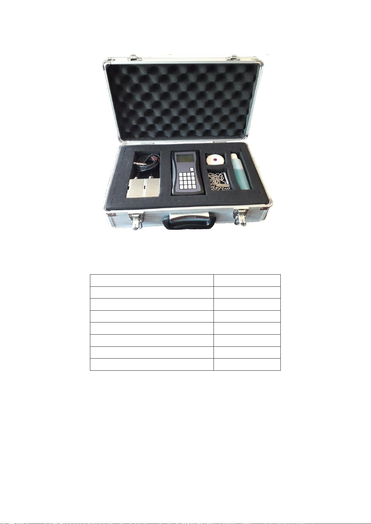
1.2 Packing List
Figure(3) UFM Carry Case and Contents.
Within the UFM carry case, see figure(3) you should find;
Item
Quantity
POCKET-UFM
1
PEEK/Stainless Steel Flow Transducer
2
Wall Thickness (WTG) Probe
Optional
Chain Mounting Clamp
2
Tape Measure
1
Coupling Gel
1
Battery
1
Table(1) Packing List.
If any item on the packing list is missing or has been damaged in transit contact Service, see
Appendix A.

1.3 General Precautions
The content of this manual has been carefully checked and is believed to be accurate.
Sonic Driver Ltd assumes no responsibility for any inaccuracies that may be contained in this
manual.
In no event will Sonic Driver Ltd be liable for direct, indirect, special, incidental or consequential
damages resulting from any defect or omission in this manual, even if we are advised of the
possibility of such damages.
Sonic Driver Ltd reserves the right to make improvements to its manuals, instructions and products
at any time, without notice or obligation. The latest revisions may be found on the company web
site, see appendix A.
The UFM is a precision measuring instrument and should be handled and operated with care;
•Before operating the UFM for the first time read the installation manual and operating
instructions fully.
•Only use the UFM in the way and for the purpose that it is intended.
•Do not subject the UFM to bumps and shocks such as caused by dropping the UFM.
•Keep the UFM and its transducers and probes clean.
•Only use the UFM within its ambient temperature and stated level of Ingress Protection.
•Avoid excessive stress and bending of transducer cables and connectors.
•Avoid striking the clear display window and keypad with sharp objects.
1.4 Cleaning
Wipe the UFM and sensors with tissue or soft cloth after use, remove excess coupling gel.
1.5 Storage
When not is use the UFM and transducers should ideally be cleaned and stored in the carry case
they were supplied in.
1.6 Fitting/Changing Internal Battery
The UFM is powered by a single 9V internal battery. Sonic Driver recommend a high capacity
primary battery of at least 1200mAh be used.
To fit or change the battery slide the cover of the battery compartment in the rear of the UFM, see
figure(4).

Figure(4) Battery compartment.
Lower capacity or use of rechargeable battery will decrease the run time of the UFM.
1.7 Connecting The Flow Transducers
Connect the flow transducers to the Lemo connectors at the top of the UFM, see figure(5).
Figure(5) Flow transducer connection.
Red flow transducer is mounted on the pipe downstream, black flow transducer is mounted
upstream.
When using the WTG probe then connector orientation is not important.

1.8 Mounting The Flow Transducers
Mount the flow transducers on the pipe using the chain clamps supplied, see figure(6). Ensure that
the arrow on the labels (arrowhead and flights) on the flow transducers is pointing in the direction
of flow.
Use coupling gel between the transducers and the pipe to give good ultrasonic contact.
Measure the spacing of the transducers using the tape measure provided, note that spacing is
measured between the front faces of the transducers. Ensure the transducers are facing each other
and aligned axially along the pipe.
Figure(6) Flow transducer mounting, spacing is 25mm between front faces.
In figure(7) and figure(8) the transducers are misaligned and twisted, as a result the UFM will make
poor flow measurements.
Figure(7) Misaligned transducers. Figure(8) Twisted transducers.

When using the WTG probe it is possible to simply hold the probe on the pipe by hand, making
good contact using coupling gel.
1.9 Turning the UFM On
To power on a POCKET-UFM press and hold the On key.
As soon as the UFM is switched on a self-diagnostic program will start. This program fully tests
both the UFM hardware and software.
If an error is detected an error message will be displayed prompting user action. If the error persists
contact customer support, see appendix A.
Error codes and their meanings can be found in the Main Menu under the Diagnostics Menu.
In order to turn the UFM off from the Main Menu press and hold the “</Off” key.
A progress bar decrements to turn the UFM off.
If the “</Off” key is released before the progress bar fully decrements the UFM returns to the
Measurement screen.
If there is no keypad activity in User Interface (UI) mode for 60 seconds then the UFM will
automatically power off. Automatic power off does not apply in Measurement mode.

2.0 Using the Quick Start Sequence
Once powered on the UFM will be in UI mode displaying the Main Menu.
The Main Menu allows the user to select a group of parameters to edit or a meter function;
•Quick Start
•Installation
•System Settings
•Diagnostics
•Load/Save Setups
The Quick Start function takes the user through the minimum sequence of parameters needed to get
the UFM measuring reliably;
•Transducer Type
•Transducer Mounting
•Pipe Diameter
•Pipe Wall Thickness
•Pipe Material
•Liner Material
•Fluid
•Fluid Temperature
Each parameter is described below in the relevant section.
After selecting Transducer Type and Transducer Mounting it is also possible to jump to the end of
the sequence by pressing the Run/Stop key.

2.1 Transducer Menu
This menu allows the user to change transducer settings.
2.1.1 Type
The user is prompted to select the type of sensors mounted on the pipe from a list;
•DS05
•DS10
•DS20
•DS40
•DM10 (Default)
•DM20
•DN40
•Flow Other
•WTG
DM sensors are Sonic Driver standard PEEK/stainless steel design. DN sensors are Sonic Driver
small pipe design. DS sensors are Sonic Driver large pipe design.
If Flow Other is selected then the user will be prompted to enter detailed transducer specific
information.
The ability to select Flow Other is intended for use when using the UFM with special sensors
supplied by Sonic Driver.
Wall Thickness Gauging (WTG) is for use with dual element 5MHz wall thickness probes.
When operating as a wall thickness gauge the user can scroll between 3 display modes by
repeatedly pressing the “Enter” key, the modes are;
•Full display of wall thickness measurement and all measurement diagnostics.
•A-Scan showing the raw received ultrasonic signal.
•Processed signal showing the measured signal corresponding to the wall thickness.
2.1.2 Mounting
The user is prompted to select the sound path in the pipe from a list;
•Auto (Default)
•Z
•V
•N
•W
•5
•6
•7
•8
•9
•10
•11
•12
Selecting Auto means that the UFM determines for itself which sound path to use. Ideally choose a
number of passes that results in a path length in the fluid of 100mm or greater.
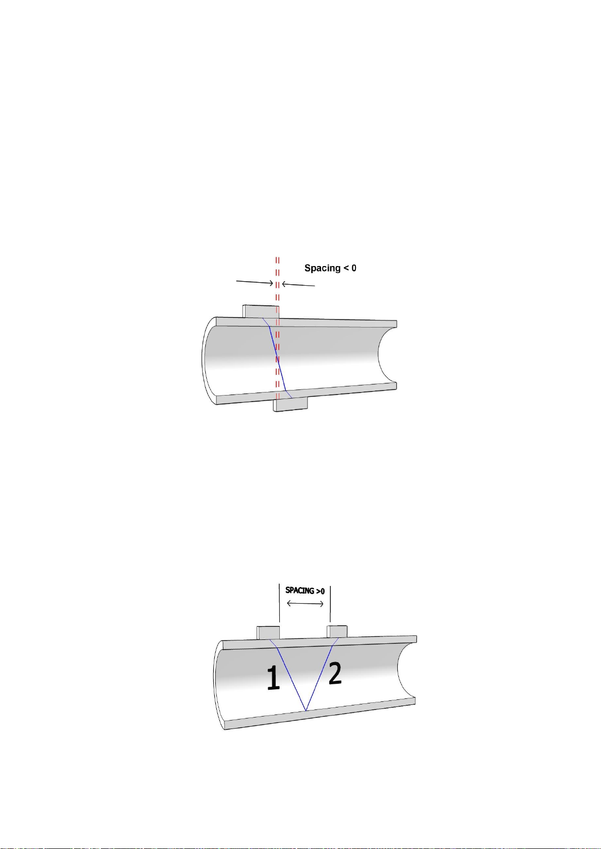
•Z or 1 pass, most common on large diameter pipes, typically 100mm or more in diameter. If
the UFM suggests a negative spacing then this is measured as in figure(9).
Figure(9) Z or 1 pass, demonstrating a negative transducer spacing.
•V or 2 passes, the most commonly used method, this is the simplest to install as both sensors
are on the same side of the pipe, see figure(10).
Figure(10) V or 2 passes.
•N or 3 passes, used on small diameter pipes.
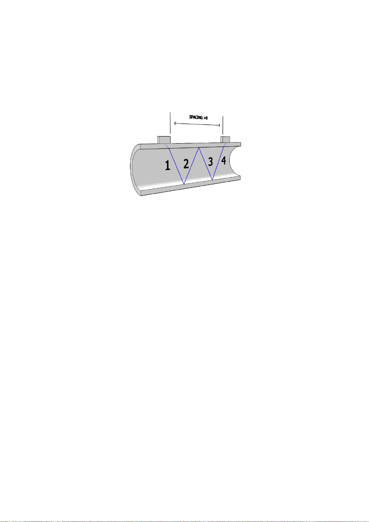
•W or 4 passes, used on the smallest diameter pipes, see figure(11).
Figure(11) W or 4 passes.
•5 to 11 and 12, etc.
It may be that on the smallest diameter pipes then the recommended transducer spacing at 12 passes
is not sufficient to allow the transducers to be coupled on the same side of the pipe, using an even
number of passes as they still touch. In this case it is unavoidable to couple the transducers on
opposite sides of the pipe using an odd number of passes, for example 9 or 11 passes.
Red flow transducer is mounted on the pipe downstream, black flow transducer is mounted
upstream, see figure(5).
When using the WTG probe then connector orientation is not important.

2.2 Pipe Menu
The following parameters allow the user to specify the pipe.
2.2.1 Outer Diameter
The user is prompted to enter a value for the pipe outer diameter. Allowed values are ranged 10.0 to
6500.0mm, default 60.6mm.
2.2.2 Wall Thickness
The user is prompted to enter a value for the pipe wall thickness.Allowed values are ranged 0.5 to
100.0mm, default 3.2mm.
2.2.3 Material
The user can select the pipe material from a list;
•Carbon Steel (Default)
•Stainless 304
•Stainless 316
•Cast Iron
•Ductile Iron
•Copper
•PVC
•Lead
•Nylon
•PE
•Aluminium
•Asbestos
•Fibre Glass
•Other
If Other is selected then the user is prompted to enter the transverse (shear) speed of sound in the
pipe material, see below. Otherwise the transverse speed of sound in the pipe material is read from a
database held in the UFM.
2.2.4 Sound Velocity
Appearance of this parameter is context driven. If the user selected Other from the list of pipe
materials then the user is prompted to enter the transverse speed of sound in the pipe material.
Otherwise the speed of sound in the pipe material is read from a database held in the UFM.
Allowed values are ranged 500 to 7000m/s, default 3206m/s (Carbon Steel).

2.3 Liner Menu
This menu allows the user to change pipe lining settings.
2.3.1 Material
The user can select a pipe liner material from a list;
•None (Default)
•Cement
•Epoxy
•Glass
•PP
•Teflon
•Rubber
•Other
The list allows no liner (None) to be selected.
2.3.2 Sound Velocity
Appearance of this parameter is context driven. If the user selected Other from the list of liner
materials then the user is prompted to enter the transverse speed of sound in the liner material.
Otherwise the speed of sound in the liner material is read from a database held in the UFM.
Allowed values are ranged 500 to 7000m/s, default 0m/s (None).
2.3.3 Thickness
Appearance of this parameter is context driven. If the user selected a liner then the user is prompted
for the thickness of the liner. Allowed values are ranged 0.5 to 100.0mm, default 0.0mm (None).

2.4 Fluid Menu
This menu allows the user to change fluid settings.
2.4.1 Type
The user can select the fluid in the pipe from a list;
•Water (Default)
•Sea Water
•Kerosene
•Petrol
•Fuel Oil
•Crude Oil
•Freon R134a
•Freon R22
•Diesel Oil
•Castor Oil
•F-76 Fuel Oil
•Novec 1230
•Glycol/Water
•Alcohol
•Other
If the user selected Other from the list of fluid types then the user is prompted to enter various other
context driven parameters including; Fluid Sound Velocity, Fluid Kinematic Viscosity and Fluid
Density.
2.4.2 Temperature
The user is prompted to enter the temperature of the fluid in the pipe.Allowed values are ranged -20
to +150 degC, default 18 degC.
Changing Fluid Temperature causes Fluid Sound Velocity, Fluid Kinematic Viscosity, Fluid Density
and Fluid Specific Heat Capacity to be recalculated.

3.0 Sensor Positioning
After completing entry of all parameters in the Quick Start function sequence the user is prompted
to confirm Transducer Type and is then taken to the Sensor Positioning screen.
Using the entered parameters the UFM calculates and gives the required transducer spacing on the
pipe. The screen also displays the number of passes selected by the user or calculated by the UFM if
in Auto Passes mode.
Clamp the transducers on the pipe using the supplied chain clamps and coupling gel, measure the
spacing using the tape measure provided. The user is then presented with a sensor positioning
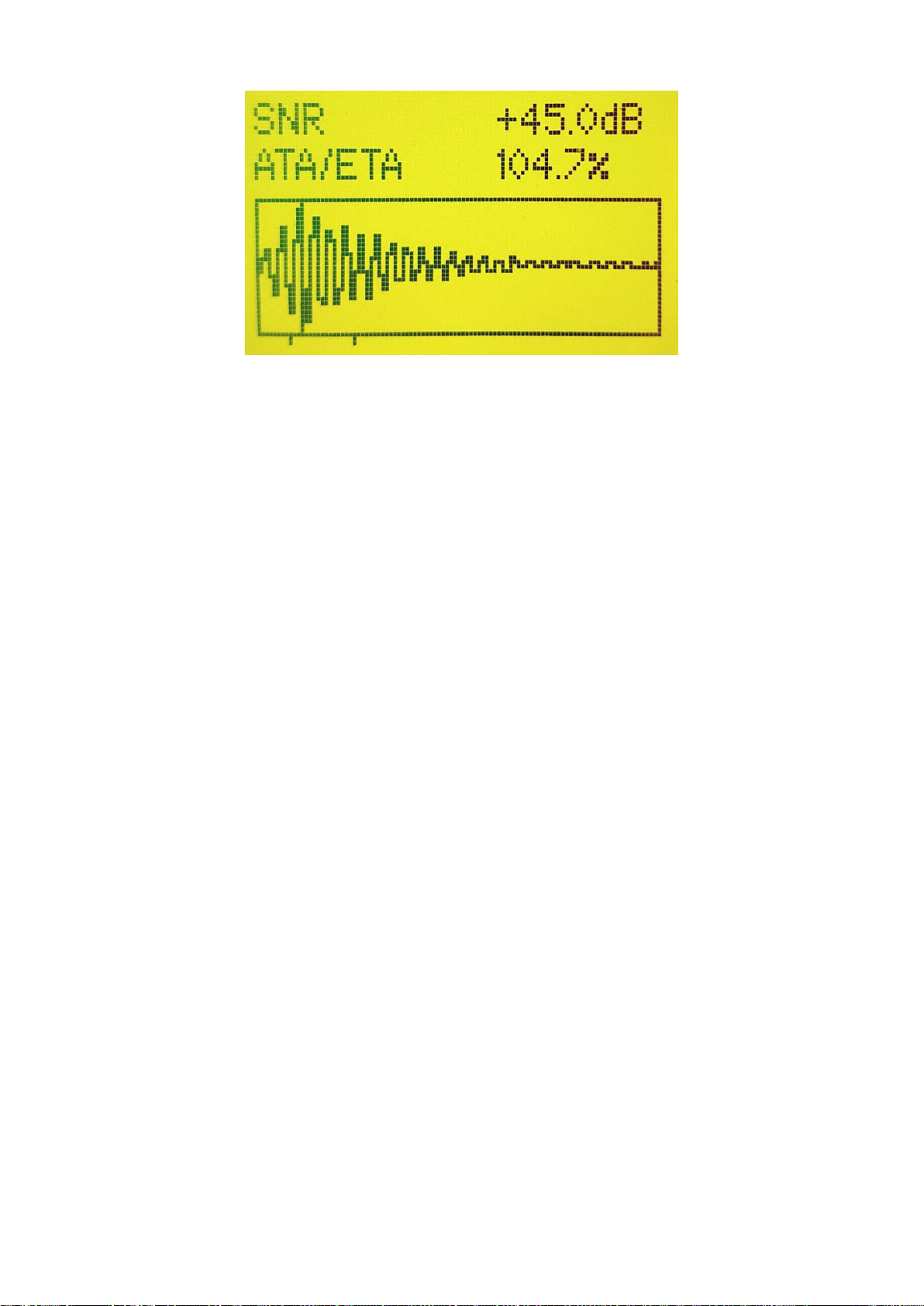
screen showing,
•Graph of received ultrasonic signal
•Signal to Noise Ratio
•ATA/ETA
If the parameters entered are all correct then the graph should appear as in figure(12).
Figure(12) Ideal Sensor Positioning.
However, if the user has an incomplete knowledge of the pipe then the screen may look like
figure(13) or figure(14).
Figure(13) Non-ideal Sensor Positioning, transducers too far apart.
Figure(14) Non-ideal Sensor Positioning, transducers too close together.
In figure(13) the received signal is too far to the right, the user should slide the transducers closer
together.
In figure(14) the received signal is too far to the left, the user should slide the transducers further
apart.
The most common cause of an incomplete or incorrect spacing is a lack of knowledge about the
pipe wall thickness.
As long as the vertical line acting as arrival marker is between the 2 guide marks, resulting in an
ATE/ETA value between 97 and 103% then the UFM will measure accurately. It is acceptable to
reposition the transducers to adjust their spacing by +/- 5 mm to optimise the positioning screen, the
arrival marker will move on the screen accordingly.
SNR should peak and be above 24 dB.
3.1 Optimising Transducer Mounting Location
For the best results ensure that,
•Ideally the transducers are mounted on bare pipe material, for metal pipes this should be
metal free from dust, rust and paint.
•Consider a location away from internal corrosion, sediment and streams of entrained air, do
not mount the transducers top to bottom on the pipe, mount at 2 or 10 o'clock.
•Avoid mounting the transducers either on or opposite axial welds along the pipe.
•Ensure the transducers are aligned axially along the pipe.
•Mount the transducers away from bends, valves and other inserted instrumentation.
•Observe were practical the advised upstream and downstream straight sections, see below,
figure(15).
•Ensure the pipe will always be full at the point of installation, ideally mount the transducers
at a low point in the system.
•If mounting the transducers on a vertical pipe section ensure the flow direction is upwards in
the section.
•Composite pipes can have de-laminations in their wall thickness, this type of pipe is
notoriously bad when installing a UFM.
•Ensure the temperature at the transducer location is within the transducers rated range.

•Ideally the fluid should be free of particulates and bubbles, in the limit then an alternative
method such as Doppler flow measurement may be required.
•Pipe linings that are not bonded properly or are not conductive of ultrasound (rubber) will
cause measurement problems.
•Porous pipes, such as concrete can cause measurement problems.
•Using information from Standard Pipe Tables can be inaccurate, it is always best to measure
the pipe outer diameter and wall thickness.
•No matter how accurate the meter is at making a velocity measurement, an inaccurate
knowledge of the internal cross-sectional area of the pipe will lead to inaccuracy in the
conversion to volumetric flow rate.
3.2 Upstream and Downstream Pipe Runs
Ideally the UFM transducers should be installed on as long a section of straight pipe as is possible,
see figure(15).
Figure(15) Upstream and downstream pipe lengths.
Considering a pipe with an outer diameter of D then if possible ensure at least 10D upstream
distance between the transducers and a bend in the pipework.
In the case of an upstream Valve then if possible ensure at least 20D upstream.
In the case of an upstream Pump then if possible ensure at least 30D upstream.
In all cases ideally ensure 5D downstream exists before a bend or obstruction in the pipework.
3.3 Transducer Mounting
Locate an optimum position on the pipe following the advice above.
Use Coupling gel. Apply adequate couplant and ensure no gap exists between the transducer and the
pipe surface.
Banding or clamping is required to keep the transducers in place. It is recommended to use the
Table of contents
Other Sonic Driver Measuring Instrument manuals


