Erma Electronic SSI 9006 User manual
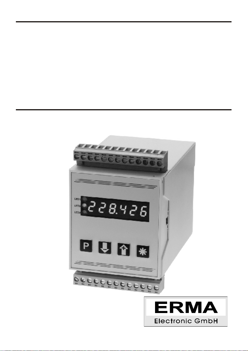
SSI 9006
Digital Panel Meter
for Absolute Encoders with Synchron-Serial-Interface
Instruction Manual

Warranty
For delivered products our "Allgemeine Lieferungs- und Zahlungsbedingungen" are effective. In no event
we or our suppliers shall be liable for any other damages whatsoever (including, without limitation, dama-
ges for loss of business profits, business interruption or other pecuniary loss) arising out of or inability to
use this product.
All our products are warranted against defective material and workmanship for a period of two (2) years
fromdateofdelivery.Ifitisnecessarytoreturntheproduct, thesenderisresponsibleforshippingcharges,
freight,insurance andproperpackaging toprevent breakagein transit.The warrantydoes notapplyto de-
fectsresultingfromactionofthebuyer,suchas mishandling,improperinterfacing,operationoutsideofde-
sign limits, improper repair or unauthorized modification.
Trademarks
All trademarks that are named or portrayed in the text are registered trademarks of its owner.

CONTENTS
1. Description ...........................5
2. Safety instructions .......................6
2.1. Symbol explanation ....................6
3. Mounting ............................7
3.1. Place of operation .....................7
3.2. Mounting of signal converter................7
4. Electrical connections .....................8
4.1. General instructions ....................8
4.2. Hints against noisy environment..............8
4.3. Connection and pin assignment..............9
4.4. Connection of absolute encoder..............10
4.5. Connection of digital user inputs .............10
4.6. Connection of alarm outputs (relay) ............10
4.7. Connection of RS 485 interface ..............11
4.8. Connection of power supply voltage............11
4.8.1. Supply voltage 18 ... 36 V DC ...........11
5. Startup procedure .......................11
6. Pushbuttons- and LED-functions ...............12
6.1. Function of buttons and LEDs ...............12
7. Modes ..............................13
7.1. Operation level.......................13
7.2. Access-code level .....................14
7.3. Programming level.....................15
8. Procedure of programming ..................16
8.1. Changing or controlling parameters ............16
8.2. Overview of the programming levels ...........17
8.3. Programming level for configuration P-00.........18
8.3.1. Scaling the display range .............20
8.4. Programming level of alarms P-02 ............21
8.4.1. Alarm output functions...............23
ERMA-Electronic GmbH 3

8.4.2. Alarm high setpoint ................24
8.4.3. Alarm low setpoint.................24
8.5. Programming level of serial interface P-04 ........25
8.5.1. Transmission-Mode ................25
8.6. Programming quick reference ...............26
9. Software functions .......................28
9.1. Master/Slave-Mode ....................28
9.2. Zero point adjustment ...................28
9.2.1. Zero point adjustment by pressing button.....28
9.2.2. Zero point adjustment by offset value .......29
9.3. Incremental measurement.................30
9.4. Direction of rotation ....................30
9.5. MIN/MAX value detection .................30
9.6. Hold function........................31
9.7. Removing bits of the encoder value............31
9.8. Display test ........................33
9.9. Main reset .........................33
10. Error codes ...........................33
10.1. Encoder not connected “Err01" ..............33
10.2. Waiting for data input “Err02" ...............33
10.3. External clock frequency too high “ERR03" ........33
11. Technical Specifications....................34
11.1. Electrical datas.......................34
11.2. Mechanical datas .....................35
11.3. Environmental conditions .................35
12. Ordering Information......................35
13. Notes ..............................36
4ERMA-Electronic GmbH
Stand : 06.02.2009
ssi9006_man_en.vp
All details are subject to change

1. Description
The digital converter Model SSI 9006 is an instrument to convert datas of absolute
encoders with Synchronous-Serial-Interface (SSI) in an analog output signal. Si-
multaneous, it can carried out an alarm point controlling.
Standard hardware
•Four relay alarm outputs
•two programmable digital input channels
•three programmable pushbuttons
Standard software
•Encoder adjustments
•Adjustable for encoder with 9-32 bits
•Bit programming for fir-tree data format
•Scaling factor
•Zero point adjustment
•Direction of rotation
•Offset value
•Incremental measurement
•Display test and display hold (Latch)
•MIN/MAX value detection
•Auto-Reset for MIN/MAX value
•Set point editing during normal measurementFollowing options are available
Optional
•RS485 interface
ERMA-Electronic GmbH 5
1. Description

2. Safety instructions
This instrument is produced in accordance with Class II of IEC 348 and VDE 0411.
Whendeliveredtheinstrumenthasbeentestedtomeetallfunctionsdescribed.Befo-
re installing the instrument please read the mounting and servicing instructions.
Wehave noliabilityorresponsibilitytocustomeroranyotherpersonorentitywithre-
spect to any liability, loss or damage caused or alleged to be caused directly or
indirectly by equipment or software sold or furnished by us. Read the installation in-
struction carefully. No liability will be assumed for any damage caused by improper
installation.
Inspect the instrument module carton for obvious damage. Be shure there are no
shipping and handing damages on the module before processing. Do not apply po-
wer to the instrument if it has been damaged.
ERMA’swarrantydoesnotapplytodefectsresultingfromactionofthebuyer,suchas
mishandling,improperinterfacing,operationoutsideofdesignlimits,improperrepair
or unauthorized modifications.
2.1. Symbol explanation
Caution: Will be used at dangerous for life and health !
Attention: Will cause damage
Instruction: If not noticed, trouble may occur
Tip: Useful hints for better operation
6ERMA-Electronic GmbH
2. Safety instructions
Caution Attention Instruction Tip
3. Mounting
3.1. Place of operation
Attentionmustbepayedtotheprotectionagainst humidity,dustandhightemperatu-
res at the place of operation.
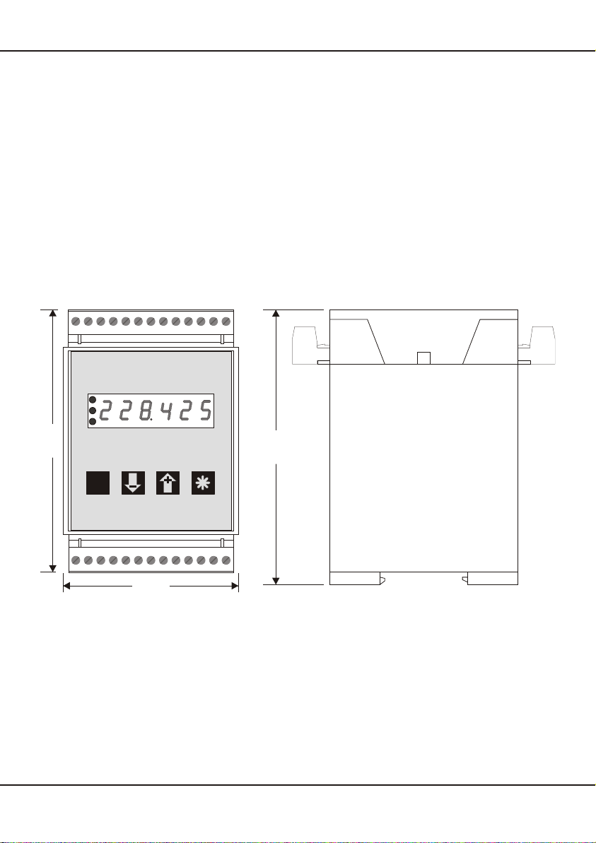
3.2. Mounting of signal converter
•through simple snap up at 35 mm rail (DIN EN 50022)
ERMA-Electronic GmbH 7
3. Mounting
105
70
110
PP
LED3LED3
LED2LED2
LED1LED1
ERMA-METER

4. Electrical connections
4.1. General instructions
•It is forbidden to plug or unplug connectors with voltage applied
•Attachinputandoutputwirestothe connectorsonlywithoutvoltages
applied
•Cords must be provided with sleeves
•Attention must be paid that the power supply voltage applied will
agree with voltage noticed at the name plate.
•The instrument has no power-on switch, so it will be in operation as
soon as the power is connected.
4.2. Hints against noisy environment
All inputs and outputs are protected against noisy environment and high voltage
spikes. Nevertheless the location should be selected to ensure that no capacitive or
inductiveinterferencecanhaveaneffectontheinstrumentortheconnectionlines.
It is advisable:
•To use shielded cables.
•The wiring of shields and ground (0V) should be star-shaped.
•Thedistancetointerferencesourcesshouldbeaslongaspossible.If
necessary,protectivescreenormetalenclosuresmustbeprovided.
•Coils of relays must be supplied with filters.
•Parallel wiring of input signals and AC power lines should be avoi-
ded.
8ERMA-Electronic GmbH
4. Electrical connections

4.3. Connection and pin assignment
All inputs and outputs are connectors, designed as plug-in screw terminals.
Pin assignment:
1Power supply DC (+) 14 SSI-Signalinput, Clock (+)
2 Power supply DC (-) 15 SSI-Signalinput, Clock (-)
3Ground connection 16 SSI-Signalinput, Data (+)
4Option RS485, A (+) 17 SSI-Signalinput, Data (-)
5Option RS485, B (-) 18 SSI-Signalinput, GND (0 V)
6/7 Alarm (relay) output 4 19 Ground connection
8/9 Alarm (relay) output 3 24 Digital user input 1
10/11 Alarm (relay) output 1 25 Digital user input 2
12/13 Alarm (relay) output 2 26 Digital GND
ERMA-Electronic GmbH 9
4. Electrical connections
PP
LED3LED3
LED2LED2
LED1LED1
ERMA-METER
1122557788996644331111 1212
1010 1313
1414
15152626 2525 2424 2323 2222 2121 2020 1919 1818 1717 1616
+-alarm4 alarm3 alarm1 alarm2
signal input
digital
inputs
RS 485
n.c.
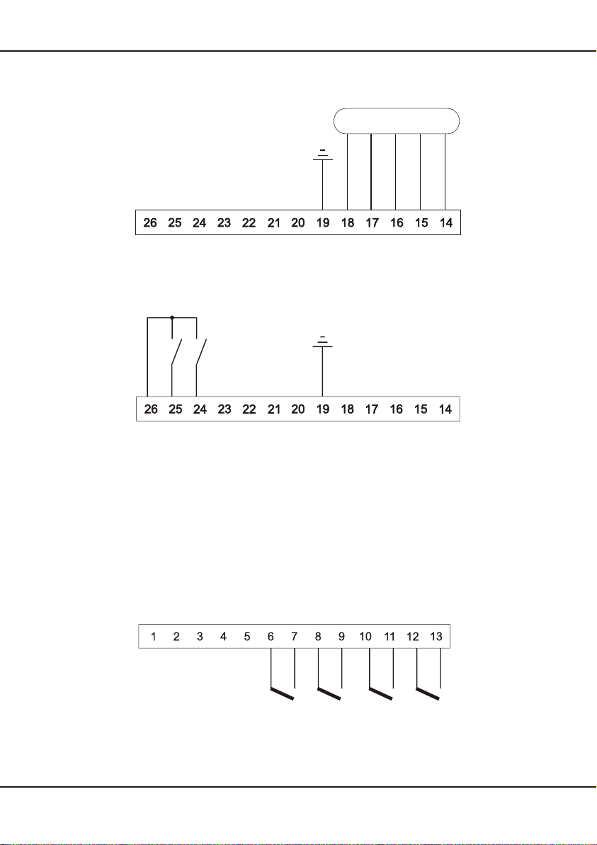
4.4. Connection of absolute encoder
4.5. Connection of digital user inputs
Digital input 1
•active => Connecting Screw Terminal 24 to 26
•Connecting to Ground, low active
Digital input 2
•active => Connecting Screw Terminal 25 to 26
•Connecting to Ground, low-active
4.6. Connection of alarm outputs (relay)
10 ERMA-Electronic GmbH
4. Electrical connections
alarm 1 alarm 2alarm 4 alarm 3
Encoder
Clock -
Clock +
Data+
Data-
(GND)

4.7. Connection of RS 485 interface
4.8. Connection of power supply voltage
4.8.1. Supply voltage 18 ... 36 V DC
5. Startup procedure
Attentionmustbepaidthatthepowersupplyvoltageappliedwillagreewith
the voltage noticed at the name plate. Switch the power supply on (supply
voltage applied to screw terminal 1 and 2). After about 2 seconds the dis-
play will indicate the applied input signal.
Whendelivered,theinstrumentisprogrammedwithastandardconfigurati-
on (default values). By programming the customer can change the stan-
dard configuration according to his measuring task.
Attention ! When the instrument is built in a machine and the customer
wantstochange the configuration,attentionmustbepaid, thatnodamage
will occur to the machine!
ERMA-Electronic GmbH 11
5. Startup procedure
+-
A(+)
B(-) A
B
A
B
1122557788996644331111 1212
1010 1313
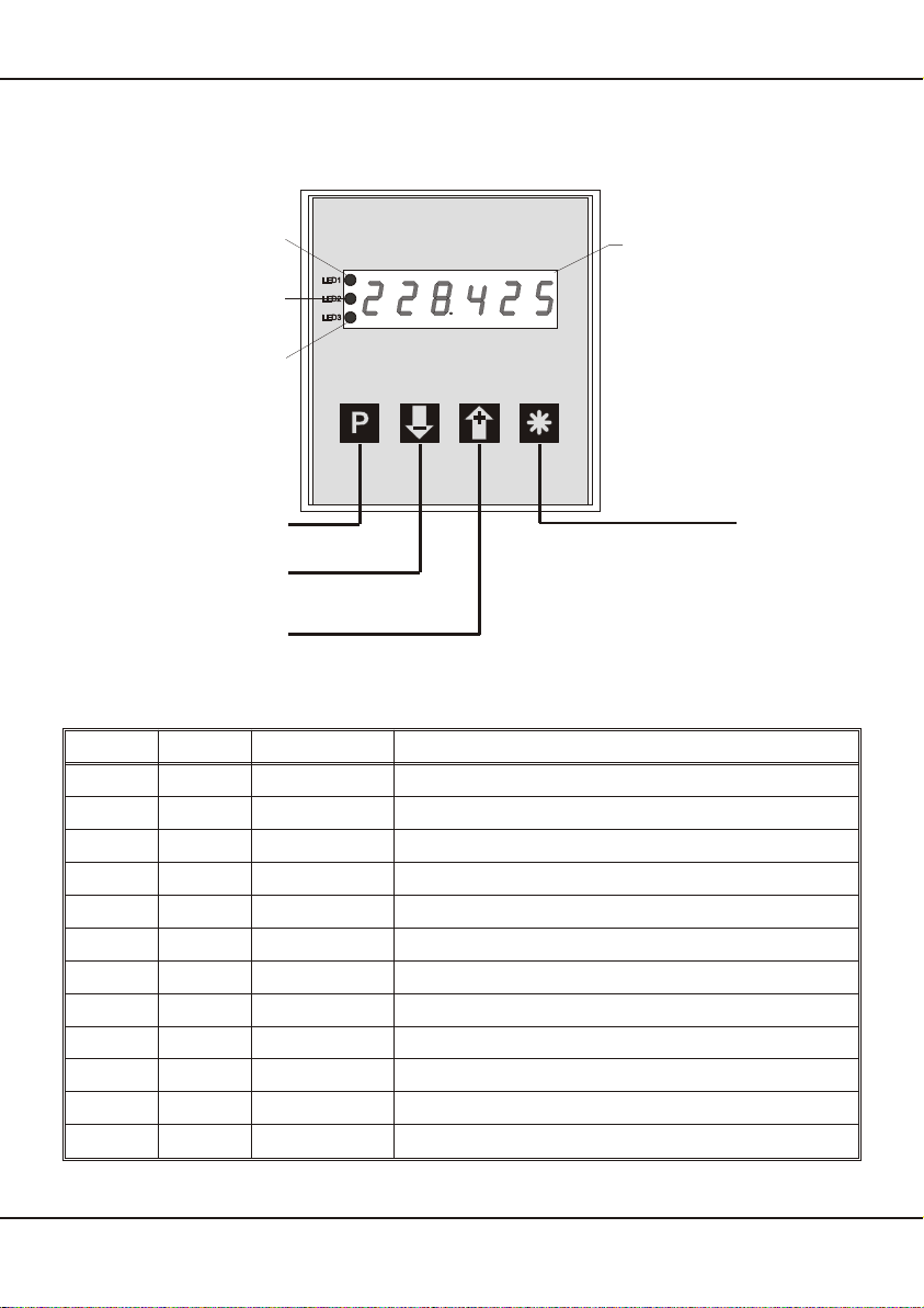
6. Pushbuttons- and LED-functions
Therearefourpushbuttonsinthefront.Thesepushbuttonscanhavedifferentfuncti-
ons.Thefunctionsofthepushbuttonscanbeusedforprogrammingandforservice.
6.1. Function of buttons and LEDs
LED 1 LED 2 LED 3 Description
xxoff encoder- or hold value is displayed
xxred MIN value is displayed
xxgreen MAX value is displayed
xxgreen/flashs programming mode is activated
xoff xalarm 2 is not activated
xlights x alarm 2 is activated
xflashs off alarm point 2 is displayed
xflashs green/flashs alarm point 2 is changed
off xxalarm 1 is not activated
lights x x alarm 1 is activated
flashs xoff alarm point 1 is displayed
flashs xgreen/flashs alarm point 1 is changed
x = state of the LED is not considered
12 ERMA-Electronic GmbH
6. Pushbuttons- and LED-functions
ERMA-METER
6 decades display
LED2
LED1
LED3
programming button function button
button "-" / alarm 1 / alarm 2
direct input-, max- ,min-
or hold value
button "+" / alarm 1 / alarm 2
direct input-, max- ,min-
or hold value
7. Modes
Theoperationandtheprogrammingofthepanelmeterisorganizedinseveralstates:
•Operation level
•Access-code level
•Programm level
7.1. Operation level
In the state “operation level” the normal functions of the instrument are activated. A
normal measurement cycle looks like below:
•Read the value of encoder, calculate and display
•Evaluate the digital inputs
•Alarm outputs
•Analog output
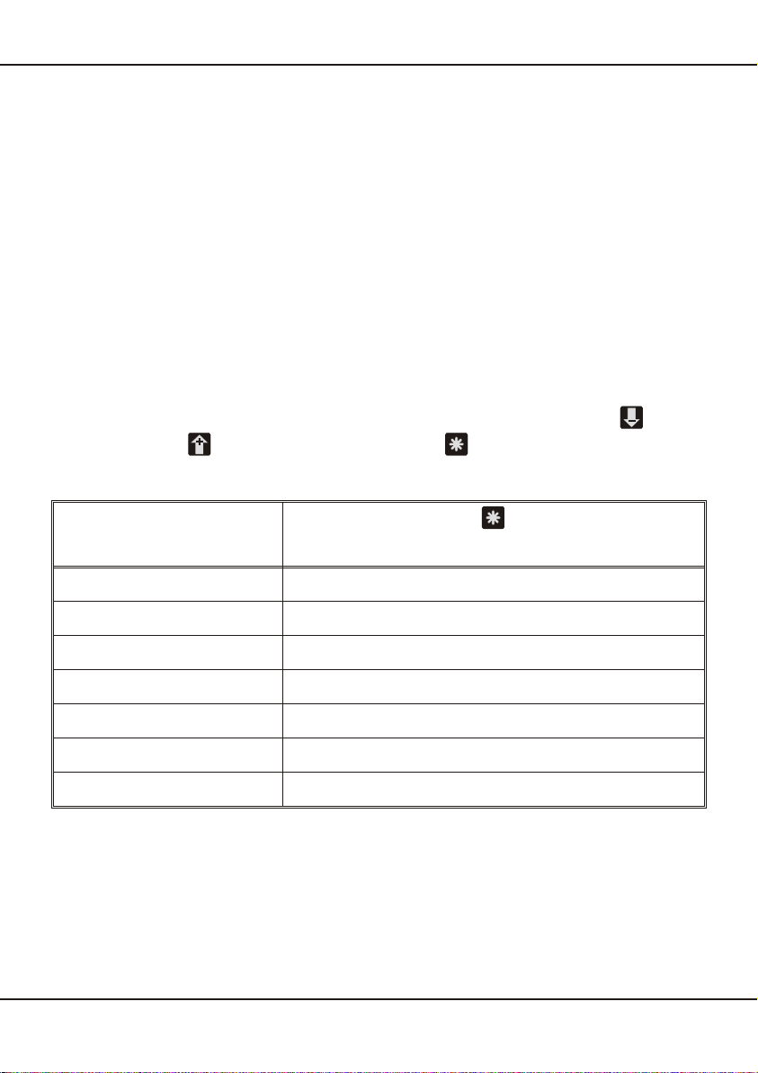
Dependent on the programming of the parameter 0-14 (function of key ), 0-15
(function of key ) and 0-13 (function of key ), following key-functions are
available in the operation level.
Parameter 0-13
Function of pushbutton “*” By pressing
0No function
1Reset the MIN/MAX value
2Taring
3Clear tara value
4Incremental measurement
5Manual reset of alarms
6start single serial transmission
ERMA-Electronic GmbH 13
7. Modes
Parameter 0-14
Function of pushbutton “-” By pressing Pressing during 3 sec.
0No function -
1Display value of encoder -
2Display MAX value -
3Display MIN value -
4Display hold value -
5Display alarm point 1 Change alarm point 1
6Display alarm point 2 Change alarm point 2
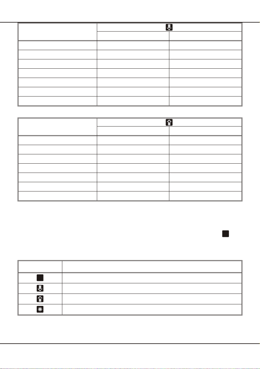
Parameter 0-15
Function of pushbutton “+” By pressing Pressing during 3 sec.
0No function -
1Display value of encoder -
2Display MAX value -
3Display MIN value -
4Display hold value -
5Display alarm point 1 Change alarm point 1
6Display alarm point 2 Change alarm point 2
7.2. Access-code level
The state “access-code level” becomes active by pressing the pushbutton du-
ring the state “operation level”. The display shows “c000". During the state ”access-
code level" the normal functions of the instrument are active.
pushbutton Function
Confirm of the displayed access-code
Increase the access-code
Decrease the access-code
Programmed function
14 ERMA-Electronic GmbH
7. Modes
PP
P
P
7.3. Programming level
The state “programm level” becomes active by entering the right access-code. The
access-code must be confirm by pressing the pushbutton . The programming is
organized in following steps:
•Selection of a programming level
•Selection of a parameter
•Change of the selected parameter
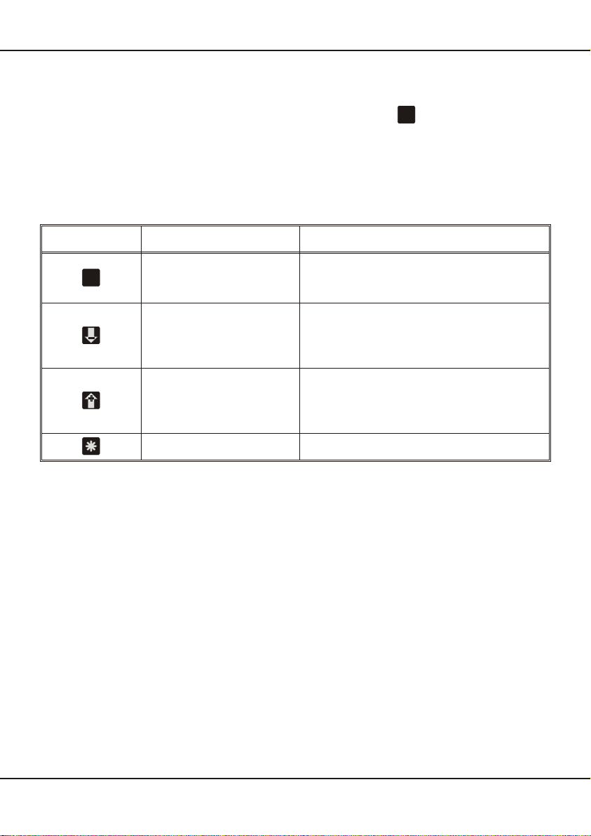
Pushbutton Press Pressing during 3 sec.
Selection of
- Programming level
- Parameter -
Decrease of
- Programming level
- Number of parameter
- Value of parameter
-
Increase of
- Programming level
- Number of parameter
- Value of parameter
-
-Break the programming routine
ERMA-Electronic GmbH 15
7. Modes
PP
P
P

8. Procedure of programming
The procedure of programming is organized in several different steps.
Access to the selection of the programming levels
•Pressing pushbutton => access-code enter is active
•The display shows “c000"
•Changing the access-code by pressing the pushbutton or and confirm
the changed access-code by pressing the pushbutton
If the entered access-code is not correct, the instrument will jump back to the state
“operation level”.
8.1. Changing or controlling parameters
Activating the programming routine
•Pressing pushbutton
•LED 3 flashs green
•The display shows “c000"
•Changing the access-code by pressing the pushbutton or
•Confirm access-code by pressing the pushbutton
•The display shows “P-00"
Leaving the programming routine
•Pressing the pushbutton or until the display shows “PEnd”
•Confirm the display “PEnd” by pressing the pushbutton
•LED 3 is off
•The active state of the panel meter is “operation level”
Selection of the programming level
•Selecting the programming level by pressing the pushbutton or
•Confirm the programming level by pressing the pushbutton
•Thedisplayshowsthenumberoftheparameteroftheselectedprogramminglevel
For example: “0-00" => parameter 0 of the programming level 0
For example: ”2-00" => parameter 0 of the programming level 2
16 ERMA-Electronic GmbH
8. Procedure of programming
PP
P
P
P
P
P
P
P
P
P
P

Leaving the programming level
•Pressing the pushbutton or until the display shows “xEnd”
For example: “0End” => leaving programming level 0
For example: “2End” => leaving programming level 2
•Confirm the display “xEnd” by pressing the pushbutton
•The display shows the programming level
For example: “P-00" => for programming level 0
For example: ”P-02" => for programming level 2
Selection of the parameter
•Selection the parameter by pressing the pushbutton or
•Confirm the parameter by pressing the pushbutton
•The display shows the last programmed value of the selected parameter
Change and controll the selected parameter
•Change the value of the parameter by pressing the pushbutton or
•Confirm the value of the parameter by pressing the pushbutton
•The display shows the programming level and the number of the parameter
For example: “0-05" => parameter number 5 of programming level 0
For example: ”2-08" => parameter number 8 of programming level 2
8.2. Overview of the programming levels
The parameters of the panel meter are organized in different programming levels.
P-00: Programming level for configuration of the panel meter
The configuration is used to adapt the absolute encoder and the panel meter.
P-02: Programming level for the alarms
This programming level is used to programm all settings for the alarm outputs.
P-04: Programming level of the serial interface
This programming level is used to programm the address and baud rate of the serial
interface.
ERMA-Electronic GmbH 17
8. Procedure of programming
PP
P
P
P
P

8.3. Programming level for configuration P-00
Param. Description Setting range Default
value
0-00 Resolution (Bits) 09 .. 32 12
0-01 Output code
0 -> Gray
1 -> Binary 0 .. 1 0
0-02 Master/Slave-Mode
0 -> Instrument = Master
1 -> Instrument = Slave 0 .. 1 0
0-03
Clock for Master-Mode
0 -> Frequency = 200 kHz
1 -> Frequency = 100 kHz
2 -> Frequency = 500 kHz
3 -> Frequency = 1 MHz
0 .. 3 0
0-04 Zero adjustment
0 -> Zero adjustment without sign
1 -> Zero adjustment with ± display 0 .. 1 0
0-05 Counting direction
0 -> increasing clockwise rotation
1 -> increasing anticlockwise rotation 0 .. 1 0
0-06 Scalingfactor 0.00001 .. 9.99999 1.00000
0-07 Offset value -99999 .. 999999 0
0-08
Programmable decimal points
0 -> XXXXXX
1 -> XXXXX.X
2 -> XXXX.XX
3 -> XXX.XXX
4 -> XX.XXXX
5 -> X.XXXXX
0 .. 5 0
0-09
Data source of the display
0 -> Encoder value
1 -> MAX value
2 -> MIN value
3 -> Hold value
0 .. 3 0
0-10 Reset time of the MIN/MAX value
0 -> No automatically reset
X -> Reset time in seconds 0 .. 100 0
18 ERMA-Electronic GmbH
8. Procedure of programming

Param. Description Setting range Default
value
0-11
Function of digital user input 1
0 -> No function
1 -> Reset MIN/MAX value
2 -> Taring of encoder
3 -> Clear tara value of encoder
4 -> Incremental measurement
0 .. 11 0
0-11
continue of 0-11:
Function of digital input 1
5 -> Manual reset of alarms
6 -> Hold function
7 -> Display test
8 -> Display value of encoder
9 -> Display MAX value
10 -> Display MIN value
11 -> start single serial transmission
0 .. 11 0
0-12
Function of digital user input 2
0 -> No function
1 -> Reset MIN/MAX value
2 -> Taring of encoder
3 -> Clear tara value of encoder
4 -> Incremental measurement
5 -> Manual reset of alarms
6 -> Hold function
7 -> Display test
8 -> Display value of encoder
9 -> Display MAX value
10 -> Display MIN value
11 -> start single serial transmission
0 .. 11 0
0-13
Function of push button “*”
0 -> No function
1 -> Reset MIN/MAX value
2 -> Taring of encoder
3 -> Clear tara value of encoder
4 -> Incremental measurement
5 -> Manual reset of alarm
6 -> start single serial transmission
0 .. 6 0
0-14
Function of pushbutton “-”
0 -> No function
1 -> Display value of encoder
2 -> Display MAX value
3 -> Display MIN value
4 -> Display hold value
5 -> Display/change alarm point 1
6 -> Display/change alarm point 2
0 .. 6 0
ERMA-Electronic GmbH 19
8. Procedure of programming

Param. Description Setting range Default
value
0-15
Function of pushbutton “+”
0 -> No function
1 -> Display value of encoder
2 -> Display MAX value
3 -> Display MIN value
4 -> Display hold value
5 -> Display/change alarm point 1
6 -> Display/change alarm point 2
0 .. 6 0
0-16 Number of removed most significant bits
from the encoder data (MSBs) 0 .. 31 0
0-17 Number of removed least significant bits
from the encoder data (LSBs) 0 .. 31 0
0-18 Access-code 0 .. 999 0
0End Leaving programming level 0
8.3.1. Scaling the display range
Thescalingofthedisplayrangeismatchedbyusingascaling-factorandanoffsetva-
lue. The calculation of the display value looks like below:
The overflow or underflow becomes active, if the displayed value is greater than
999999 or smaller than -99999.
•When overflow is activ the display shows “nnnnnn”
•When underflow is active the display shows “uuuuuu”
20 ERMA-Electronic GmbH
8. Procedure of programming
Display = (Enc_value - Zero_adjustmet) x Sca_faktor + Offset value
Table of contents
Other Erma Electronic Measuring Instrument manuals


Popular Measuring Instrument manuals by other brands

P3 International
P3 International E9350 Specifications

Campbell
Campbell LI200R instruction manual

GE
GE SimpliNano Original instructions

RS PRO
RS PRO RSST-2000 Series quick start guide

Keysight
Keysight 53147A Operating and Programming Guide

DENT Instruments
DENT Instruments PowerScout 3 HD quick start guide

ENMET
ENMET MedAir 2200 Operation and maintenance manual

Fox Thermal
Fox Thermal FT3 manual

Metek
Metek Tono-Pen AVIA user guide

Schaller Messtechnik
Schaller Messtechnik humimeter FS1 operating manual

Apera Instruments
Apera Instruments 950 Series user manual

Keysight Technologies
Keysight Technologies N5244/5B Service guide


