Erma Electronic SSI 3020 User manual

SSI 3020
Digital Panel Meter
for Absolute Encoders with Synchron-Serial-Interface
Instruction Manual

Warranty
For delivered products our "Allgemeine Lieferungs- und Zahlungsbedingungen" are effective. In no event
we or our suppliers shall be liable for any other damages whatsoever (including, without limitation, dama-
ges for loss of business profits, business interruption or other pecuniary loss) arising out of or inability to
use this product.
All our products are warranted against defective material and workmanship for a period of two (2) years
fromdateofdelivery.Ifitisnecessarytoreturntheproduct, thesenderisresponsibleforshippingcharges,
freight,insurance andproperpackagingtopreventbreakageintransit.The warrantydoesnotapplytode-
fectsresultingfromactionofthebuyer,suchas mishandling,improperinterfacing,operationoutsideofde-
sign limits, improper repair or unauthorized modification.
Trademarks
All trademarks that are named or portrayed in the text are registered trademarks of its owner. The tra-
demarks are recognized by ERMA-Electronic.

CONTENTS
1. Description ...........................5
2. Safety instructions .......................5
2.1. Symbol explanation ....................5
3. Mounting ............................6
3.1. Place of operation .....................6
3.2. Mounting of digital panel meter ..............6
3.2.1. Housing for switch board .............6
4. Electrical connections .....................7
4.1. General instructions ....................7
4.2. Hints against noisy environment..............7
4.3. Connection and pin assignment..............7
4.4. Connection of absolute encoder..............8
4.5. Connection of power supply voltage............8
5. Startup Procedure .......................8
6. Pushbuttons- and LED-functions ...............9
6.1. Function of buttons and LEDs ...............9
7. Modes ..............................10
7.1. Operation level.......................10
7.2. Access-code level .....................10
7.3. Programming level.....................11
8. Procedure of programming ..................12
8.1. Changing or controlling parameters ............12
8.2. Overview of the programming levels ...........13
8.3. Programming level for configuration P-00.........14
8.4. Scaling the display range .................15
8.5. Programming quick reference ...............15
9. Software functions .......................16
9.1. Master/Slave-Mode ....................16
9.2. Zero point adjustment ...................16
ERMA-Electronic GmbH 3

9.2.1. Zero point adjustment by pressing button.....16
9.2.2. Zero point adjustment by offset value .......18
9.3. Directions of rotations ...................18
9.4. Main reset .........................18
10. Error codes ...........................19
10.1. Encoder not connected “Err01" ..............19
10.2. Waiting for data input “Err02" ...............19
10.3. External clock frequency too high “Err03".........19
11. Technical Specifications....................20
11.1. Electrical datas.......................20
11.2. Mechanical datas .....................20
11.3. Environmental conditions .................21
12. Ordering Information......................21
13. Notes ..............................22
4ERMA-Electronic GmbH
Stand : 28.07.2004
SSI3020A.VP
Technical subjects to change

1. Description
ThedigitalpanelmeterModelSSI3020isaninstrumentfordisplayingandcontrolling
absolute encoders with Synchronous-Serial-Interface (SSI)
Standard functions
•Zero point adjustment
•Offset value
•Scaling factor
•Master/slave
2. Safety instructions
This instrument is produced in accordance with Class II of IEC 348 and VDE 0411.
Whendeliveredtheinstrumenthasbeentestedtomeetallfunctionsdescribed.Befo-
re installing the instrument please read the mounting and servicing instructions.
Wehavenoliabilityorresponsibilitytocustomeroranyotherpersonorentitywithre-
spect to any liability, loss or damage caused or alleged to be caused directly or
indirectly by equipment or software sold or furnished by us. Read the installation in-
struction carefully. No liability will be assumed for any damage caused by improper
installation.
Inspect the instrument module carton for obvious damage. Be shure there are no
shipping and handing damages on the module before processing. Do not apply po-
wer to the instrument if it has been damaged.
ERMA’swarrantydoesnotapplytodefectsresultingfromactionofthebuyer,suchas
mishandling,improperinterfacing,operationoutsideofdesignlimits,improperrepair
or unauthorized modifications.
2.1. Symbol explanation
Caution: Will be used at dangerous for life and health !
Attention: Will cause damage
Instruction: If not noticed, trouble may occur
Tip: Useful hints for better operation
ERMA-Electronic GmbH 5
1. Description
Caution Attention Instruction Tip

3. Mounting
3.1. Place of operation
Attentionmustbepayedtothe protectionagainsthumidity,dustandhightemperatu-
res at the place of operation.
3.2. Mounting of digital panel meter
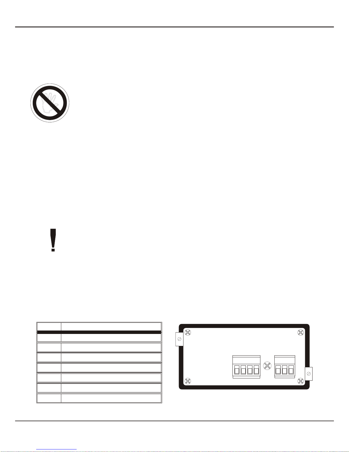
3.2.1. Housing for switch board
•Insertthecaseintothepanelcutout(accordingtoDIN43700:92+0,8x45+0,6 mm)
•Tighten the screws alternately, using enough pressure to get good retention and
sealing at the panel.
6ERMA-Electronic GmbH
3. Mounting
+0,8+0,8
+0,6+0,6
Schalttafelausschnitt
DIN 43700
Schalttafelausschnitt
DIN 43700
ERMA-METER
PP
LED1
LED2
LED3
mm
96,0
42,0
89,6
15,0 55,5 8
45,0 48,0
92,0
4. Electrical connections
4.1. General instructions
•It is forbidden to plug or unplug connectors with voltage applied
•Attach input and output wires to the connectors only without voltages
applied
•Cords must be provided with sleeves
•Attentionmustbepaidthatthepowersupplyvoltageapplied will agree
with voltage noticed at the name plate.
•The instrument has no power-on switch, so it will be in operation as
soon as the power is connected.
4.2. Hints against noisy environment
All inputs and outputs are protected against noisy environment and high voltage
spikes. Nevertheless the location should be selected to ensure that no capacitive or
inductiveinterferencecanhaveaneffectontheinstrumentortheconnectionlines.
It is advisable:
•To use shielded cables.
•The wiring of shields and ground (0V) should be star-shaped.
•The distance to interference sources should be as long as possible. If
necessary, protective screen or metal enclosures must be provided.
•Coils of relays must be supplied with filters.
•ParallelwiringofinputsignalsandACpowerlinesshouldbeavoided.
4.3. Connection and pin assignment
All inputs and outputs are connectors, designed as plug-in screw terminals.
Pin assignment:
Pin Discription
1SSI clock input +
2SSI clock input -
3SSI data input +
4 SSI data input -
9GND
10 Power supply -
11 Power supply +
ERMA-Electronic GmbH 7
4. Electrical connections
910 1123
14
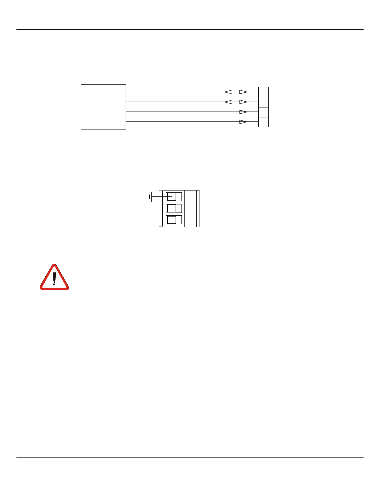
4.4. Connection of absolute encoder
4.5. Connection of power supply voltage
5. Startup Procedure
Attentionmustbepaidthatthepowersupplyvoltageappliedwillagreewith
the voltage noticed at the name plate. Switch the power supply on (supply
voltage applied to 10 (-) and 11 (+)).
Whendelivered,theinstrumentisprogrammedwithastandardconfiguration(default
values). By programming the customer can change the standard configuration ac-
cording to his measuring task.
Whentheinstrumentisbuiltinamachineandthecustomerwantstochangethecon-
figuration, attention must be paid, that no damage will occur to the machine!
8ERMA-Electronic GmbH
5. Startup Procedure
1234
clock (+)
clock (-)
Data (+)
Data (-)
SSI
Encoder
910 11
09: Earth
10:DC -
11: DC +
+
-
6. Pushbuttons- and LED-functions
Therearefourpushbuttonsinthefront.Thesepushbuttonscanhavedifferentfuncti-
ons.Thefunctionsofthepushbuttonscanbeusedforprogrammingandforservice.
6.1. Function of buttons and LEDs
LED 3 Description
off encoder- or hold value is displayed
green/flashs programming mode is activated
LED 1 and LED 2 are not used and have no function
ERMA-Electronic GmbH 9
6. Pushbuttons- and LED-functions
ERMA-METER
PP
LED1
LED2
LED3
mm
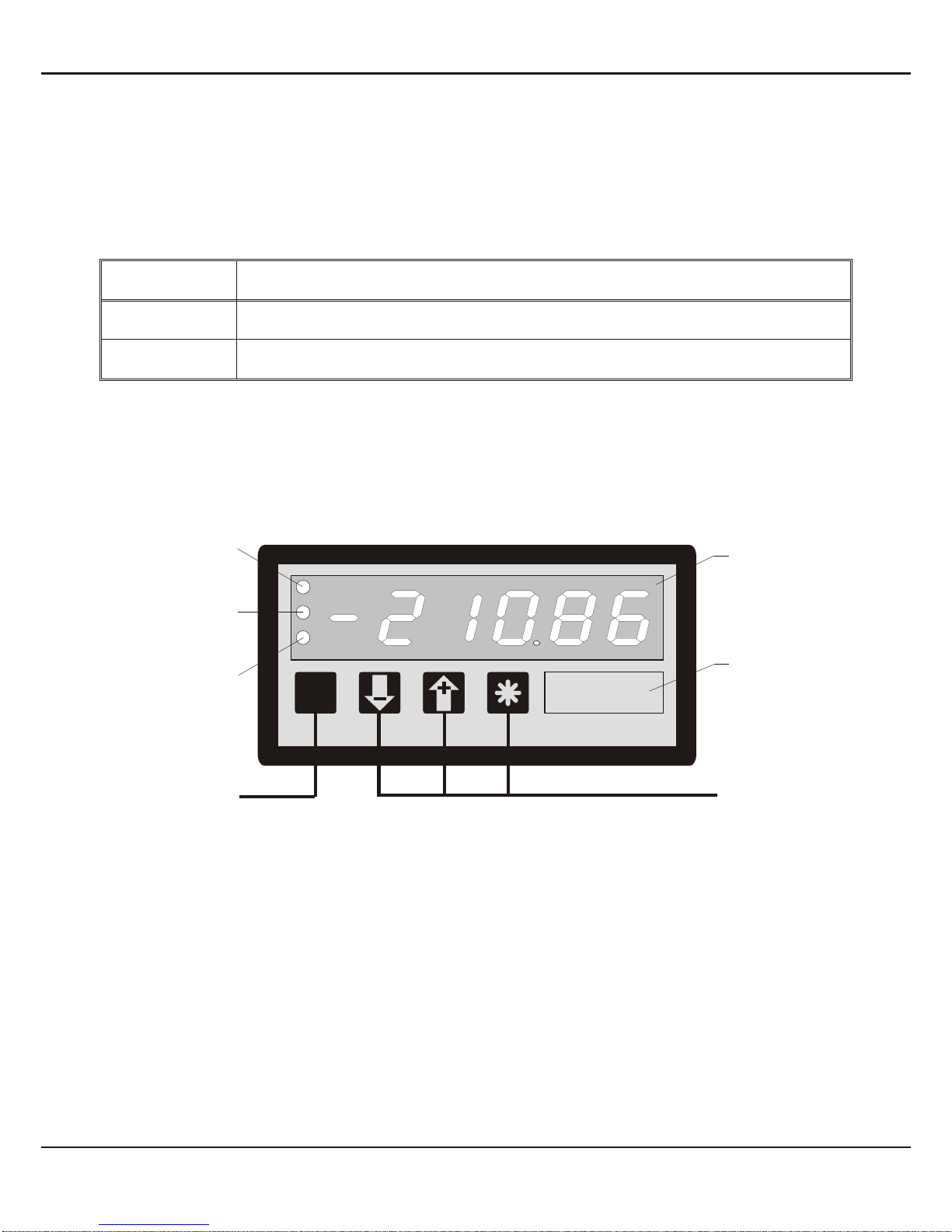
6-decades display
Insertion shield
for dimensions
LED2
LED1
LED3
Programming button function bottons
7. Modes
Theoperationandtheprogrammingofthepanelmeterisorganizedinseveralstates:
•Operation level
•Access-code level
•Programm level
7.1. Operation level
In the state “operation level” the normal functions of the instrument are activated. A
normal measurement cycle looks like below:
•Read the value of encoder, calculate and display
The function of the -key depends on the value of the parameter 0-08 .
Parameter 0-08
Function of pushbutton “*” by pressing
0No function
1displayed encoder value is set to zero
2clear zero setting
7.2. Access-code level
The state “access-code level” becomes active by pressing the pushbutton du-
ring the state “operation level”. The display shows “c000". During the state ”access-
code level" the normal functions of the instrument are active.
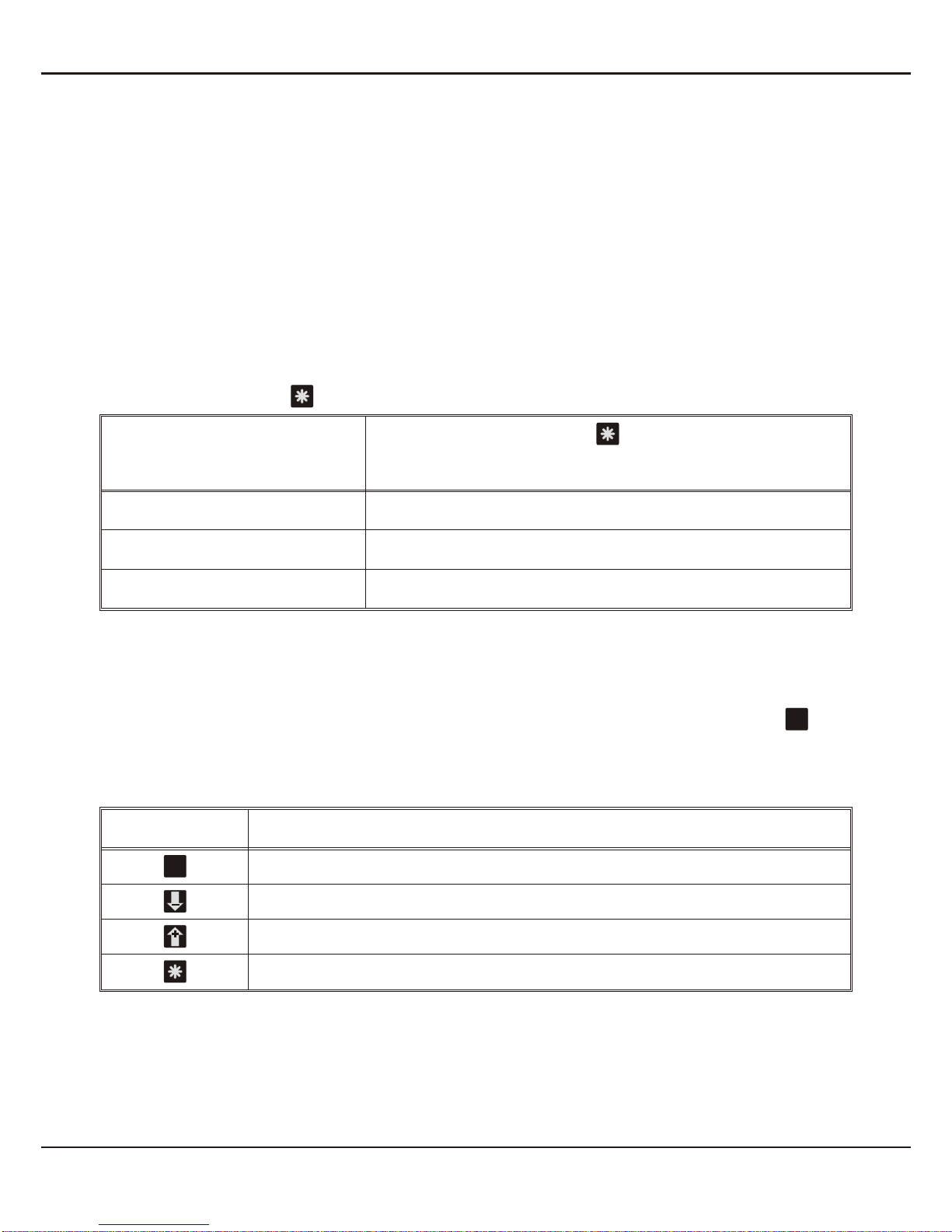
pushbutton Function
Confirm of the displayed access-code
Increase the access-code
Decrease the access-code
no function
10 ERMA-Electronic GmbH
7. Modes
PP
P
P

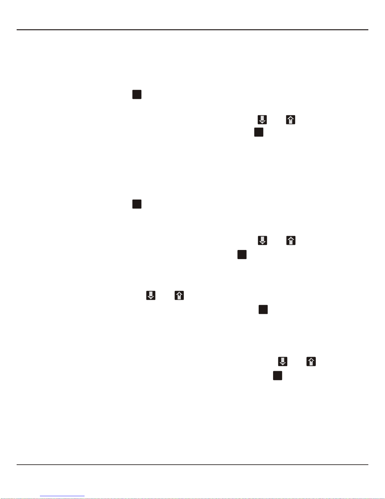
7.3. Programming level
The state “programm level” becomes active by entering the right access-code. The
access-code must be confirm by pressing the pushbutton . The programming is
organized in following steps:
•Selection of a programming level
•Selection of a parameter
•Change of the selected parameter
Pushbutton Press Pressing during 3 sec.
Selection of
- Programming level
- Parameter -
Decrease of
- Programming level
- Number of parameter
- Value of parameter
-
Increase of
- Programming level
- Number of parameter
- Value of parameter
-
-Break the programming routine
ERMA-Electronic GmbH 11
7. Modes
PP
P
P
8. Procedure of programming
The procedure of programming is organized in several different steps.
Access to the selection of the programming levels
•Pressing pushbutton => access-code enter is active
•The display shows “c000"
•Changing the access-code by pressing the pushbutton or and confirm
the changed access-code by pressing the pushbutton
If the entered access-code is not correct, the instrument will jump back to the state
“operation level”.
8.1. Changing or controlling parameters
Activating the programming routine
•Pressing pushbutton
•LED 3 flashs green
•The display shows “c000"
•Changing the access-code by pressing the pushbutton or
•Confirm access-code by pressing the pushbutton
•The display shows “P-00"
Leaving the programming routine
•Pressing the pushbutton or until the display shows “PEnd”
•Confirm the display “PEnd” by pressing the pushbutton
•LED 3 is off
•The active state of the panel meter is “operation level”
Selection of the programming level
•Selecting the programming level by pressing the pushbutton or
•Confirm the programming level by pressing the pushbutton
•Thedisplayshowsthenumberoftheparameteroftheselectedprogramminglevel
For example: “0-00" => parameter 0 of the programming level 0
12 ERMA-Electronic GmbH
8. Procedure of programming
PP
P
P
P
P
P
P
P
P
P
P

Leaving the programming level
•Pressing the pushbutton or until the display shows “xEnd”
For example: “0End” => leaving programming level 0
For example: “2End” => leaving programming level 2
•Confirm the display “xEnd” by pressing the pushbutton
•The display shows the programming level
For example: “P-00" => for programming level 0
Selection of the parameter
•Selection the parameter by pressing the pushbutton or
•Confirm the parameter by pressing the pushbutton
•The display shows the last programmed value of the selected parameter
Change and controll the selected parameter
•Change the value of the parameter by pressing the pushbutton or
•Confirm the value of the parameter by pressing the pushbutton
•The display shows the programming level and the number of the parameter
For example: “0-05" => parameter 5 of programming level 0
8.2. Overview of the programming levels
The parameters of the panel meter series are organized in different programming
levels. According to the design of the panel meter there are several programming
levels available.
P-00: Programming level for configuration of the panel meter
The configuration is used to adapt the absolute encoder and the panel meter.
ERMA-Electronic GmbH 13
8. Procedure of programming
PP
P
P
P
P

8.3. Programming level for configuration P-00
Param. Description Setting range Default
value
0-00 Resolution (Bits) 9 .. 25 12
0-01 Output code
0 -> Gray
1 -> Binary 0 .. 1 0
0-02 Master/Slave-Mode
0 -> Instrument = Master
1 -> Instrument = Slave 0 .. 1 0
0-03 Zero adjustment
0 -> Zero adjustment without sign
1 -> Zero adjustment with ± display 0 .. 1 0
0-04 Counting direction
0 -> increasing clockwise rotation
1 -> increasing anticlockwise rotation 0 .. 1 0
0-05 Scalingfactor 0.00001 .. 9.99999 1.00000
0-06 Offset value -99999 .. 999999 0
0-07
Programmable decimal points
0 -> XXXXXX
1 -> XXXXX.X
2 -> XXXX.XX
3 -> XXX.XXX
4 -> XX.XXXX
5 -> X.XXXXX
0 .. 5 0
0-08 Function of pushbutton “-”
0 -> No function
1 -> Display value of encoder
2 -> Display MAX value
0 .. 2 0
0-09 Access-code 0 .. 999 0
0End Leaving programming level 0
14 ERMA-Electronic GmbH
8. Procedure of programming

8.4. Scaling the display range
Thescalingofthedisplayrangeismatchedbyusingascaling-factorandanoffsetva-
lue. The calculation of the display value looks like below:
The overflow or underflow becomes active, if the displayed value is greater than
999999 or smaller than -99999.
•When overflow is activ the display shows “nnnnnn”
•When underflow is active the display shows “uuuuuu”
8.5. Programming quick reference
ERMA-Electronic GmbH 15
8. Procedure of programming
P-00 PEnd
Operation level
c000
0-00 P
PP
P
Code false
P
Code ok
PEncoder resolution
(bits)
Code
gray or binary
0-02
0-01
0-03
-
+-
+-
+
P
PMaster/Slave-Mode
Zero adjustment
0-04
0-05
-
+-
+P
PDirection of rotation
Scaling factor
0-06 POffset
Accesscode
0-07
-
+P
P
P
Decimal point
Function of "*"-button
-
+-
+-
+
-
+
+
P
1
-
-
2
3
3
aa
0-08
0-09
0End +
1
2
P3Discription
P
+
-
Push "P button"
Push "+ button"
Push "- button"
Display = (Enc_value - Zero_adjustmet) x Sca_faktor + Offset value
9. Software functions
9.1. Master/Slave-Mode
Master-ModeParameter 0-02 have to be programmed to 0
Forreadingthevalueoftheencodertheclockisgeneratedbytheinstrument.A fixed
clock frequency of 200 kHz is generated by the instrument.
Slave-Mode:Parameter 0-02 have to be programmed to 1
Theclocksignalhavetobegeneratedbyanotherinstrument.Thedatatransmission
between the encoder and the instrument dependent on this “external clock”.
In slave mode attention should be paid to:
•External clock may not exceed 100 kHz
•Pause of clock brushs have to be min. 500 µs
•The encoder value can be displayed with 80 values per second
9.2. Zero point adjustment
Sometimes an exactlymechanical zero point adjustment isn´t possible. But it´s pos-
sible to adjust the zero point by software.
9.2.1. Zero point adjustment by pressing button
The zero point can be changed by pressing the button. Parameter 0-08 have to
be programmed to 1.
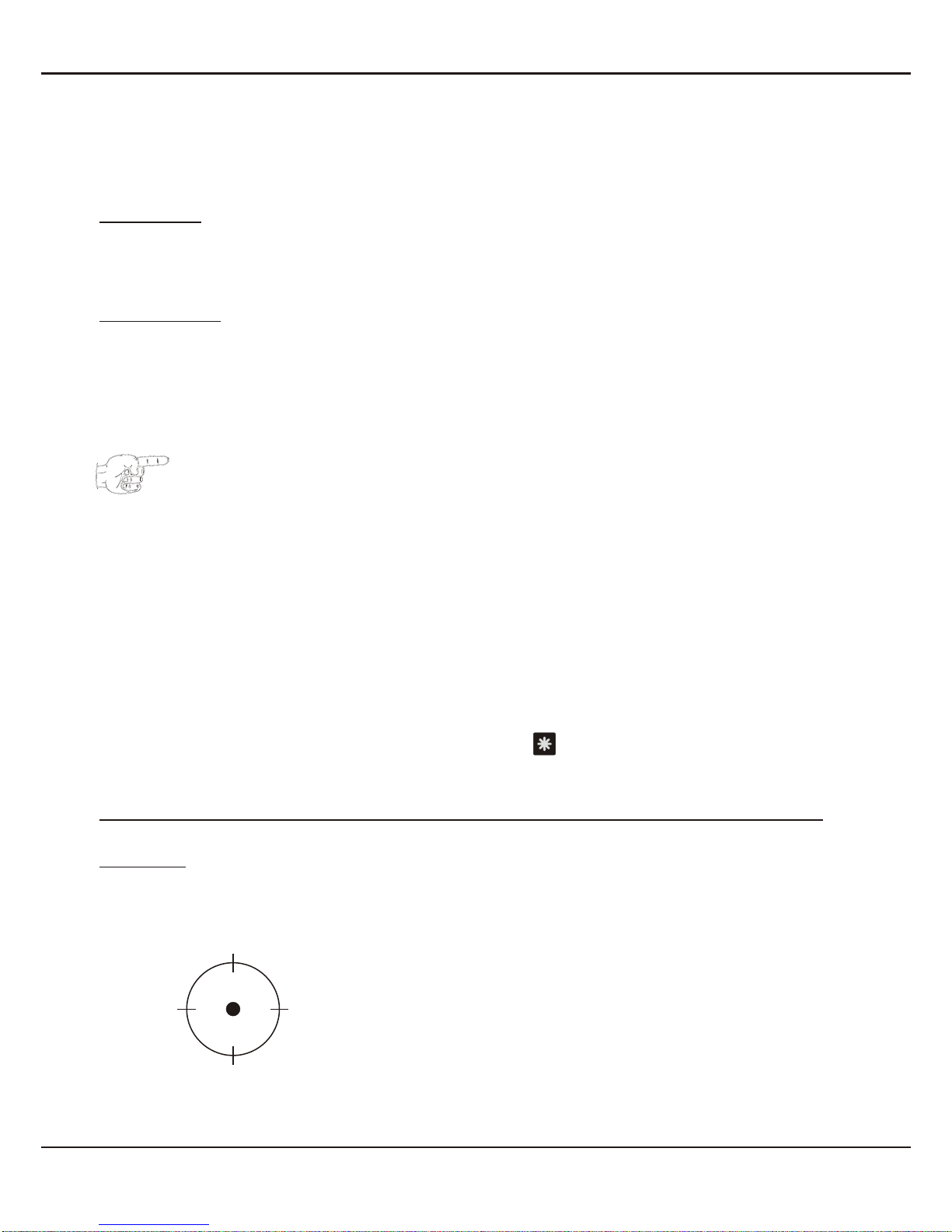
1. Zero point adjustment with sign: Parameter 0-03 have to be programmed to 1
Example:
Absolute Encoder SSI-Encoder, singeltur´n
Resolution: 4096 steps per rotation
Display range without changing of the zero point
16 ERMA-Electronic GmbH
9. Software functions
0
1024
2048
3072
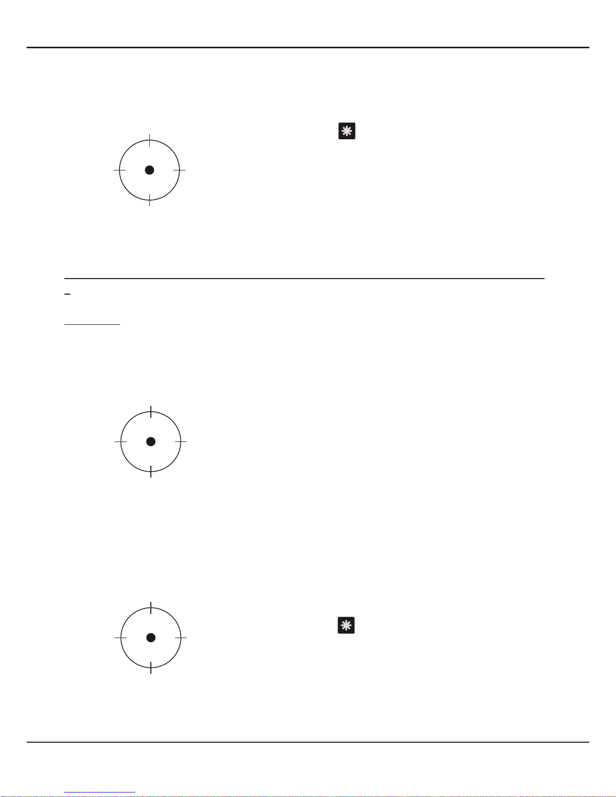
Display range with changing of the zero point
The pushbutton have been pressed by a display
of 2048
2. Zero point adjustment without sign: Parameter 0-03 have to be programmed to
0
Example:
Absolute Encoder SSI-Encoder, singleturn
Resolution: 4096 steps per rotation
Display range without changing of the zero point
Display range with changing of the zero point
The pushbutton have been pressed by a display
of 2048
ERMA-Electronic GmbH 17
9. Software functions
2048
-1024
0
1024
0
1024
2048
3072
2048
3072
0
1024

9.2.2. Zero point adjustment by offset value
The calculation of the programmed offset value (parameter 0-06) looks like below:
There can be a ± display, as a result of programming an offset value.
Attention should be paid to:
•Thechargingoftheoffsetvalueisfollowedafterthechargingofthesca-
ling-factor.
•The Parameter 0-03 have to be programmed to 1 for a +display
9.3. Directions of rotations
The direction of rotation can be changed by software function. The encoder will
usually count in increasing direction, if the driving shaft turns with clockwise rotation
(top view at the driving shaft).
Increasing values with clockwise rotation (top view at the driving shaft),
Parameter 0-04 have to be programmed to 0
Increasing values with anti-clockwise rotation (top view at the driving shaft),
Parameter 0-04 have to be programmed to 1
9.4. Main reset
The main reset is performed by pressing a key combination at the front of the panel
meter. By doing this all parameters are setting to the default value. The value of the
parameter 0-00 (input range) is not changing by the main reset.
During the main reset the display shows “Init.”.
Perform the main reset by
Pressing the pushbuttons , and at the same time until “Inlt” is dis-
played.
18 ERMA-Electronic GmbH
9. Software functions
Display = (Enc_yalue - Zero_adjustmet) x Sca_faktor + Offset value
PP

10. Error codes
10.1. Encoder not connected “Err01"
•The display flashs and indicate “Err01"
•Signalizes that no encoder have been connected to the instrument
10.2. Waiting for data input “Err02"
•The display flashs and indicate “Err02"
•Signalizes in slave-mode, that after the connection of an encoder no data input
have been received by the instrument.
10.3. External clock frequency too high “Err03"
•The display flashs and indicate “Err03"
•Signalizes in slave mode, that the clock frequency of the “external clock” is too
high (> 100 kHz).
ERMA-Electronic GmbH 19
10. Error codes

11. Technical Specifications
11.1. Electrical datas
SSI signal input : singleturn or multiturn
Resolution : 9 .. 25 bit
Code : binary or gray
Clock output : driver RS 422/485
Clock input : receiver RS 422/485
Data input : receiver RS 422/485
Master mode
Clock frequency : internal 200 kHz
Conversion rate : approximate 80 values/second
Slave mode
Clock frequency : external, max. 100 kHz
Break of clock brushs : min. 500 µs
Conversion rate : approximate 80 values/second
Power supply DC : 18 .. 36 V DC (isolated)
power consumption : max. 50 mA
optional : 12 V DC, ± 10 % (isolated)
power consumption : max. 100 mA
optional : 5 V DC, ± 10 % (isolated)
power consumption : max. 200 mA
Isolation voltage : 500 V /1 min
11.2. Mechanical datas
Display : 6 decades, 14 mm, red
: decimal point programmable
: preliminary zero suppression
: - sign at negative values
Operation, keyboard design : front membrane with push buttons
Case : panel mounting DIN 43 700
Dimensions (B x H x T) : 96 x 48 x 63,5 mm
Depth : 72 mm incl. screw terminal
Mounting : switch board mounting or
: mosaic-system mounting
Weight : approx. 160 g
Connection : plug-in screw terminal
20 ERMA-Electronic GmbH
11. Technical Specifications
Table of contents
Other Erma Electronic Measuring Instrument manuals


Popular Measuring Instrument manuals by other brands


Tektronix
Tektronix SDA601 Service manual

Thermo Scientific
Thermo Scientific AQUAfast AQ3700 user guide

Gossen MetraWatt
Gossen MetraWatt MAVOWATT 210 ROGOWSKI operating instructions

BRONKHORST
BRONKHORST FLOW-BUS instruction manual

YOKOGAWA
YOKOGAWA MT210 user manual

PHYWE
PHYWE Timer 2-1 operating instructions


