5. Function
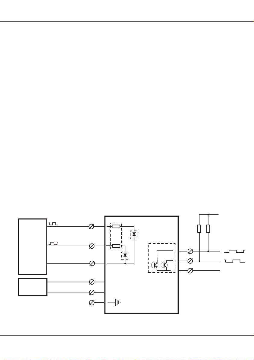
The converter FT 9004 is a frequency divider in a snap-in housing for 35mm rail
mounting. The unit is designed for dividing pulse chains of incremental encoders by a
predetermined value. The desired divider value is adjustable by the user. The unit
can be used for input frequencies up to 90 kHz. Up-down counting is possible without
loss of pulses.
There are two operating modes available. One mode is able to divide two input pulse
chains 90° out of phase applied to the input channels "Input A" and "Input B". A se-
cond operating mode uses only input channel "Input A" for the input pulse chain. The
other input channel "Input B" decides when using this mode the direction of the output
pulse chains.
There are two open collector output channels "Out 1" and "Out 2". At both operating
modes the output channels "Out 1" and "Out 2" are generating ouput pulse chains 90°
out of phase, divided by the adjusted divider value.
The input channels are isolated. Source signals of at least 5 mA are needed to drive
the input channels. The input voltage level can be set by the user by internal jumpers
to input levels of 5 V, 12V and 24 V.
The output channels are isolated from the input channels and the power supply input.
The output channels are provided as open collector outputs. So the user can crea-
te by resistances output voltages from 3 V to 30 V according to his requirements.
6. Jumper- and DIP-Switch Configurations
For adjustments there are three jumperblocks and two 8-pole DIP switches inside of
the case. To access the jumperblocks and the DIP switches the case has to be ope-
ned. This is simple done with the aid of a small screwdriver. There are two little flat on
each side of the case which must be pressed inwards. The top of the case can now be
separated from the base and the PCB can be pulled out (pic.2).
7ERMA-Electronic GmbH
5. Function
Picture 2