ERNITEC LON Box I151SX User manual

LON®
Box X
I151SX-ALARM
I151SX-REMOTE
Installation
Manual
2853-00009
SYS EM

S
Y
S
EM

Validity
This manual covers the following LON
®
Boxes:
yLON
®
Box type I151SX-ALARM
yLON
®
Box type I151SX-REMOTE
Compatibility
This manual describes all possible features of the I151SX LON
®
Box. However, actual features
supported, depends on the connected equipment.
Approvals
All LON
®
Box types are CE certified and approved with respect to EN 50081-1, EN 50130-4
(EMC) and EN 60950 (LVD).
Operation
I151SX-ALARM RS232-to-LON Alarm Interface.
The I151SX-ALARM interface box is used as an interface for alarm equipment, sending serial
alarms to SYSTEM X. Ernitec alarm protocols IEC, Serial Alarm, and extended Serial Alarm are
supported.
I151SX-REMOTE SYSTEM X-to-SYSTEM 500M/1000M Interface
The I151SX-REMOTE interface box, is used as an interface, between SYSTEM X and SYSTEM
500M/1000M. It enables SYSTEM X to control SYSTEM 500M/1000M, configured as remote
systems.
Setup
There are no setup functions in the LON
®
Box itself. All functions and settings are
programmed using the NodeManager S111SX software.
LON®
Network
For details on the LON
®
Network, installation, cabling and termination, please see the
NodeManager S111SX Installation Manual.
Trademarks
Echelon, LON and
L
ON
W
ORKS are trademarks of Echelon Corporation registered in the
United States and other countries.
Printing Date: 10-02-2003
2853-00009 Page 1
S
Y
S
EM

Installation
Unpacking the LON®
Box
After unpacking the LON
®
Box, carefully check for any signs of damage. Any such damage
should be reported to your supplier, before installation.
Check that the packing carton contains the following items:
y1 pcs. SYSTEM X LON
®
Box.
y1 pcs. LON
®
Box X Installation Manual (this manual)
y1 pcs. screw kit.
Box Installation
Choose a plane surface to prevent the box from being twisted and thereby becoming leaky.
When installed outdoor the box should be oriented with the cable glands pointing
downwards.
Drilling pattern is shown on the back of the box.
Box dimensions (excl. glands) are: 242 x 160 x 90mm (W x H x D).
Mains installation
The LON
®
Box can be supplied with either 115 VAC or 230 VAC mains voltage. The mains
voltage is selected by the mains voltage selection switch.
T1
MAINS IN
N L
SELECT
MAINS
J9
Ih=63mA
F1
S5
115
230
Mains selection switch
Mains input
L:
N:
:
Live
Neutral
Earth
The LON
®
Box must be used with a 3-wire mains connection (2W+PE @ min. 0,75mm
2
).
Terminals marked with hazardous live symbol requires installation by an instructed person.
If permanently connected to mains, a readily accessible disconnect device shall be
incorporated in the building installation wiring.
If pluggable connection to mains, the socket-outlet shall be installed near the equipment and
shall be easily accessible.
Note: The unit is equipped with two PTC-fuses with automatic reset function. In case of malfunc-
tion always return the unit for repair. The references below are intended for information only.
F1: (BC Components, type 2322 660 66393)
I
hold
= 63mA, I
trip
= 95mA, Initial resistance = 120R
F2: (BOURNS, type MF-R075)
I
hold
= 750mA, I
trip
= 1.5A, Initial resistance = 0R18
S
Y
S
EM
Page 2 2853-00009
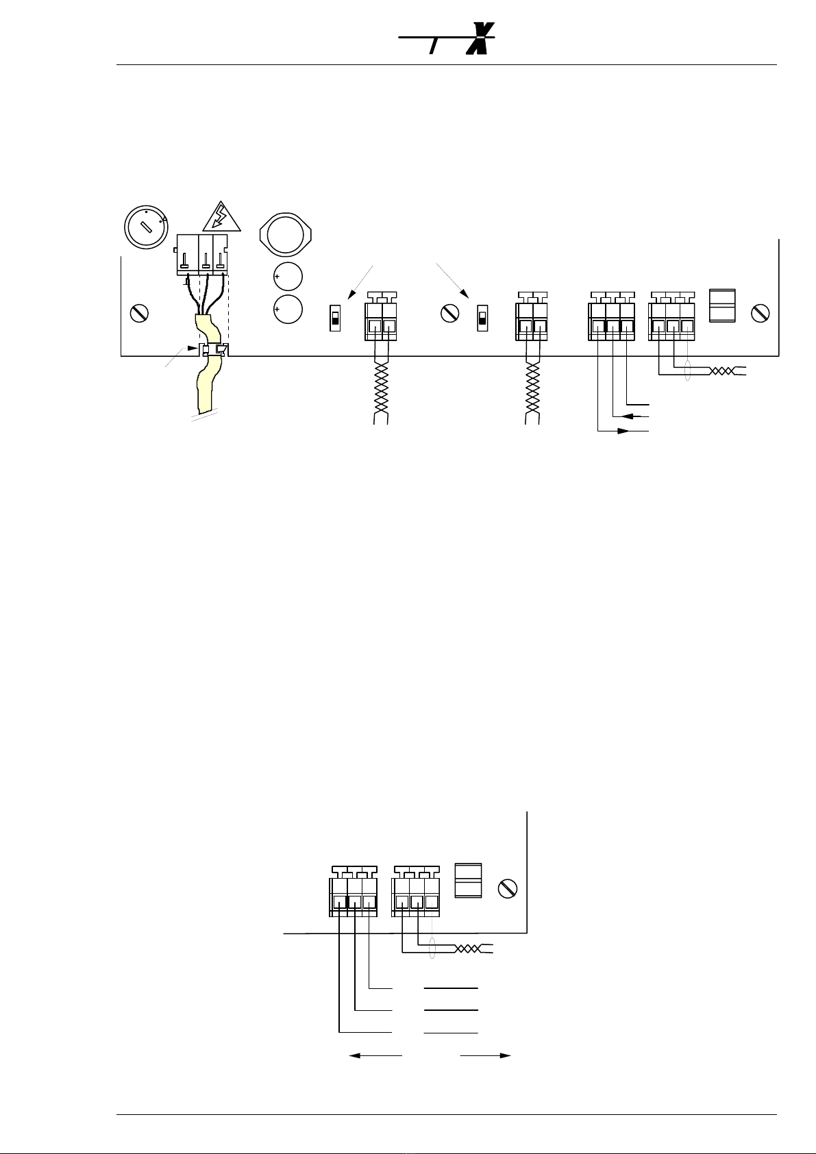
Cable connections
It is of utmost importance that all cable connections are carried out exactly as described, in
order to avoid malfunction or damage to the LON
®
Box and/or the connected equipment.
All cables to and from the LON
®
Box are fed through the cable glands. Choose an appropriate
size gland for the actual cable and tighten the glands when all cables are connected.
MAINS IN
N L
SELECT
MAINS
J9
J7
TERM
OFF
S3
B-B+
RS485 TX
ON
TERM
S2
OFF
ON
S5
115
230
RS485 RX/TX
B+ B-
Cable tie
Mains cable
230VAC±10%, 33mA
115VAC±10%, 66mA
45-60Hz
GND
TX RX GND
RS232
LINE LINE
LON
J5 J8
LON
Shield
GND
Rx
Tx
RS232
+ -
RS485 Rx/Tx
+ -
RS485 Rx/Tx
RS485 termination
J6
In order to fulfil safety standard EN 60950, all cables carrying mains voltage, must be secured
to the PCB by means of e.g. a cable tie, as shown in the above drawing.
LON®
For details on the LON
®
Network, installation, cabling and termination, please see the
NodeManager S111SX Installation Manual.
To comply with EMC/EMI standard EN 50130-4, shielded LON
®
cable must be used.
Connection is polarity insensitive.
RS232 (I151SX-ALARM)
Connects to a PC COM port, or similar.
vData format: 8N1
vBaud rate: 110 ~ 38400 bps
GND
TX RX GND
RS232
LINE LINE
LON
J5 J8
LON
Shield
GND
Rx
Tx
Pin 5
Pin 3
Pin 2
PC COM
Max. 15 meters
2853-00009 Page 3
S
Y
S
EM

RS232 (I151SX-REMOTE)
Connects to an RS232 port on SYSTEM 500M/1000M.
Serial port (SIO 1 or 2) setup, on SYSTEM 500M/1000M:
vType: RS232
vDevice: IEC
vBaud rate: 19200
For furter details, please see the Programming Manual for SYSTEM 500M/1000M.
GND
TX RX GND
RS232
LINE LINE
LON
J5 J8
LON
Shield
GND
Rx
Tx
Pin 5
Pin 3
Pin 2
500M/1000M
SIO 1 or 2
Max. 15 meters
RS485
The RS485 connections are not used in I151SX-ALARM and I151SX-REMOTE.
Protocols (I151SX-ALARM)
The I151SX-ALARM supports 3 different protocols: SAP, xSAP and IEC.
Serial Alarm Protocol (SAP)
The SAP protocol is a simple alarm protocol, using Xon/Xoff flow control.
Data Format
vBaud Rate: 1200 ~ 38400
vData Bits: 8
vParity: None
vStop Bits: 1
vFlow control: Xon/Xoff
Frame format
1 byte1 byte1 byte1 byte1 byte1 byte
"000" - "512"41 or 43 Hex53 Hex
XOR sumASCII format"A" or "C""S"
ChecksumAlarm numberAlarm CommandHeader
Header
Always ASCII "S" (53 Hex).
S
Y
S
EM
Page 4 2853-00009

Alarm Command
One ASCII character.
Alarm ON is "A" (41 Hex). Alarm OFF is "C" (43 Hex).
Alarm Number
A 3-digit alarm number in ASCII format ("001" ~ "512").
Checksum
The XOR result of the previous 5 bytes.
Xon/Xoff Flowcontrol
The SAP protocol uses Xon/Xoff flowcontrol. The Xon character is DC1 (11 hex), and Xoff is
DC3 (13 hex).
The Xon/Xoff principle is as follows:
When the receiver buffer is 80% full, the receiver transmits an Xoff character to stop the
transmitter. When the buffer is only 20% full the receiver transmits an Xon to start the
transmitter again.
To be able to send both DC1 and DC3 as data, the protocol uses "the character stuffing
principle". Character stuffing means that the transmitter is transmitting an extra DC1
character if it wants to transmit DC1 as data. Then the receiver knows that two DC1
characters means "DC1-data" and one DC1 means "Xon".
Example
In order to set alarm number 45 ON, the following string must be transmitted:
53 41 30 34 35 23
53: "S" - Header
41: "A" - Alarm ON
30,34,35: "045" Alarm number
23: XOR checksum (53 xor 41 xor 30 xor 34 xor 35)
Extended Serial Alarm Protocol (xSAP)
The xSAP protocol is similar to the SAP protocol, but without the limitation of max. 512
alarms.
Data Format
vBaud Rate: 1200 ~ 38400
vData Bits/Parity/Stop bits: 8/N/1
vFlow control: Xon/Xoff
Frame format
1 byte'n' byte(s)1 byte1 byte1 byte
"N
1
" - "N
n
"41 or 43 Hex53 Hex
XOR sumASCII format"A" or "C"ASCII format"S"
ChecksumAlarm numberAlarm CommandNumber of bytesHeader
Header
Always ASCII "S" (53 Hex).
Number of Bytes
Total number of bytes including checksum, but excluding Header.
2853-00009 Page 5
S
Y
S
EM

Alarm Command
One ASCII character.
Alarm ON is "A" (41 Hex). Alarm OFF is "C" (43 Hex).
Alarm Number
Alarm number in ASCII format ("Number
1
" ~ "Number
n
").
Checksum
The XOR result of all previous bytes, including Header
Xon/Xoff Flowcontrol
The SAP protocol uses Xon/Xoff flowcontrol. The Xon character is DC1 (11 hex), and Xoff is
DC3 (13 hex).
The Xon/Xoff principle is as follows:
When the receiver buffer is 80% full, the receiver transmits an Xoff character to stop the
transmitter. When the buffer is only 20% full the receiver transmits an Xon to start the
transmitter again.
To be able to send both DC1 and DC3 as data, the protocol uses "the character stuffing
principle". Character stuffing means that the transmitter is transmitting an extra DC1
character if it wants to transmit DC1 as data. Then the receiver knows that two DC1
characters means "DC1-data" and one DC1 means "Xon".
Example
In order to set alarm number 45 ON, the following string must be transmitted:
53 05 41 34 35 16
53: "S" - Header
05: Number of bytes
41: "A" - Alarm ON
34,35: "45" Alarm number
16: XOR checksum (53 xor 05 xor 41 xor 34 xor 35)
IEC Alarm Protocol
Information about the IEC protocol can be found in the Ernitec Protocol Manual, available on
request.
S
Y
S
EM
Page 6 2853-00009
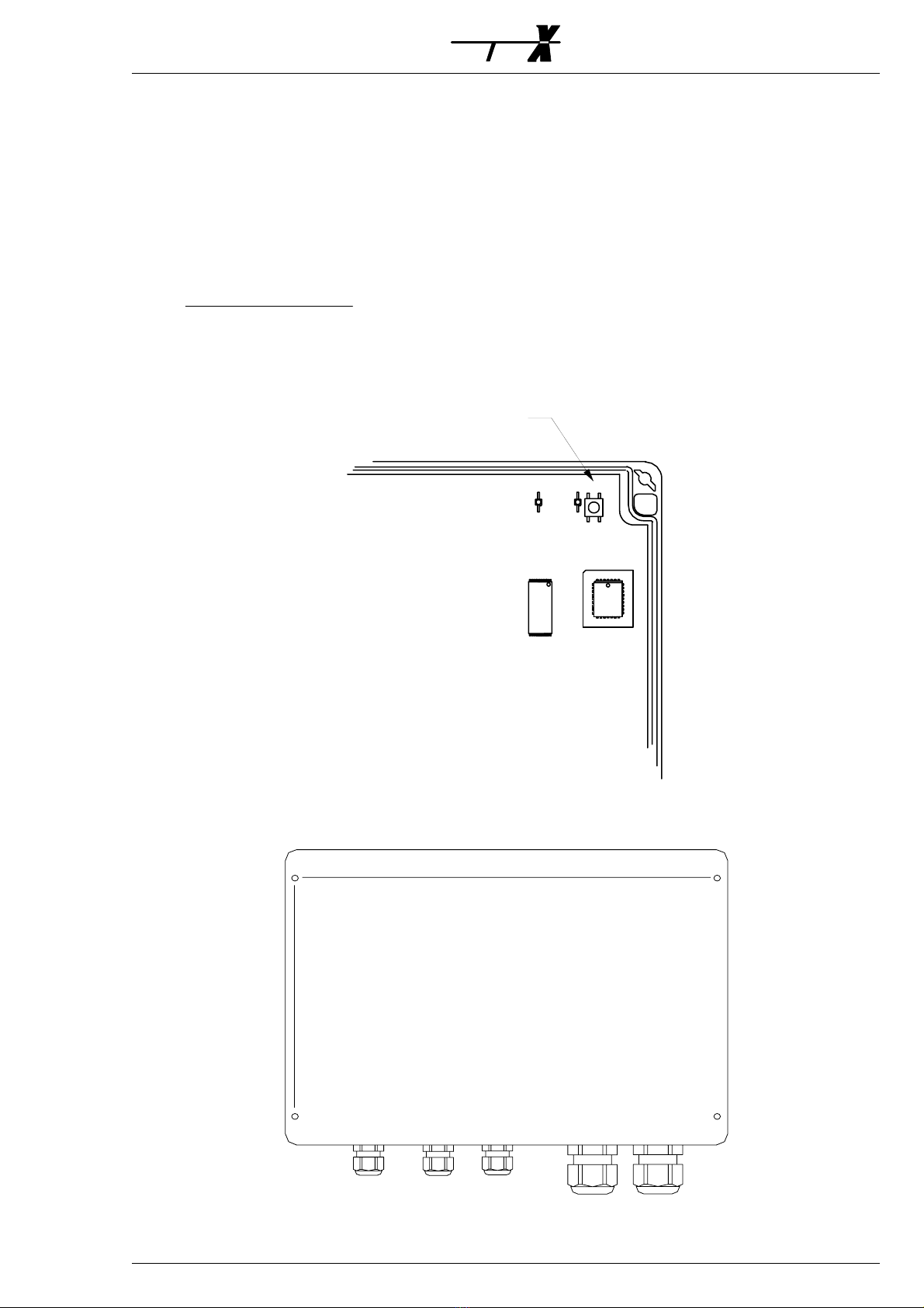
Service pin
When the LON
®
Box is connected to the LON
®
Network, the service pin must be pressed for
the NodeManger software to identify the LON
®
Box. Use a small screwdriver, or similar, to
press the service pin. The yellow LED next to the service pin will light up shortly, when the
service pin is pressed.
Make sure that the NodeManager software is running, and online, prior to pressing the
service pin.
It is of out most importance to keep track of the order in which service pins are pressed on
the various SYSTEM X units.
Please see the NodeManager Manual for full details on the function, and importance, of the
service pin.
Service pin
RUN LED
LON SERVICE
Drilling Pattern
228mm
130mm
Drilling pattern
2853-00009 Page 7
S
Y
S
EM

Ernitec Offices
Ernitec A/S
(Headquarters)
Hørkær 24
DK-2730 Herlev
Denmark
Phone: +45 44 50 33 00
Fax: +45 44 50 33 33
www.ernitec.com
Ernitec GmbH
(German Branch Office)
Stormarnring 28
D-22145 Stapelfeld
Germany
Phone: (040) 67 56 25 0
Fax: (040) 67 56 25 25
www.ernitec.com
Ernitec UK
(UK Branch Office)
Gerrard House
Worthing Road
East Preston
West Sussex BN16 1AW
England
Phone: 01903 77 27 27
Fax: 01903 77 27 07
www.ernitec.com
Ernitec France
(French Branch Office)
N
o
29 Parc Club du Millénaire
1025 rue Henry Becquerel
F-34036 Montpellier cedex 1
France
Phone: 04 67 15 10 15
Fax: 04 67 64 01 81
www.ernitec.com
Ernitec ME
(Middle East Office)
Hamra - Makdesi Street
Younis Center - 5th floor
Office no. 503
P.O.Box 113/5721
Beirut
Lebanon
Phone: +961 1 751 796
Fax: +961 1 751 795
www.ernitecme.com
S
Y
S
EM
Page 8 2853-00009
Table of contents
Popular Recording Equipment manuals by other brands


Solid State Logic
Solid State Logic Network I/O SB 8.8 Installation notes

Rotel
Rotel RSP-975 owner's manual

Mitsubishi
Mitsubishi DX-TL1600EM Installation and operation manual

Sonosax
Sonosax SX-R4 user manual

GE
GE Masoneilan SVI II ESD Installation and maintenance manual

Freedom
Freedom Bodyworn troubleshooting guide


