ero electronic MEMOCAL 2000 User manual

170.MAN.MEM.2D1 01/0
rUSER MANUAL MEMOCAL
2000
M20-e-0.p65 7/9/01, 2:39 PM1

CONTENTS
SECTION 1 GENERAL INFORMATION
1.1 INTRODUCTION ........................................................... Page 4
1.2 PRODUCT SPECIFICATIONS ................................................ 4
1.3 SERIAL INTERFACE ............................................................. 11
1.4 SEQUENTIAL FUNCTION ROUTINE ................................... 11
1.5 SPECIAL FUNCTIONS .......................................................... 11
1.6 CODING ................................................................................. 12
1.7 IDENTIFICATION LABEL ...................................................... 12
SECTION 2 INSTRUMENT CONFIGURATION
2.1 FRONT PANEL DESCRIPTION ............................................ 13
2.2 KEYBOARD DESCRIPTION ................................................. 14
2.3 INSTRUMENT CONFIGURATION ........................................ 16
SECTION 3 OPERATING INSTRUCTIONS
3.1 PRELIMINARY ....................................................................... 19
3.2 TC MEASUREMENT ............................................................. 21
3.3 RTD MEASUREMENT ........................................................... 23
3.4 mA MEASUREMENT ............................................................. 24
3.5 TX MEASUREMENT ............................................................. 29
3.6 mV MEASUREMENT ............................................................. 33
3.7 OHM MEASUREMENT .......................................................... 37
3.8 TC SIMULATION ................................................................... 38
3.9 RTD SIMULATION ................................................................. 41
3.9 mA GENERATION ................................................................. 42
3.10 TX SIMULATION .................................................................... 46
3.11 mV GENERATION ................................................................. 51
3.12 OHM SIMULATION ................................................................ 56
SECTION 4 SEQUENTIAL FUNCTION ROUTINE
4.1 HOW TO CONSTRUCT AND STORE A NEW
SEQUENTIAL FUNCTION ROUTINE ................................... 58
4.2 HOW TO MODIFY A ROUTINE ............................................. 60
4.3 HOW TO RUN A ROUTINE ................................................... 61
SECTION 5 ERROR MESSAGES
5.1 LOAD ERRORS ..................................................................... 63
5.2 ERROR MESSAGES ............................................................. 64
SECTION 6 MANTENANCE
6.1 POWER SUPPLY .................................................................. 65
6.2 BATTERY RECHARGE ......................................................... 66
6.3 BATTERY MAINTENANCE ................................................... 67
6.4 BATTERY REPLACEMENT .................................................. 67
6.5 HOW TO CLEAN THE INSTRUMENT .................................. 67
6.6 INTERNAL FUSES ................................................................ 67
6.7 INSTRUMENT MAINTENANCE ............................................ 67
M20-e-0.p65 7/9/01, 2:39 PM2

CAUTIONS:
1) The AC adapter is intended for indoor use only.
2) To avoid electric shock, do not use the AC adapter close to steam generator or water basin.
3) Before connecting the AC adapter to the power line, verify the integrity of the adapter case. If the case is dam-
aged, replace it.
M20-e-0.p65 7/9/01, 2:39 PM3

4
·Square root extraction and quadratic signal generation.
·Programmable scaling for mA, mV and V measurement and
generation.
·Built in 24 V DC power supply for 2-wires transmitter excitation
and measurement.
·Programmable external cold junction compensation value.
·Peak and valley data hold.
·Direct connection for all input types (no special connectors are
required for TC inputs).
·Up to 50 steps program or smaller programs to total of 50 steps.
·Ramp, soak and step function capability
·2 dry contact logic inputs for program advance/wait.
1.2 PRODUCT SPECIFICATIONS
1.2.1 GENERAL SPECIFICATIONS
Case: ABS grey case, color similar to RAL 6038.
Case protection: IP 20.
Terminal: 3 external screw FEMALE plugs f4 mm.
Input protection: all measured and generated ranges are protected
against fault connection to signals up to 30 V AC/DC.
Display: 2 rows by 16 characters alphanumeric back lighted LCD
display
Weight: 600 g. max. (1.4 lb.).
Power supply: 4 batteries AA size :
- Alkaline 1,5 V or
- Ni-Cd 1,2 V or
- Ni-H 1.2 V.
SECTION 1 GENERAL INFORMATION
1.1 INTRODUCTION
The MEMOCAL 2000 is a versatile, portable, hand-held calibrator
developed to solve two different and coexisting customer needs:
field calibration (maintenance) and laboratory calibration (mainte-
nance, quality test, process simulation, training, etc..).
- The field calibration requires small dimensions, no additional
accessories, long battery life, ergonomy, friendly interface, low
temperature drift, high noise immunity and simple programming
capabilities.
- The laboratory requires: interface for data loggers or supervision
and control systems, large range of I/O capabilities, high
accuracy and stability over time.
The features listed below give an idea of the possible applications
and use facility offered by this instrument
·Accuracy 0.015 % (*)
·Temperature drift 0.1 mV/°C
·Operates with standard 1.5 V AA type alkaline batteries or
rechargeable batteries (Ni-Cd or Ni-MH)
·Advanced battery power management for circuit stand-by mode
when not in use.
·24 hours (average) battery life operation.
·Built in bi-directional RS-232 interface for remote programming
and data recording
·Autoranging during measurement and generation.
·Simulates and measures T/C signals (15 T/C type) and RTD
signals (Pt 100 and Ni 100).
·Generates and measures mA, mV, V and OHM signals.
M20-e-1.p65 7/9/01, 2:39 PM4

5
Battery life: 24 hours (average) with Ni-MH batteries.
Recharging time: 12 hours
AC/DC adapter: input: from 100 to 250 V AC, 47 to 73 Hz, 100 mA.
output: 7.5 V, 1.2 A DC.
Insulation resistance: > 100 MWaccording to IEC 348.
Isolation voltage: 1500 V r.m.s. according to IEC 348.
Electromagnetic compatibility and safety requirements:
This instrument is marked CE.
Therefore, it is conforming to council directives 89/336/EEC
(reference harmonized standard EN 50081-2 and EN 50082-2) and
to council directives 73/23/EEC and 93/68/EEC (reference harmo-
nized standard EN 61010-1).
Installation category: II
D/A conversion: dual slope integration.
Resolution: + 20000 counts
Common mode rejection ratio: 120 dB @ 50/60 Hz.
Normal mode rejection ratio: 60 dB @ 50/60 Hz.
Sampling time: 500 ms.
Display update time: 500 ms.
Temperature drift: 0.0028 %/°C or 28 ppm/°C (CJ excluded).
Operating temperature: from 0 to +40 °C.
Storage temperature: from -10 to +60 °C.
Humidity : from 20% to 85 % RH non condensing.
Protections: WATCH DOG circuit for automatic restart.
1.2.2 INPUTS
A) THERMOCOUPLE MEASUREMENT
Type : B, E, J, K, L, N, Ni/Ni-18%Mo, PLII, R, S,T, U, W, W3 and
W5 keyboard programmable.
Engineering unit: °C or °F keyboard programmable.
Burn out : Detection of the open input circuit (wires or sensor) with
"OPEN" indication.
Cold junction: automatic compensation from 0 to 45 °C.
Cold junction compensation error: + 0.3 °C + 0.005 °C/°C
(+ 0.5°F + 0.005 °F/°F).
External cold junction compensation: programmable
- from -20 °C to +80 °C or -4.0 °F to 176.0 °F for TC type J, K, T,
E, R, S, U, L, PLII;
- from 0 °C to 80 °C or from 32 °F to 176 °F for TC type B, N, Ni/
Ni18%Mo, W, W3 and W5 ).
Input impedance:> 10 MW.
External resistance: 100 Wmax, maximum error 0,1% of span.
Calibration: according to IPTS-68 or ITS 90 programmable
Standard range table when the engineering unit is equal to °C
TC type
J
K
T
Max. Error (CJ excl.)
0.2 °C
0.3 °C
0.5 °C
0.3 °C
0.1 °C
RESOL.
0,1 °C
0,1 °C
< 0,2 °C
0,1 °C
0,1 °C
RANGE
-200°C to 1200 °C
-200°C to 967 °C
968°C to 1370 °C
-200°C to 0 °C
1°C to 400 °C
M20-e-1.p65 7/9/01, 2:39 PM5

6
TC type
E
R
S
B
U (*)
L (*)
N
Ni/Ni
18%Mo
PLII
TC type
W (G)
W3 (D)
W5
RANGE
-200°C to 1000 °C
-50°C to 0 °C
1°C to 350 °C
351°C to 1684 °C
1685°C to 1760 °C
-50°C to 0 °C
1°C to 600 °C
601°C to 1760 °C
50°C to 100 °C
101°C to 200 °C
201°C to 600 °C
601°C to 1150 °C
1151°C to 1820 °C
-200°C to 600 °C
-200°C to 900 °C
0°C to 1410 °C
0°C to 1300 °C
-100°C to 961 °C
962°C to 1400 °C
RESOL.
0,1 °C
< 0,3 °C
< 0,2 °C
0,1 °C
< 0,2 °C
< 0,3 °C
< 0,2 °C
0,1 °C
< 3 °C
< 1 °C
< 0,5 °C
0,2 °C
0,1 °C
0,1 °C
0,1 °C
< 0,2 °C
0,1 °C
0,1 °C
< 0,2 °C
RESOL.
< 1 °C
< 0,3 °C
< 0,2 °C
0,1 °C
< 0,2 °C
0,1 °C
0,1 °C
< 0,3 °C
0,1 °C
0,2 °C
< 0,3 °C
RANGE
0°C to 50 °C
51°C to 100 °C
101 °C to 250 °C
251°C to 1530 °C
1531°C to 2300 °C
0°C to 100 °C
101°C to 1090 °C
1091°C to 2310 °C
0°C to 1096 °C
1097°C to 2250 °C
2251°C to 2315 °C
Standard range table when the engineering unit is equal to °F
TC type
J
K
T
Max. Error (CJ excl.)
0.5 °F
0.5 °F
2.0 °F
0.6 °F
0.9 °F
0.5 °F
0.2 °F
RANGE
-328 °F to 1382 °F
-328 °F to 32 °F
33 °F to 1772 °F
1773 °F to 2264 °F
2265 °F to 2498 °F
-328 °F to 32 °F
33 °F to 752 °F
RESOL.
0,1 °F
< 0,2 °F
0,1 °F
0,1 °F
< 0,3 °F
< 0,2 °F
0,1 °F
(*) Available only when IPTS-68 standard is selected
Max. Error (CJ excl.)
0.2 °C
1.4 °C
0.9 °C
0.4 °C
0.7 °C
1.1 °C
0.9 °C
0.4 °C
12.4 °C
4.1 °C
1.9 °C
0.7 °C
0.4 °C
0.2 °C
0.3 °C
0.5 °C
0.3 °C
0.2 °C
0.6 °C
Max. Error (CJ excl.)
2.9 °C
1.1 °C
0.8 °C
0.4 °C
1.4 °C
0.4 °C
0.3 °C
1.0 °C
0.3 °C
0.9 °C
1.0 °C
M20-e-1.p65 7/9/01, 2:39 PM6

7
TC type
N
Ni/Ni
18%Mo
PLII
W (G)
W3 (D)
W5
RANGE
-328 °F to 1832 °F
-58 °F to 32 °F
33 °F to 350 °F
351 °F to 500 °F
501 °F to 3062 °F
3063 °F to 3214 °F
-58 °F to 32 °F
33 °F to 140 °F
141 °F to 470 °F
471 °F to 3214 °F
122 °F to 212 °F
213 °F to 320 °F
321 °F to 600 °F
601 °F to 1250 °F
1251 °F to 1770 °F
1771 °F to 3276 °F
-328 °F to 1112 °F
-328 °F to 1299 °F
1300 °F to 1652 °F
RESOL.
0,1 °F
< 0,5 °F
< 0,4 °F
< 0,3 °F
< 0,2 °F
< 0,3 °F
< 0,5 °F
< 0,4 °F
< 0,3 °F
< 0,2 °F
< 4 °F
< 2 °F
<1 °F
< 0,5 °F
< 0,3 °F
<0,2 °F
0,1 °F
0,1 °F
< 0,2 °F
Max. Error (CJ excl.)
0.4 °F
2.6 °F
1.6 °F
1.2 °F
0.8 °F
1.2 °F
2.0 °F
1.6 °F
1.2 °F
0.8 °F
14.9 °F
5.0 °F
2.4 °F
1.2 °F
0.8 °F
0.5 °F
0.4 °F
0.3 °F
0.5 °F
Max. Error (CJ excl.)
0.4 °F
0.7 °F
0.8 °F
0.5 °F
0.5 °F
0.4 °F
0.4 °F
1.1 °F
5.2 °F
0.9 °F
0.7 °F
0.7 °F
0.7 °F
0.8 °F
0.6 °F
0.6 °F
1.7 °F
0.6 °F
1.6 °F
1.8 °F
TC type
E
R
S
B
U (*)
L (*)
RESOL.
< 0,2 °F
0,1 °F
< 0,2 °F
0,1 °F
< 0,2 °F
0,1 °F
< 0,2 °F
< 0,3 °F
< 1,2 °F
< 0,2 °F
0,1 °F
0,2 °F
< 0,3 °F
< 0,2 °F
0,1 °F
< 0,2 °F
< 0,3 °F
< 0,2 °F
< 0,3 °F
< 0,4 °F
RANGE
32 °F to 1083 °F
1084 °F to 2006 °F
2007 °F to 2570 °F
32 °F to 1529 °F
1530 °F to 2372 °F
-148 °F to 924 °F
925 °F to 1761 °F
1762 °F to 2552 °F
32 °F to 392 °F
393 °F to 1292 °F
1293 °F to 2309 °F
2310 °F to 2786 °F
2787 °F to 3276 °F
32 °F to 572 °F
573 °F to 1832 °F
1833 °F to 1994 °F
1995 °F to 3276 °F
32 °F to 572 °F
573 °F to 1958 °F
1959 °F to 3276 °F
(*) Available only when IPTS-68 standard is selected
M20-e-1.p65 7/9/01, 2:39 PM7

8
B) RTD (Resistance Temperature Detector) MEASUREMENT
RTD type: - Pt 100 3 wire connection.
- Ni 100 3 wire connection.
Calibration: according to DIN 43760
Line resistance: Up to 20 W/wire with no measurable error.
Engineering unit: °C or °F keyboard programmable.
Measuring current: 100 mA.
Burn out: Detection of the sensor open circuit and one or more
wires open circuit.
Calibration: according to IPTS-68 or ITS 90 programmable
Standard range table for RTD Pt 100
Standard range table for RTD Ni 100
(*) Available only when IPTS-68 standard is selected.
C) mA AND mV MEASUREMENT
Ranges: see table below
Resolution: see table below
Reference accuracy: the accuracy is shown as a percent of the
specified span.
Range selection: Automatic or manual.
Input impedance:
10 Wfor mA input
> 10 MWfor mV inputs
> 500 kWfor V input
Square root extraction: programmable
Read-out: keyboard programmable from -20000 to 20000.
Decimal point: programmable in any position.
Standard range table
RANGES
-20 mV to 20 mV
-200 mV to 200 mV
-2 V to 2 V
-20 V to 20 V
-20 mA to 20 mA
-130 mA to 130 mA
ACCUR.
+ 0.015 %
+ 0.015 %
+ 0.015 %
+ 0.020 %
+ 0.015 %
+ 0.020 %
RESOL.
1mV
10 mV
100 mV
1mV
1mA
10 mA
RANGES (Ni 100)(*)
-60 °C to 350 °C
-76 °F to 662 °F
RESOL.
0,1 °C
0,1 °F
RANGES (Pt 100)
-200 °C to 850 °C
-328 °F to 512 °F
513 °F to 1562 °F
RESOL.
0,1 °C
0,1 °F
< 0,2 °F
Max. Error
0.294 °C
0.227 °F
0.548 °F
Max. Error
0.119 °C
0.217 °F
Max. Error
0.006 mV
0.060 mV
0.001 V
0.008 V
0.006 mA
0.052 mA
M20-e-1.p65 7/9/01, 2:39 PM8

9
D) TX MEASUREMENT
The TX measurement is a mA measurement with a 24 V power
supply generated by the instrument and is used to calibrate 2, 3 or
4-wire transmitters.
Power supply: 24 V DC (maximum current 24 mA)
Resolution: 1 mA.
Reference accuracy: 0.015 %
Input impedance: 10 Wfor mA input
Input range: 0 to 20 mA
Square root extraction: programmable
Read-out: keyboard programmable from -20000 to 20000.
Decimal point: programmable in any position.
E) WMEASUREMENT
Ranges: from 0 to 800 W.
Resolution: 0.1 W.
Reference accuracy: the accuracy is shown as a percent of the
specified span.
Standard range table
1.2.3 OUTPUTS
A) THERMOCOUPLE SIMULATIONS
Type : B, E, J, K, L, N, Ni/Ni-18%Mo, PLII, R, S,T, U, W, W3 and
W5 keyboard programmable.
Engineering unit: °C or °F keyboard programmable.
Output impedance: 100 W.
Calibration: according to IPTS-68 or ITS 90 programmable.
Standard ranges: For ranges, accuracies and resolutions see the
thermocouples input tables.
B) RTD (Resistance Temperature Detector) SIMULATION
RTD type: - Pt 100 3 wire connection.
- Ni 100 3 wire connection.
Calibration: according to DIN 43760
Engineering unit: °C or °F keyboard programmable.
Measuring current: 100 mA < measuring current < 2 mA.
Burn out: Detection of the reverse measuring current and of a
wrong measuring current.
Calibration: according to IPTS-68 or ITS 90 programmable.
Standard range table for RTD Pt 100
RANGES
0Wto 800 W
ACCUR.
+ 0.025 %
RESOL.
0,1 WRANGES (Pt 100)
-200 °C to 850 °C
-328 °F to 512 °F
513 °F to 1562 °F
RESOL.
0,1 °C
0,1 °F
< 0,2 °F
Max. Error
0.305 °C
0.416 °F
0.473 °F
M20-e-1.p65 7/9/01, 2:39 PM9

10
D) WSIMULATION
Ranges: from 15 to 500 W.
Resolution: 0.1 W.
Reference accuracy: the accuracy is shown as a percent of the
specified span.
Standard range table
E) LOGIC INPUTS
The MEMOCAL 2000 is equipped with 2 logic inputs.
They are mutually exclus ve w th ser al nterface.
These 2 log c nputs have the follow ng funct ons:
1) Log c nput 1: sequences to the next program step.
2) Log c nput 2: t allows to start or to suspend the program
execut on (RUN/WAIT).
Standard range table for RTD Ni 100
(*) Available only when IPTS-68 standard is selected.
C) mA AND mV GENERATION
Ranges: see table below
Range selection: Automatic or manual.
Output impedance: 100 Wfor mV outputs
0.5 Wfor V output
Maximum load for mA output: 500 W.
Quadratic signal generation: programmable
Read-out: keyboard programmable from -20000 to 20000.
Decimal point: programmable in any position.
Reference accuracy: the accuracy is shown as a percent of the
specified span.
Standard range table
RANGES (Ni 100)(*)
-60 °C to 350 °C
-76 °F to 680 °F
RESOL.
0,1 °C
0,1 °F
Max. Error
0.148 °C
0.194 °F
RANGES
15 Wto 500 W
ACCUR.
+ 0.031 %
RESOL.
0,1 W
RANGES
-4 mV to 20 mV
-40 mV to 200 mV
-400 mV to2000mV
-4 V to 20 V
0mA to 21mA
ACCUR.
+ 0.015 %
+ 0.015 %
+ 0.015 %
+ 0.020 %
+ 0.015 %
RESOL.
1mV
10 mV
100 mV
1mV
1mA
Max. Error
0.004 mV
0.036 mV
0.360 mV
0.005 V
0.003 mA
M20-e-1.p65 7/9/01, 2:39 PM10

11
1.3 SERIAL INTERFACE (optional)
Types:
- Built in: RS-232C.
- External: RS-232 to RS 485 opto- solated converter nstalled n
the desk-top-stand.
Protocol type: MODBUS, JBUS.
Baud rate: keyboard programmable from 600 to 19200 BAUD.
Byte format: 8 bit.
Parity: even, odd or none programmable.
Stop bit: one.
Address: from 1 to 255.
Output voltage levels: according to EIA standard.
1.4 SEQUENTIAL FUNCTION ROUTINE
Th s nstrument s prov ded of 50 steps wh ch can be ut l zed to
make up one or more programs.
Each program can encompass a free number of soke and ramp
s mulat ons, measurements and stand by steps.
1.5 SPECIAL FUNCTIONS
Backlight: LED backl ght ng w th manual ON and automat c (30
seconds) shut OFF.
Self diagnostic: at nstrument start up.
Peak detection: m n mum and max mum Peak P cker.
LOW BATTERY TEST
A test s prov ded at 3 d fferent levels:
1) Level 1: the nstrument s fully operat ve.
2) Level 2: the nstrument shows the message "BATTERY LOW"
on the upper d splay wh le the lower d splay shows the meas-
ured or generated value.
The nstrument s st ll fully operat ve.
3) Level 3: the nstrument turns OFF automat cally and ut l zes the
rema n ng power for memory back up only.
M20-e-1.p65 7/9/01, 2:39 PM11
12
1.6 CODING
STA DARD EQUIPME T
CODE Description
MEM.200.000.000 Hand held calibrator with AC adapter (100
to 240 V AC sw tch ng type) and 4 N -Cd
rechargeable batter es.
MEM.200.0RS.000 Hand held calibrator with bu lt- n RS-232 n-
terface, connect on cable for PC, AC adapter
and 4 N -Cd rechargeable batter es.
MEM.200.000.100 Hand held calibrator with AC adapter (100
to 240 V AC sw tch ng type), 4 N -Cd
rechargeable batter es and leather bag.
MEM.200.0RS.100 Hand held calibrator with bu lt- n RS-232
nterface, connect on cable for PC, AC
adapter, 4 N -Cd rechargeable batter es
and leather bag.
OPTIO AL EQUIPME TS
CODE Description
08M.024.000.000 Leather bag for MEMOCAL 2000
MEM.200.0DT.000 Desk-top-stand w th RS-232/RS-485
converter ( solated) and battery fast
recharge capab l ty.
MEM.200.0BA.TT1 K t 4 N -Ca rechargeable batter es.
MEM.200.0CA.BL0 Connect on cable for PC.
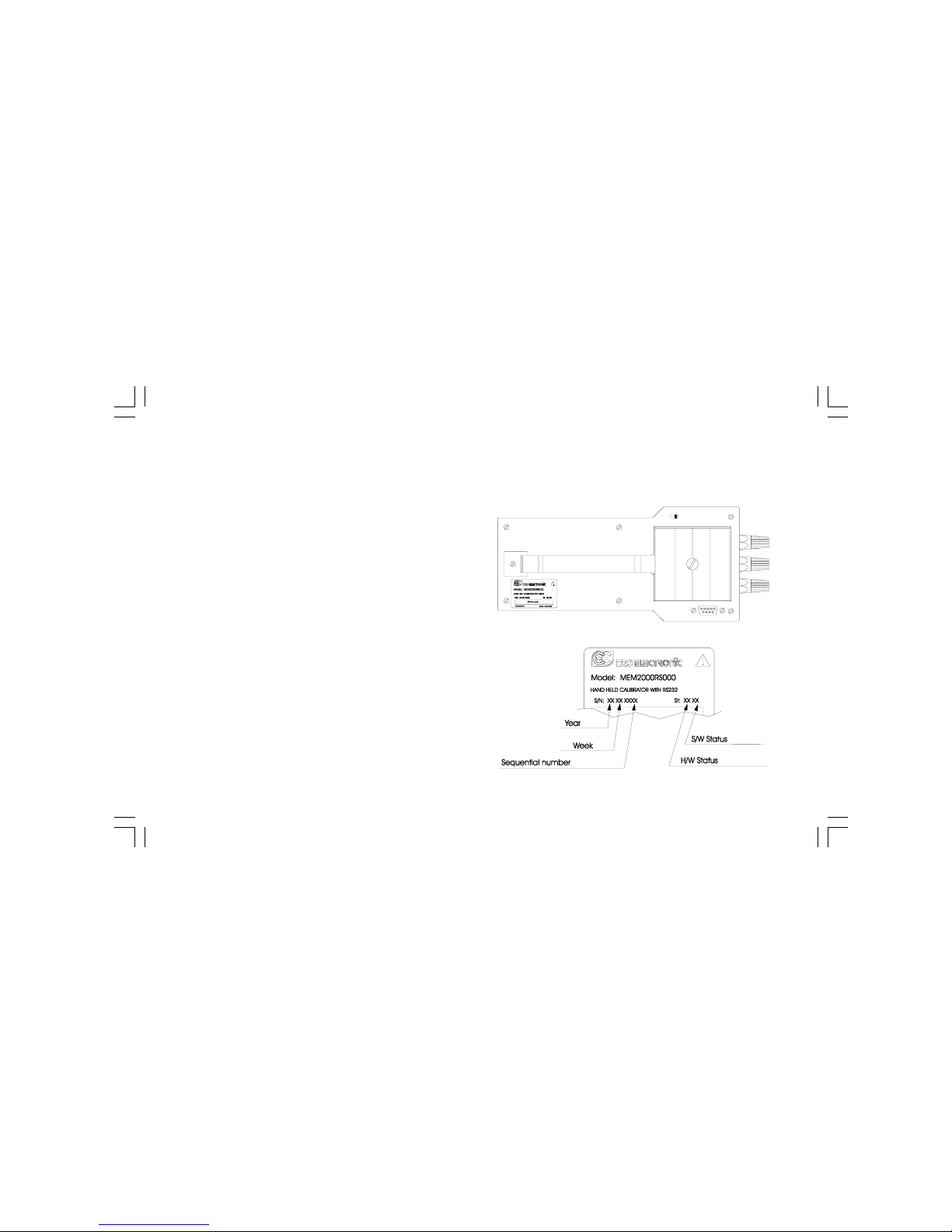
1.7 IDENTIFICATION LABEL
The instrument identification label is located externally on the housing.
It contains the following information:
M20-e-1.p65 7/9/01, 2:39 PM12
13
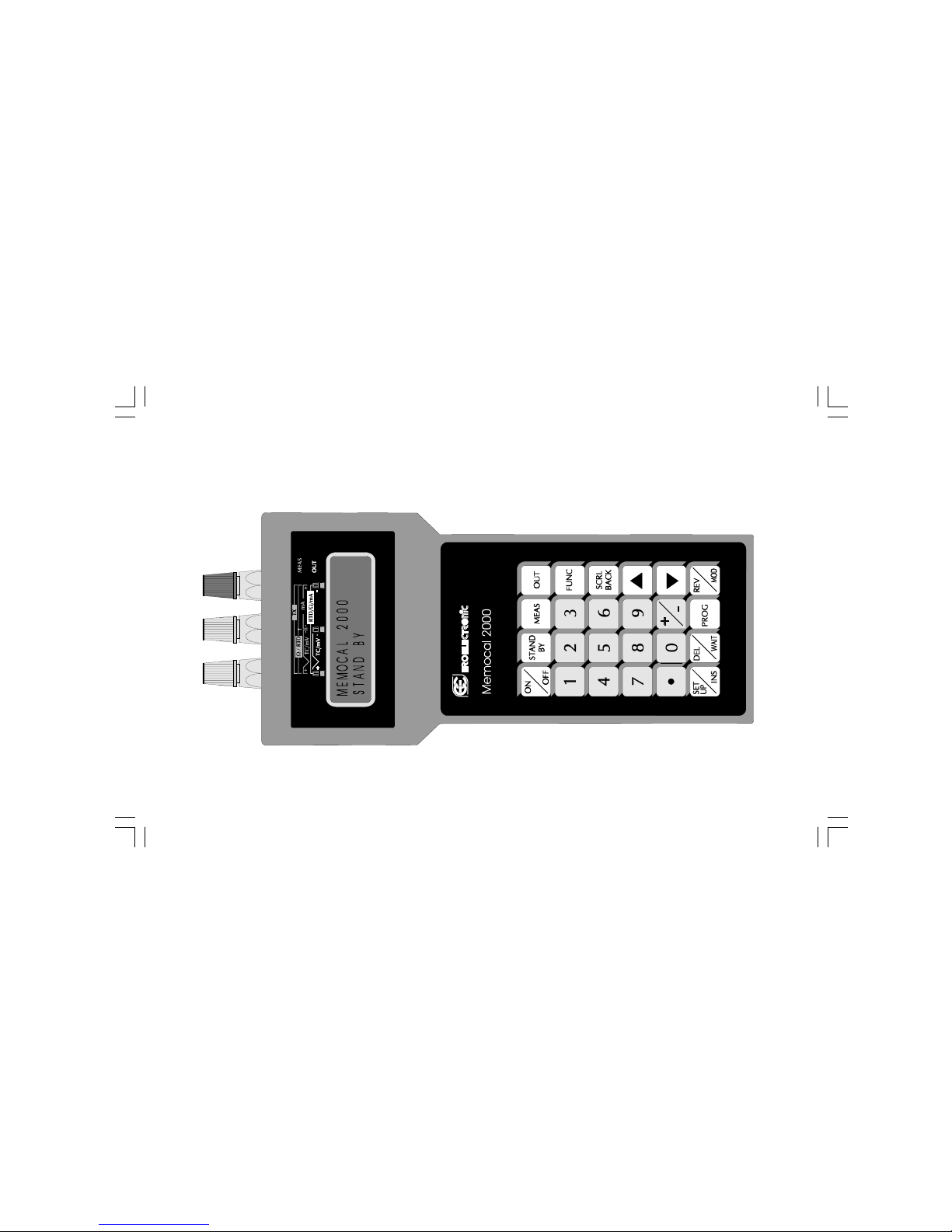
2.1 FRONT PANEL DESCRIPTION
SECTION 2 INSTRUMENT CONFIGURATION
M20-e-2.p65 7/9/01, 2:40 PM13

14
2.2 KEYBOARD DESCRIPTION
It allows to turn ON or OFF the instrument.
This key has 2 different functions:
1) When the instrument operates in NORMAL
DISPLAY MODE, a fast depression of the push-
button will turn ON or OFF the display
backlighting. The instrument has an internal 30
seconds time out, 3 sec only when battery is
"low". If no one of the push-buttons have been
depressed in the meantime, then the
backlighting will turn OFF automatically.
2) By keeping depressed this push-button for 1,5
seconds the instrument returns in
STAND BY mode.
It is used to start a measuring sequence.
It is used to start a generating sequence.
Push-button from to are used to set all the
numerical values.
It sets the sign of the numerical value (for numeri-
cal data entry in generation and for scalable values)
It inserts the decimal point (for numerical data entry
in generation and for scalable values).
During setting procedures, this key allows the
storage of the desired value or the desired menu
selection and then to step to the next parameter.
During program execution, this key allows to jump to
the next program step.
During setting procedures, it allows scrolling back
the menu selection without storage of settings.
During program execution, this key allows to jump
immediately to the previous program step.
During measurement, it is used to display the
maximum peak value.
By depressing it a second time, it toggles to the
normal measured value.
During generation, by keeping it depressed, it
M20-e-2.p65 7/9/01, 2:40 PM14

15
Used to select the desired program for running,
editing or deleting
During a scaled measurement or a scaled genera-
tion, it is used to revert the display from the
normalized value to the actual electrical value and
vice versa.
During program editing it is used to modify the
program.
This push-button is used for instrument set up.
During program editing, it inserts a new program
step.
+ During measurement, they allow to
clear the memory of the maximum peak
value.
+ During measurement, they allow to
clear the memory of the minimum peak
value.
+ During measurement, they allow to
clear both of the above.
2.3 INSTRUMENT CONFIGURATION
overimposes a ramp to the generated value with a
gradient of 1 LSD for each 1/2 second; by depress-
ing it once, the generated output will increase of 1
LSD.
During a selection procedure, it is used to move the
cursor forward.
During measurement, it is used to display the
minimum peak value.
By depressing it a second time, it toggles to the
normal measured value.
During generation, by keeping it depressed, it
overimpose a ramp to the generated value with a
gradient of 1 LSD for each 1/2 second; by depress-
ing it once, the generated output will decrease of 1
LSD.
During a selection procedure, it is used to move the
cursor backward.
During editing of a numerical value, it deletes the
typed value.
During program editing, it deletes the whole program,
a single step or a numerical value.
While a program is running, this push-button, once
depressed, enables/disables the WAIT function.
M20-e-2.p65 7/9/01, 2:40 PM15

16
At the first start up of the instrument or when it is desired to modify
a configuration parameter proceed as follows.
The instrument should be in STAND BY mode or in NORMAL
DISPLAY MODE.
Depress the SET UP/INS push-button. The display will show the
following:
This instrument is capable to performing, during TC and RTD
measurement, an open input test (the instrument injects a 100 mA
impulse signal).
When this test is desired, select YES and depress the FUNC push-
button.
The display will show:
Where :
SERIAL LINK
To enable the serial communication.
DIGITAL INP
To enable the logic inputs.
NONE
Both options are disabled.
2.3.1 SERIAL LINK
RS-232 connection diagram
Pin Description
1RESERVED
2 - RS232 receiver data (RX)
- Logic input 1 (step advance)
3 RS232 transmitter data (TX)
4 Positive voltage for logic input
5 Signal ground for RS232
6RESERVED
7 RTS Request to send (used by the RS 232/RS485
converter).
8 Logic input 2 (RUN/WAIT)
9RESERVED
OPEN INPUT TEST?
YES NO
SERIAL LINK
DIGITAL INP NONE
5 4 3 2 1
9 8 7 6
M20-e-2.p65 7/9/01, 2:40 PM16

17
WARNING: to avoid damage to the instrument, pin 1, 6 and 9 must
be ever disconnected (we suggest the use of the "connection cable
for PC" supplied with the instrument)
Selecting the SERIAL LINK and depressing the FUNC push-button,
the display will show the following:
where:
AD is the address of the serial communication interface (from 1
to 255 ).
BR is the communication baud rate (600, 1200, 2400, 4800,
9600, 19200).
XBUS Shows the desired communication protocol (MBUS = Mode
bus or JBUS = Jbus).
PA is the communication parity control (NONE, EVEN, ODD).
With the sor tpush-buttons modify the numerical values, while,
with FUNC push-button, go to the following field.
AD XX BR XXXXX
XBUS PA XXXX
2.3.2 DIGITAL INPUTS
WARNING: to avoid damage to the instrument, pin 1, 6 and 9 must
be ever disconnected.
DIGITAL INPUT 1
During a sequential function routine execution, when the instrument
detects a transition from OFF to ON of the logic input 1, it will stop
to execute the actual step and will start immediately to execute the
next step (STEP ADVANCE) of the selected sequential function
routine.
DIGITAL INPUT 2
During a sequential function routine execution, it allows to stop
(WAIT) or to continue (RUN) the routine execution.
When the logic input 2 is in ON condition, the routine execution is in
WAIT status.
When the logic input 2 is in OFF condition, the routine execution is
in RUN status.
8
4
OFF
ON
2
4
OFF
ON
M20-e-2.p65 7/9/01, 2:40 PM17

18
NOTE: when the logic inputs are selected, the WAIT function can
be enabled/disabled by logic input 2 only.
2.3.3 NONE
When NONE is selected no option will be used and the instrument
goes automatically to the next configuration step
After option selection and its parameter setting, the display will
show the following:
Select the desired default engineering unit.
Depressing the FUNC push-button.
The display will show the following:
Select the derired standard for TC and RTD measure and genera-
tion.
Depressing the FUNC push-button.
DEFAULT ENG.UNIT
°C °F
The configuration procedure is completed and the instrument will
memorize the new configuration parameters and goes automati-
cally to the STAND BY mode.
NOTE: It is possible to stop the configuration procedure in any
moment by pushing SET UP/INS pushbutton. The instrument will
memorize the new setting followed by FUNC pushbutton pressure
and it will use the old values for all the other parameters.
TEMP. STANDARD
IPTS-68 ITS-90
M20-e-2.p65 7/9/01, 2:40 PM18

19
4) RUN (it is running a routine).
5) EDIT (the user is editing a routine).
In the following pages each mode will be described completely.
3.1.2 GENERAL NOTES
1) The I/O impedance of the instrument will be equal to:
a) high impedance (>500 KOhm) for STAND BY mode, EDIT
mode, mV, V or TC measurement;
b) low impedance for mA measurement and Ohm simulation;
c) current injection for resistance or RTD measurement;
d) low impedance with 24 V power supply for TX measurement.
e) During RUN mode the I/O impedance will be in accordance
with the programmed action.
2) When the transfer from MEAS to OUT is requested, the
instrument goes automatically in STAND BY mode in order to
assure an high impedance during instrument connection.
3.1.3 GENERAL NOTES ON GENERATIONS
1) During generation, when a new value is desired, it is sufficient to
type directly the new value using the numerical keyboard and to
push the FUNC push-button. The instrument will start immedi-
ately to generate the new value.
2) By pushing sor tpush-button, the generated value will be
increased or decreased of 1 LSD.
3) By pushing continuously sor tpush-button, the generated
value will change with a rate equal to 2 LSD/second.
4) When, typing a value, an error occurs, push the DEL push-button
and retype the desired value.
SECTION 3 - OPERATING INSTRUCTIONS
3.1 PRELIMINARY
1) In order to assure the maximum accuracy of the instrument it is
necessary to perform a 3 minutes warm-up period before to start
to calibrate.
2) For all TC measurements and simulations and for mV measure-
ments and generations it is suggested to connect the cables
directly to the instrument connectors without any additional plug.
If plugs are required, it is necessary to use gold plated banana
plugs in order to avoid not desired junctions between the cables
and the plug material.
3) For all ranges, it is suggested to use No 20 AWG (0,597 mm2)
or larger wires.
3.1.1 OPERATIVE MODE
At power up, the instrument starts in stand by mode (warm-up with
low power consumption) and the display will show:
The instrument may be operative in one of the 5 following modes:
1) STAND BY (warm-up with low power consumption)
2) MEASURE (it is performing a measure)
3) GENERATION (it is performing a generation)
MEMOCAL 2000
STAND BY
M20-e-3.p65 7/9/01, 2:40 PM19

20
5) When a negative value is desired, it is possible to depress the [+/
-] push-button at any time during data entry procedure.
6) Setting a numerical value out of the selected range, the instru-
ment will show "E" and it will continue to generate the old value.
7) Setting a value with a number of decimal figures higher than the
selected range, the instrument will truncate the programmed
value according to the number of decimal figures of the selected
range.
8) When it is selected a generation with automatic range selection
and a value higher than 20000 counts is programmed (the
decimal point position have no influence), the instrument will
show the "E" message and it will continue to generate the old
value.
NOTE: only the OUT 20 mA NON RANGEABLE selection allows
to set a (and to generate) a value up to 21.000 mA.
GENERAL NOTES ON MEASUREMENTS
1) During a measurement, the maximum and minimum data hold
functions are enabled.
These functions are activated automatically by measuring
function.
To display the maximum and minimum data hold push, respec-
tively, the sand tpush-button.
The instrument will show, on the right hand of the value, the PKH
message when the maximum data hold value is shown or PKL
message when the minimum data hold is shown.
When it is desired to clear the values of the maximum or
minimum data hold previously memorized, push the DEL/WAIT
push-button and, maintaining the pressure, push, respectively,
the sor tpush-button.
2) The instrument incorporates, for mV, mA and TX measurements
with programmable scaling, a special function REV/MODE that
allows to display, temporaneously, the measured value without
scaling (in mV or mA).
To enable or disable this function push the REV/MODE push-
button.
M20-e-3.p65 7/9/01, 2:40 PM20
Table of contents
Other ero electronic Measuring Instrument manuals


