/ 7 www.ziehl.de
8 Installation
The unit can be installed as follows:
•Installation in switchgear cabinet on 35 mm mounting rail according to EN 60715
•With 2 screws M4 for installation on wall or panel
Connection according to connection plan.
9 Putting into operation
Parameterization of monitoring sensor errors (factory settings: monitoring sensor errors off )
•Power off the device
•Press button [Test] and keep pressed
•Power on the device, and keep pressed the button [Test]
➢After 5s blinks the green LED, release button [Test]
•Press Button [Test] again to switch the function
➢monitoring sensor errors on (red LEDs on)
➢monitoring sensor errors off
•Keep button [Test] pressed (2s) to save the function (the Power LED blinks fast, release
button [Test])
•The MSF220K makes a reset and restarts with the set function
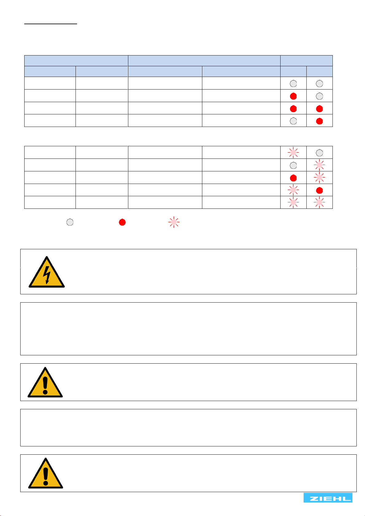
Checking the function of device
•Power on the device (green LED Power is on)
•The relay K1 switch on (Terminals 11-14 closed) and the red LEDs AL1 and AL2 are off
Function of button [Test] under operation
•Press button [Test] and keep pressed
•The green LED signals the status of monitoring sensor errors
➢monitoring sensor error on: LED blinks -> 2 x fast –pause - 2 x fast –pause - …)
➢monitoring sensor error off: LED blinks evenly
•after 5s: Alarm 1 becomes active (relay K1 = off, terminals 11-12 closed, red LED AL1 = on)
•after 8s: Alarm 2 becomes active (relay K2 = on, terminals 21-24 closed, red LED AL2 = on)
•release button [Test] to chancel the test function
Even if no temperature warning is monitored with alarm 1, the function of the relay K1 must be evaluated,
otherwise the monitoring can fail unnoticed (missing supply- voltage, equipment failure etc.).
Connect a resistor (0,1kΩ…1,5kΩ) to sensor input PTC 1 (T0-T1), also 0Ωif monitoring sensor error = off.
10 Troubleshooting and remedies
•LED Power is off
Make sure that supply voltage is connected correctly (+/-) to terminals A1/A2 and
correspond with the voltage on type plate
•Alarm 1 / Alarm 2 always active (LED AL1 / AL2 is on)
Make sure, that the PTCs are correct connected and the voltage at the terminals is <
DC 0,8 V. The resistance of the PTCs in cold state should be < 1,5 kΩ.
Check PTC’s only with measuring voltages of < 2.5 V.
•LED Power blinks and Alarm 1 is active (button Test is not pushed, not at parameterization)
internal device error, switch it off and on. If the error persists please replace device.
Send in together with a description of the occurred malfunction.
•Alarm 1 constantly active (K1 off, 11-12 on) and at least one alarm LED blinks:
monitoring sensor error active, check sensors for short circuit and interruption
monitoring sensor error in PTC 1 (AL1 blinks) and/or sensor error in PTC 2 (AL2
blinks)