4
INTRODUCTION
All objects with a temperature above absolute zero emit electromagnetic radiation. The wavelengths and
intensity of radiation emitted are related to the temperature of the object. Terrestrial surfaces (e.g., soil,
plant canopies, water, snow) emit radiation in the mid infrared portion of the electromagnetic spectrum
(approximately 4-50 µm).
Infrared radiometers are sensors that measure infrared radiation, which is used to determine surface
temperature without touching the surface (when using sensors that must be in contact with the surface, it
can be difficult to maintain thermal equilibrium without altering surface temperature). Infrared
radiometers are often called infrared thermometers because temperature is the desired quantity, even
though the sensors detect radiation.
Typical applications of infrared radiometers include plant canopy temperature measurement for use in
plant water status estimation, road surface temperature measurement for determination of icing
conditions, and terrestrial surface (soil, vegetation, water, snow) temperature measurement in energy
balance studies.
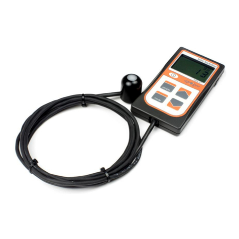
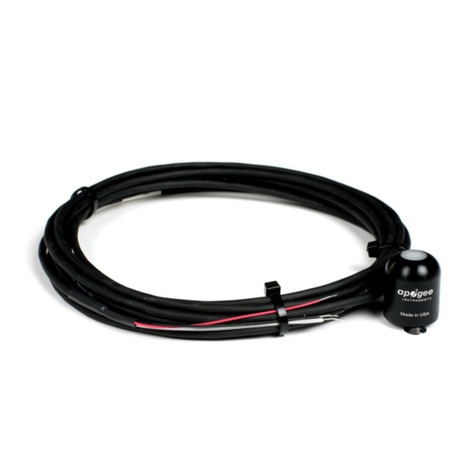
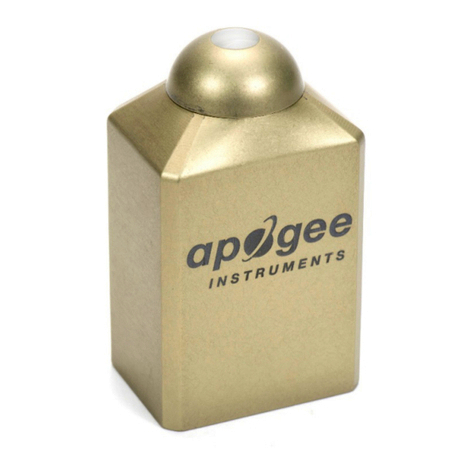
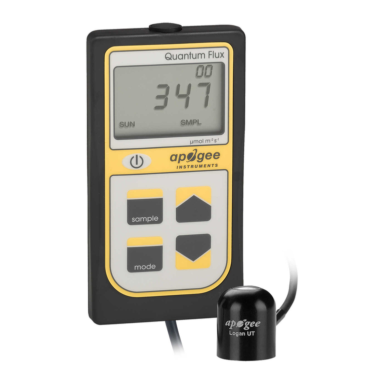
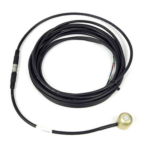
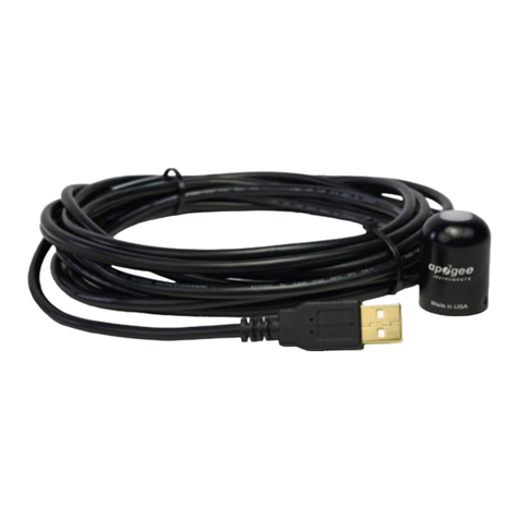
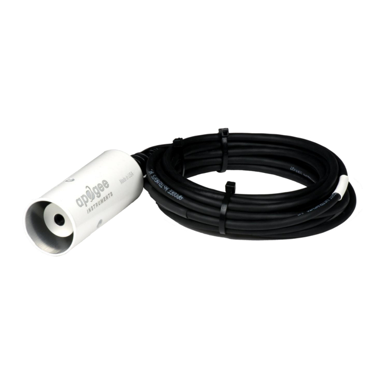
Apogee Instruments SI series infrared radiometers consist of a thermopile detector, germanium filter,
precision thermistor (for detector reference temperature measurement), and signal processing circuitry
mounted in an anodized aluminum housing, and a cable to connect the sensor to a measurement device.
All radiometers also come with a radiation shield designed to minimize absorbed solar radiation, but still
allowing natural ventilation. The radiation shield insulates the radiometer from rapid temperature
changes and keeps the temperature of the radiometer closer to the target temperature. Sensors are
potted solid with no internal air space and are designed for continuous temperature measurement of
terrestrial surfaces in indoor and outdoor environments. SI-400 series sensors output a digital signal using
SDI-12 protocol version 1.3.
