EROAD Clarity Dashcams User manual
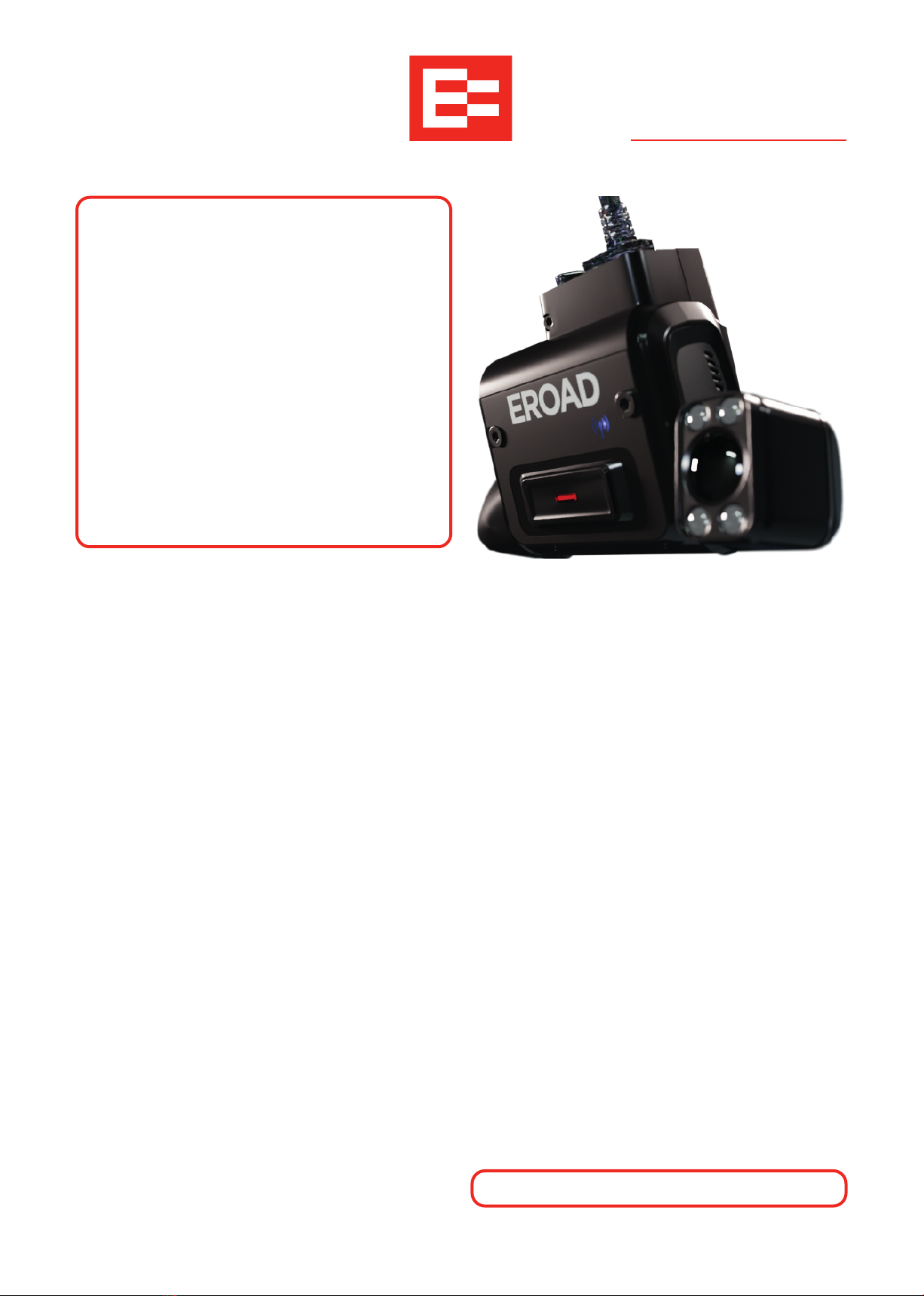
EROAD
Clarity Dashcams
Installation Guide
IMPORTANT
The packaging has a QR code
necessary for registration, and it may
contain smaller, overlooked items.
Do not discard until the installation
is complete.
This Guide contains several similar
install types for the same unit.
Each type is color-grouped. Consider
reducing the potential for confusion
by physically removing irrelevant
types from this document prior to
installation.
Clarity Solo Kit (STD)
»Main power cable
»MicroSD card (pre-installed)
»ATOF 32V / 2A blade fuses x2
»Fuse holders x2
»Lens covers x2
»Cable ties x2
HR003108A Windshield kit
»Windshield mounting plate (with adhesive pad)
»Cleaning wipe
»Allen/Hex key (2mm)
»EROAD Windshield sticker
»I/O Port guard
Clarity Connected Kit
»Everything in STD, + Windshield Kit, AND:
»HR003101A 3-wire loom (No GPIOs), or
»HR003100A loom, GPIO-ready, or
»HR003105A loom, GPIO-ready, and/or
»ECM Y-cable
GPIO Remote Record Button kit
(HR003107A)
»Remote Record button 2-wire attachment
»Button O-ring
»Mounting washer
»Mounting nut
»Cable ties x2
»ATOF 32V / 2A blade fuse
»Fuse holder
GPIO Remote Record button kit
(HR003106A)
»Remote Record button 2-wire connector
»12-2 wire loom
»Button O-ring
»Mounting washer
»Mounting nut
»Cable ties x2
»ATOF 32V / 2A blade fuse
»Fuse holder
There are no user-serviceable parts.
2
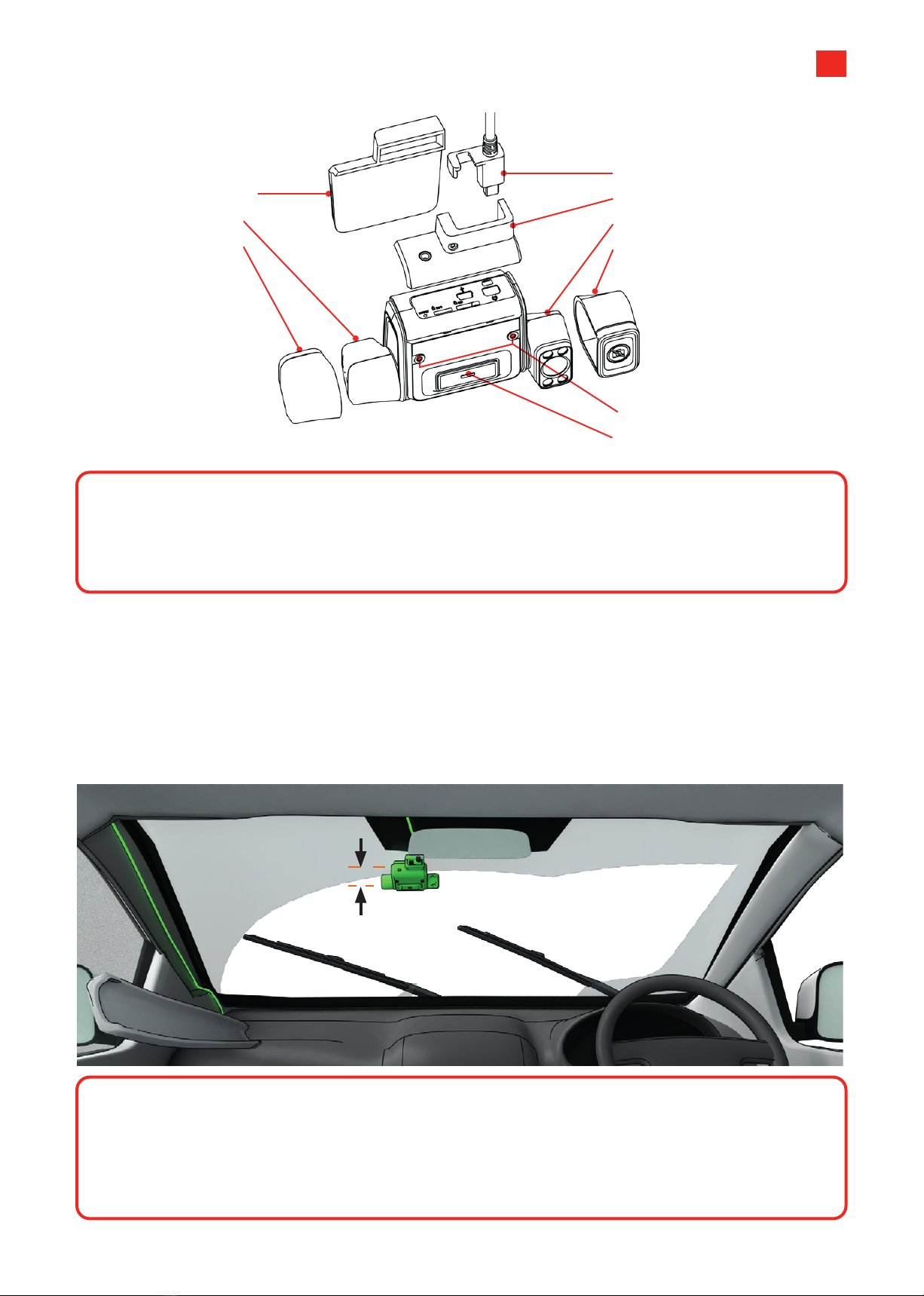
Dashcam Parts
1 Windshield
mounting plate
2 Road camera
3 Road lens cap
8 Camera locking bolts
9 Manual record
4 Cable Insert + cable
5 I/O Port guard
6 Cab camera
7 Cab lens cap
CAUTION
The Clarity cameras each have a RESTRICTED RANGE OF ROTATION. Do NOT
attempt to rotate them with the locking bolts tightened, or past their tolerance limits
(approximately90° rotation for each camera).
Placement
Position the dashcam inside, in the approximate
middle-top of the windshield, or if this location is
already occupied, slightly passenger-side.
The front camera should be approximately 8
inches (20 cm) below the windshield wipers'
highest sweep-point.
The unit should be mounted outside the driver’s
normal sight lines of the road ahead, highway signs,
signals and all mirrors.
20 cm / 8 in
CAUTION
Assuming a "one way fits all" approach to fleet installation is dangerous.
Dierent cabs have dierent windshield angles, cab configurations, wiper-blade positions
and concerns around left/ right/ dual seating.
It's important that you treat each cab with individual attention to detail.
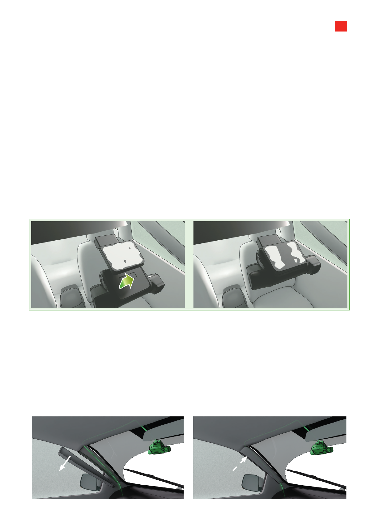
Fig. 1 Fig. 2
A-Pillar Cover
Fig. 3
A-Pillar Cover
Fig. 4
3
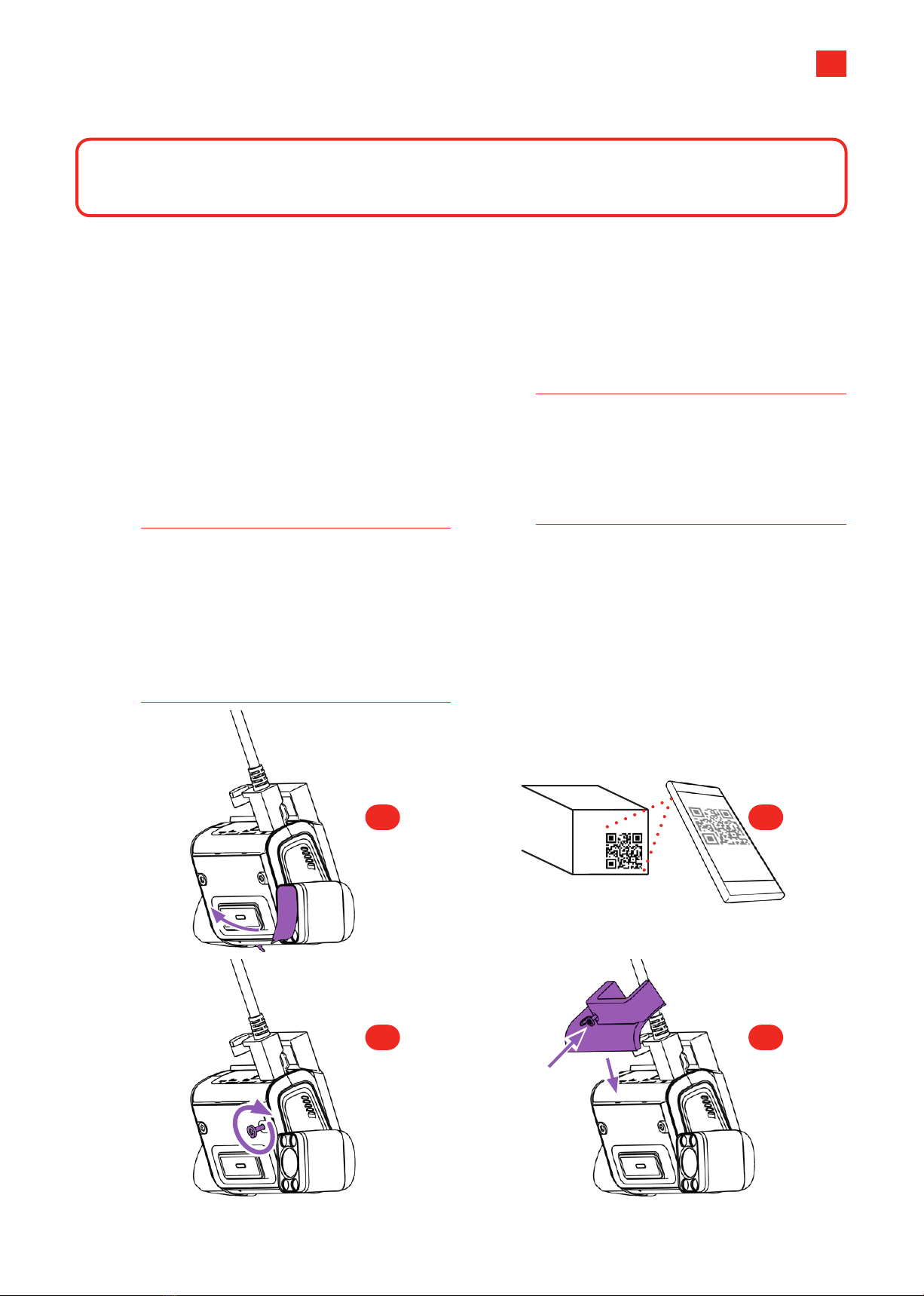
Mounting the Dashcam
1 Clean the mounting area with the alcohol
wipe provided.
2 Re-wipe the area with a clean cloth to remove
any residue.
3 Remove the adhesive paper from the
mounting plate.
4 Alignment check:
»Ensure the pad orientation will hold the
dashcam with the cable facing UP.
»The road-facing camera must not be blocked
by existing ADAS units, toll tags, tints or
sunshades, vehicle certifications, other decals
or objects.
»The cab-facing camera should not be blocked
by mirrors, internal shades or hanging items.
»The mounting plate is level with the horizon.
5 Press the MIDDLE of the mounting plate firmly
into the windshield, working outwards, so the
entire adhesive pad touches the windshield
(you can better check this occasionally from
outside the vehicle). Push firmly for 20s. Wait
another 2 minutes for full adhesion.
6 Attach the dashcam body into the mounting
plate. Leave the protective film on the lenses
until the Install Wizard phase.
Fig.1: CORRECT Full contact with the mounting
plate to the windshield. THEN, the main body
is mounted.
Fig. 2: INCORRECT Dashcam should be mounted
AFTER the mounting plate has fully stuck to the
windshield.
7 Plug the main cable into the dashcam. The
cable should run:
»Across the top of the windshield out of sight.
»Down the windshield's A-pillar (out of sight,
secured, tucked into the lining trim), down
the back of the dashboard.
»In the shortest, most convenient path to your
key connection points.
8 Find the vehicle’s junction and/or fuse box
under the dash. It’s good practice to take a
picture of the vehicle’s current configuration to
use as a reference later.
9 If attaching the Remote Record button, be
aware that this can be fused on a separate
circuit for vehicle power, or run o an existing
fused power circuit.
Fig. 3: A-pillar removal. A-Pillar linings use a snap-in clip, and are removable by hand. Remove, run the
cable down its length, and replace (Fig. 4).
4
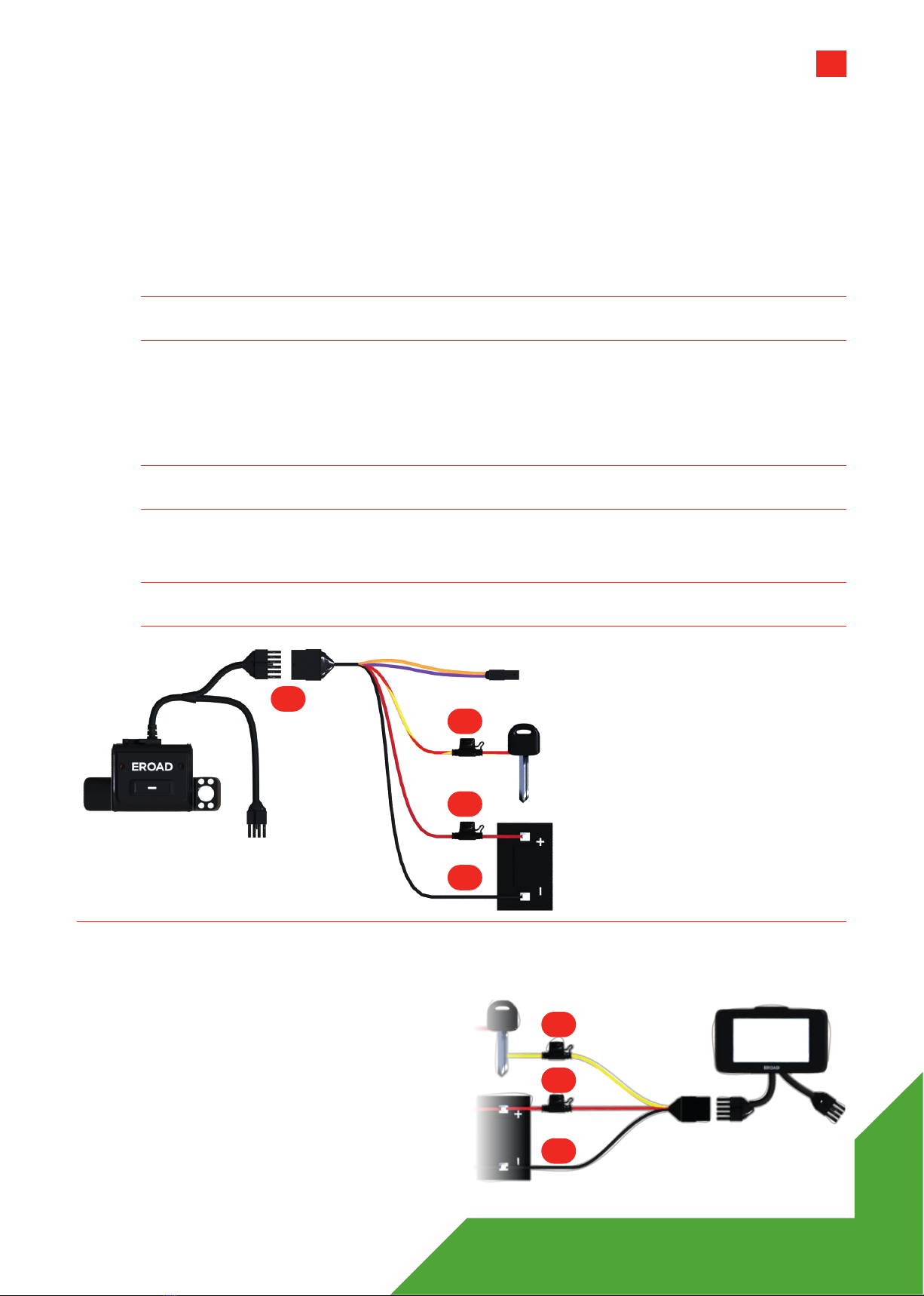
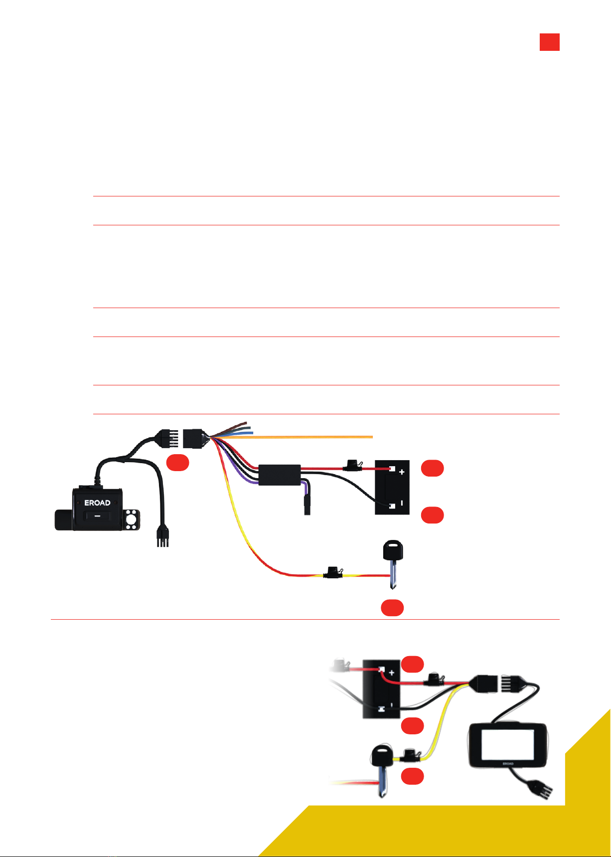
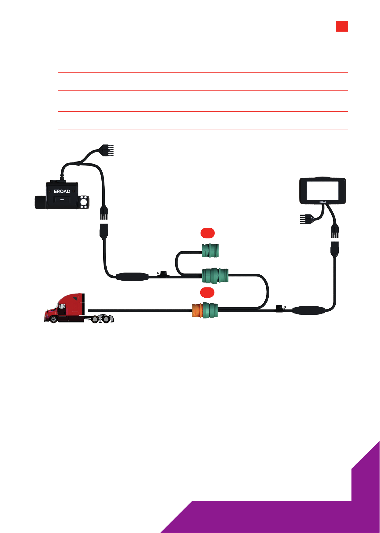
3-wire Install Using the HR003101A Loom
The diagram shows a basic connection for the Clarity Connected and Clarity Solo dashcams using the
HR003101A 3-wire loom along with a basic Ehubo wiring diagram. If you are installing a Clarity Connected
camera, your Ehubo is likely to be fused and connected already.
»RED wire fused to vehicle DC power.
»YELLOW/RED wire fused to Ignition.
»BLACK wire to Ground.
Note 1 Always seal wiring connections with heat shrink and/or electrician's tape.
Do not cut cables - Coil and tie them out of the way.
1 Connect the 12-way connector from the Dashcam to the 12-way connector on the 12-way wiring loom.
Secure with electrical tape.
2 Connect the BLACK wire on the 12-way wiring loom to an appropriate grounding location.
3 Connect the RED wire on the 12-way wiring loom to a permanent power source.
Note 2 Ensure there is a constant 12-24V when the key is inserted, with the engine running, and also
when the key is not inserted and the engine is o.
4 Connect the RED/YELLOW-striped wire on the 12-way wiring loom to an ignition/switched
power source.
Note 3 Ensure the ignition/switched power source supplies 12-24V when the key is in the ON position
and zero volts when the key is in the accessory (ACC) and OFF positions.
Dashcam Connected Only
Consult the dedicated Ehubo Installation Guide for
full instructions. But as a wiring check:
1 Connect the BLACK wire on the 10-way wiring
loom to an appropriate grounding location.
2 Connect the RED wire on the 10-way wiring
loom to a permanent power source.
3 Connect the YELLOW wire on the 10-way wiring
loom to an ignition/switched power source.
4 See all notes above.
10-way
Connectors
12-way
Connectors
8-way
Connector
(unused)
Ignition
Power
12-24V
DC Power
GND/
Return
3106: 3-WIRE, NO GPIOS3106: 3-WIRE, NO GPIOS
1
3
2
3
4
1
2
5
3106: 3-WIRE, NO GPIOS3106: 3-WIRE, NO GPIOS
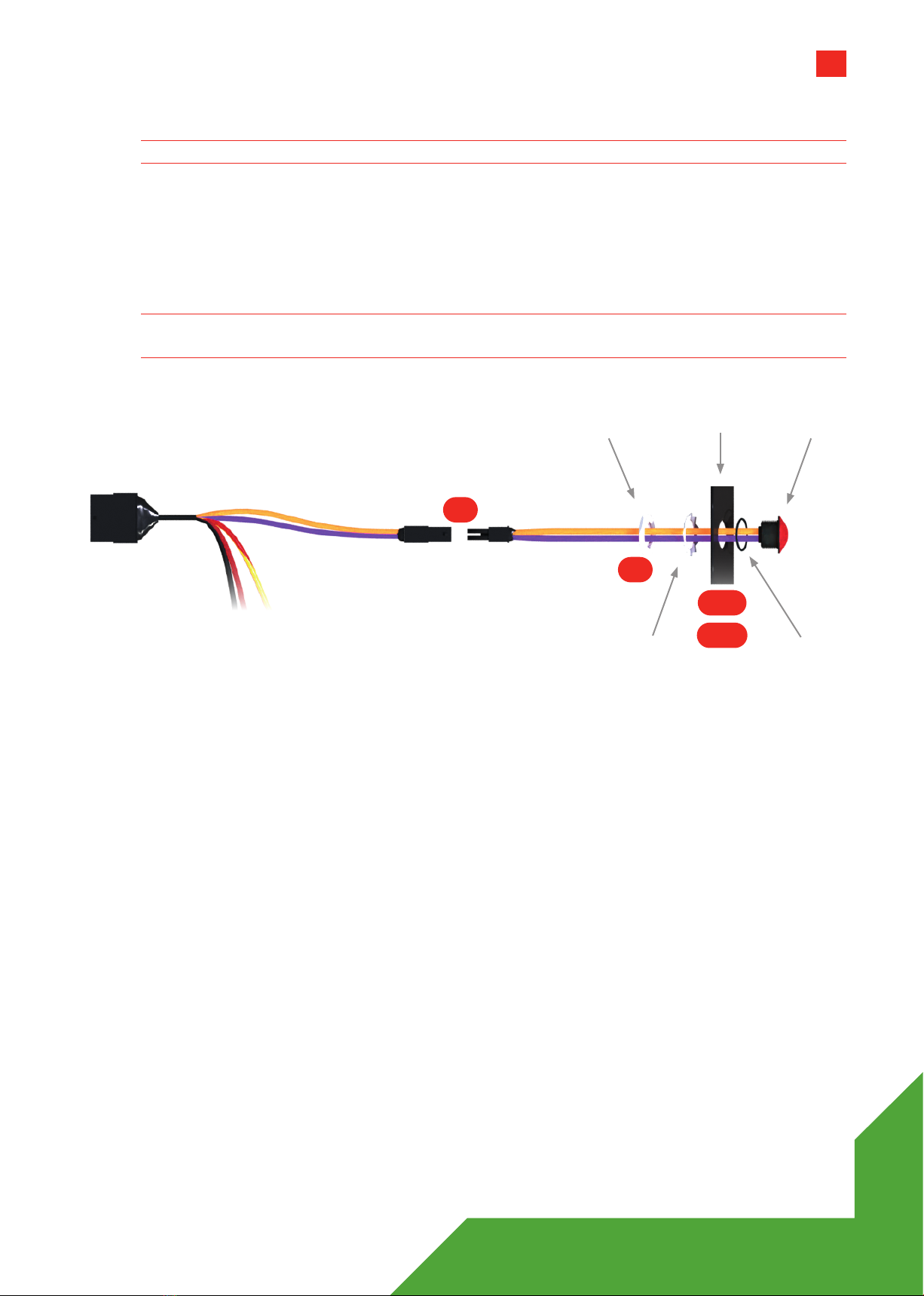
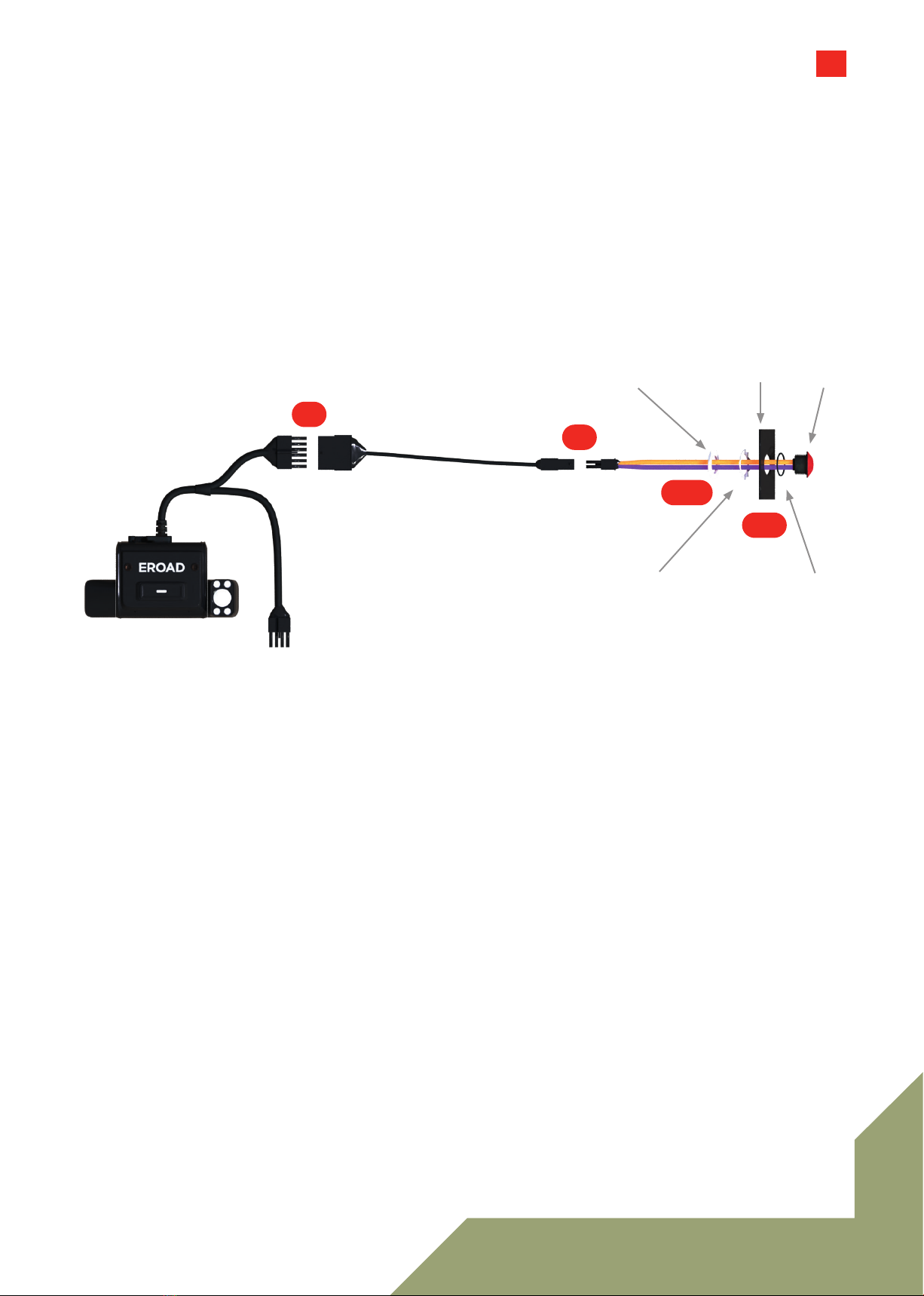
Remote record button install (HR003106)- Optional
Note 4 The 12-2 wire loom that comes with this remote button kit IS NOT USED for this install.
1 Drill a 14mm (0.55in) diameter hole into a dashboard panel (or similar site within comfortable reach of
the driver).
2 Ensure the O-ring remains near the head of the button-thread while removing the nut and washer.
3 Thread the wires through the washer and nut.
4 Connect the 12-way wiring loom to the Remote Record button, using the 2-way connectors provided.
Note 5 Ensure there is a constant 12-24V when the key is inserted, with the engine running, and also
when the key is not inserted and the engine is o.
5 Tighten the nut and washer.
6 Use cable ties to coil and tie away any excess cable. Button
O-Ring
Dash Panel
Washer
Nut
HR003101A 12-WAY PIN-OUT
1 GPIO input 1 Orange
2 Not Connected
3 +ve power in Red
4 Not Connected
5 Not Connected
6 Not Connected
7 Ignition Yellow/Red
8 Not Connected
9 Not Connected
10 Ground Black
11 +ve power out Purple
12 Not Connected
2-WAY CONNECTOR PIN-OUT
1 +ve power out Purple
2 GPIO1, input 1 Orange
HR003101A
12-way
Connector
2-way
Connectors 1-2
5,6
4
3
6
3100: 3-WIRE, WITH GPIOS3100: 3-WIRE, WITH GPIOS
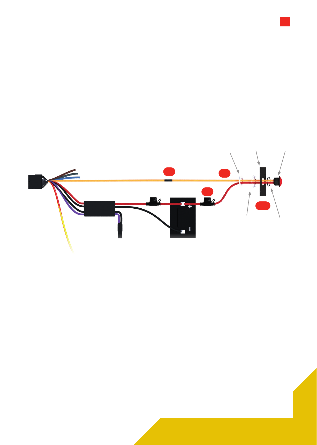
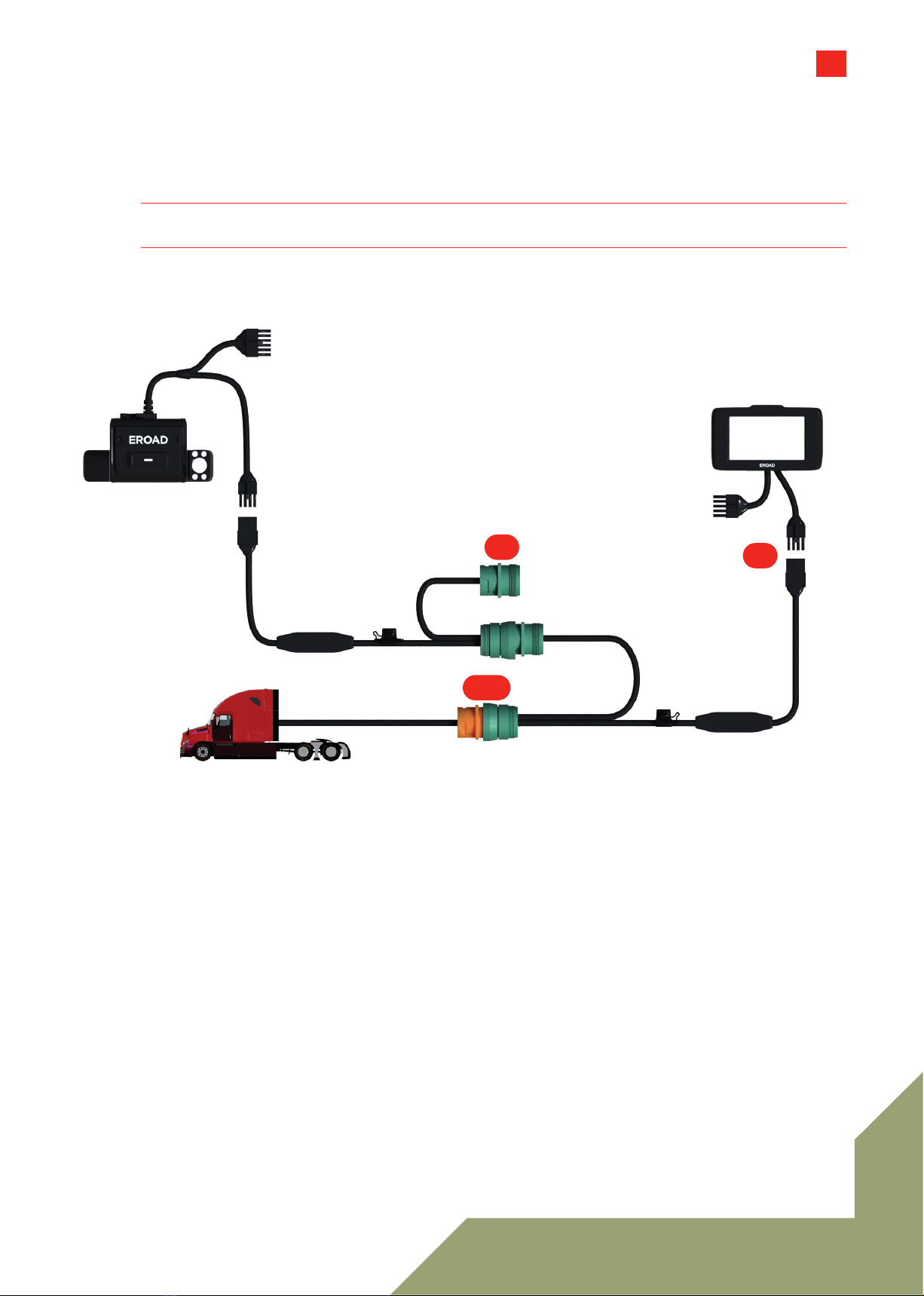
3-wire Install Using the HR003100A Loom (GPIO)
The diagram shows a basic connection for the Clarity Connected and Clarity Solo dashcams using
the HR003100A 12-wire loom along with a basic Ehubo wiring diagram. If you are installing a Clarity
Connected camera, your Ehubo is likely to be fused and connected already.
»Red wire fused to vehicle DC power.
»Yellow wire fused to Ignition.
»Black wire to Ground.
Note 6 Always seal wiring connections with heat shrink and/or electrician's tape.
Do not cut cables - Coil and tie them out of the way.
1 Connect the 12-way connector from the Dashcam to the 12-way connector on the 12-way wiring loom.
Secure with electrical tape.
2 Connect the BLACK wire on the 12-way wiring loom to an appropriate grounding location.
3 Connect the RED wire on the 12-way wiring loom to a permanent power source.
Note 7 Ensure there is a constant 12-24V when the key is inserted, with the engine running, and also
when the key is not inserted and the engine is o.
4 Connect the RED/YELLOW-striped wire on the 12-way wiring loom to an ignition/switched
power source.
Note 8 Ensure the ignition/switched power source supplies 12-24V when the key is in the ON position
and zero volts when the key is in the accessory (ACC) and OFF positions.
Dashcam Connected Only
Consult the dedicated Ehubo Installation Guide for
full instructions. But as a wiring check:
1 Connect the BLACK wire on the 10-way wiring
loom to an appropriate grounding location.
2 Connect the RED wire on the 10-way wiring
loom to a permanent power source.
3 Connect the YELLOW wire on the 10-way wiring
loom to an ignition/switched power source.
4 See all notes above.
12-way
Connectors
10-way
Connectors
8-way
Connector
(unused)
GND/
Return
Ignition
Power
12-24V
DC Power
1
2
4
3
1
2
3
7
3107: REMOTE BUTTON3107: REMOTE BUTTON
Remote record button install (Kit HR003107A) - Optional
1 Drill a 14mm (0.55in) diameter hole into a dashboard panel (or similar site within comfortable reach of
the driver).
2 Ensure the O-ring remains near the head of the button-thread while removing the nut and washer.
3 Thread the wires through the washer and nut.
4 Wire up the ORANGE wire from the 12-way wiring loom to the to the ORANGE wire on the
Remote Record button.
5 Fuse the RED wire to a permanent power source.
Note 9 Ensure there is a constant 12-24V when the key is inserted, with the engine running, and also
when the key is not inserted and the engine is o.
6 Tighten the nut and washer.
7 Use cable ties to coil and tie away any excess cable.
Button
O-Ring
Dash Panel
Washer
Nut
HR003100A 12-WAY PIN-OUT
1 GPIO1, input 1 Orange
2 GPIO2, input 2 Brown
3 +ve power in Red
4 RS232_RX Black/White
5 RS232_TX White
6 GPIO3, input 3 Grey
7 Ignition Yellow/Red
8 GPIO4, output 4 Blue
9 Not Connected
10 Ground Black
11 +ve power out Purple
12 Ground Black
2-WAY CONNECTOR PIN-OUT
1 GPIO1, input 1 Purple
2 GPIO2, input 2 Black
REMOTE BUTTON PIN-OUT
1 +ve power out Red
2 GPIO1, input 1 Orange
HR003100A
12-way
Connector
12-24V
DC Power
1-2
43
5
8
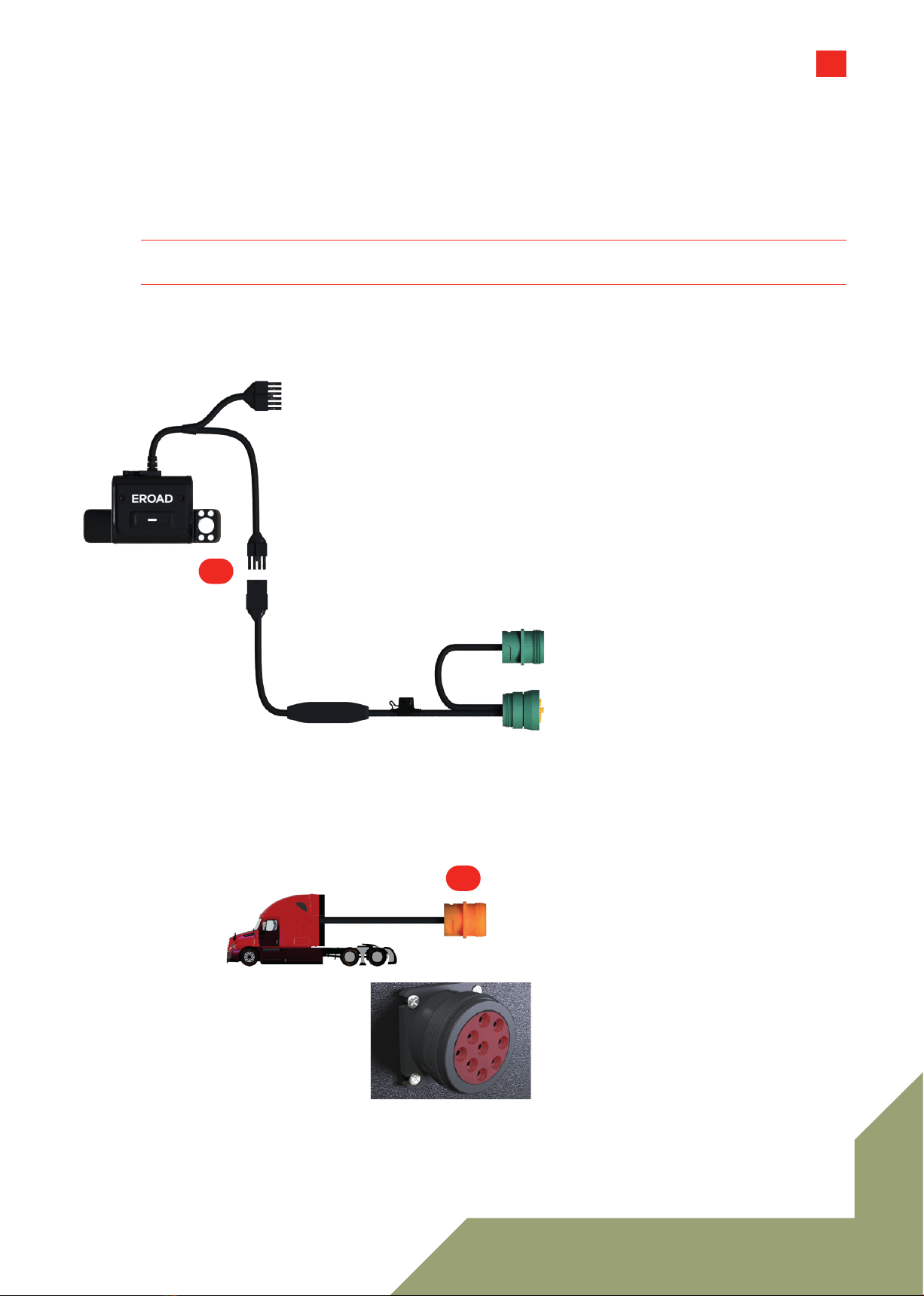
Hybrid ECM Install Using the HR003105A Loom (GPIO)
The diagram shows a basic connection for the Clarity Connected and Clarity Solo dashcams using
the HR003105A 12-wire loom along with a basic Ehubo wiring diagram. If you are installing a Clarity
Connected camera, your Ehubo is likely to be fused and connected already.
»Power and ground is obtained from the vehicle's diagnostic port.
»YELLOW/RED wire wire fused to Ignition.
Note 10 Always seal wiring connections with heat shrink and/or electrician's tape.
Do not cut cables - Coil and tie them out of the way.
1 Connect the 12-way connector on the main camera power cable to the 12-way connector on the 12-way
wiring loom. Secure with electrical tape.
2 Connect the RED and YELLOW striped wire on the 12-way wiring loom to an ignition/switched
power source.
3 Connect the 8-way connector on the main dashcam power cable to the 8-way connector on the
dashcam ECM Y-cable. Secure with electrical tape.
4 Locate the vehicle diagnostic port. This female connector will likely be built into a panel, and is typically
found under the dash on the driver side, in the fuse panel, or behind a removable dash panel.
(Vehicle diagnostic port
may be any color.)
12-way
Connectors
8-way
Connectors
ECM Y-cable
Ignition
Power
3105: HYBRID ECM WITH GPIOS3105: HYBRID ECM WITH GPIOS
1
2
3
4
9
3105: HYBRID ECM WITH GPIOS3105: HYBRID ECM WITH GPIOS
5 Unless this attached cable is another ECM Y-cable, detach it. If it is a Y-cable you could tap on to its
free end and continue the chain. Insert the dashcam ECM Y-cable onto the free end of the existing ECM
Y-cable. Ensure the cables are twist-locked and/or secured firmly.
Note 11 For Solo, the second Y-cable may not exist if there is no other hardware connected to the
vehicle's diagnostic port.
6 Mount the last free female connector back into the vehicle diagnostic port.
Note 12 Ensure the ignition/switched power source supplies 12-24V when the key is in the ON position,
and zero volts when the key is in the accessory (ACC) and OFF positions.
(This diagram shows the ECM
Y-cable daisy chain only.)
HR003105A 12-WAY PIN-OUT
1 GPIO1, input 1 Orange
2 GPIO2, input 2 Brown
3 Not Connected
4 RS232_RX Black/White
5 RS232_TX White
6 GPIO3, input 3 Grey
7 Ignition Yellow/Red
8 GPIO4, output 4 Blue
9 Not Connected
10 Not Connected
11 +ve power out Purple
12 Ground Black
2-WAY CONNECTOR PIN-OUT
1 GPIO1, input 1 Purple
2 GPIO2, input 2 Black
10-way
Connector
ECM Y-cable (1)
ECM Y-cable (2)
5
6
10
Remote record button install (Kit HR003107A) - Optional
1 Drill a 14mm (0.55in) diameter hole into a dashboard panel (or similar site within comfortable reach of
the driver).
2 Ensure the O-ring remains near the head of the button-thread while removing the nut and washer.
3 Thread the wires through the washer and nut.
4 Wire up the ORANGE wire from the 12-way wiring loom to the ORANGE wire on the Remote
Record button.
5 Fuse the RED wire to a permanent power source.
Note 13 Ensure there is a constant 12-24V supply when the key is inserted, with the engine running, and
also when the key is not inserted and the engine is o.
6 Tighten the nut and washer.
7 Use cable ties to coil and tie away any excess cable.
Button
O-Ring
Dash Panel
Washer
Nut
HR003105A
12-way
Connector
12-24V
DC Power
(This diagram does NOT show
the ECM chain associated with
this install type.)
3107: HYBRID ECM BUTTON3107: HYBRID ECM BUTTON
1-3
6,7
45
11
FULL ECM, NO GPIOSFULL ECM, NO GPIOS
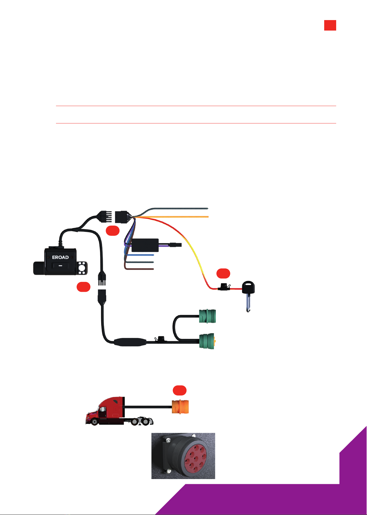
Full ECM Install (non GPIO)
The diagrams show a basic connection for the Clarity Connected and Clarity Solo dashcams using a full
ECM connection. A basic Ehubo wiring diagram is also shown. If you are installing a Clarity Connected
camera, your Ehubo is likely to be fused and connected already.
»Power, ground and ignition are obtained from the vehicle's diagnostic port.
Note 14 Always seal wiring connections with heat shrink and/or electrician's tape.
Do not cut cables - Coil and tie them out of the way.
1 Connect the 8-way connector on the main dashcam power cable to the 8-way connector on the
dashcam ECM Y-cable. Secure with electrical tape.
2 Locate the vehicle diagnostic port. This female connector will likely be built into a panel, and is
typically found under the dash on the driver side, in the fuse panel, or behind a removable dash panel.
(Vehicle diagnostic port
may be any color.)
12-way
Connector
8-way
Connectors
ECM Y-cable
1
2
12
FULL ECM, NO GPIOSFULL ECM, NO GPIOS
3 Unless this attached cable is another ECM Y-cable, detach it. If it is a Y-cable you could tap on to its free
end and continue the chain.
4 Insert the dashcam ECM Y-cable onto the free end of the existing ECM Y-cable. Ensure the cables are
twist-locked and/or secured firmly.
Note 15 For Solo, the second ECM Y-cable may not exist if there is no other hardware connected to the
vehicle's diagnostic port.
5 Dashcam Connected Only: Connect the ECM Y-cable to the 8-way Ehubo connection.
6 Mount the last free female connector back into the vehicle diagnostic port.
12-way
Connector
10-way
Connector
ECM Y-cable (1)
ECM Y-cable (2)
8-way
Connectors
8-way
Connectors
3,4
5
6
13
FULL ECM, BUTTONFULL ECM, BUTTON
Remote Record Button install (Kit HR003106A) - Optional
1 Drill a 14mm (0.55in) diameter hole into a dashboard panel (or similar site within comfortable reach of
the driver).
2 Connect the 12-way connector on the main camera power cable to the HR003106A Kit (12-to-2 wire
loom). Secure with electrical tape.
3 Ensure the O-ring remains near the head of the button-thread while removing the nut and washer.
4 Thread the wires through the washer and nut.
5 Connect the 2-way connectors from the HR003106A Kit. Secure with electrical tape.
6 Tighten the nut and washer.
7 Use cable ties to coil and tie away any excess cable.
Button
O-Ring
Dash Panel
Washer
Nut
HR003106A
12-way
Connector
2-way
Connectors 1,6
2
3,4
5
14
Install Wizard
IMPORTANT
These steps are required and Clarity will not operate correctly without them.
You need a mobile phone or tablet with a camera,
an active Internet connection, and QR code
scanning software (Apple devices can use the
Photo application) to complete these steps.
1 Check that your dashcam mounting location
and alignment meets regulatory requirements,
local regulations and related company policies.
2 Remove the protective film from BOTH of the
dashcam's lenses.
3 Scan the QR code (on the box in which the
dashcam was packaged) with your mobile
device to open the Install Wizard.
Note 16 If unable to use QR codes, go to:
https://install.eroad.com.
Open a browser on your mobile device
and type the dashcam's serial number
into the displayed field. The serial number
is printed on the packaging box after
"S/N".
4 Follow the step-by-step procedure in the Install
Wizard to ensure:
»the unit is provisioned correctly
»the cameras are aimed for optimal
coverage, and;
»the Record button(s) operate correctly.
Note 17 When evaluating the road-facing camera
please ensure that you have good
visibility of the surrounding front hood of
the vehicle and of the upcoming horizon.
Best practice is to incorporate fender
mirrors if possible.
5 Tighten BOTH the camera locking bolts.
6 Once the unit has passed its tests, attach the
I/O port guard to the mounted unit using an
Allen key. This screw secures the port guard and
the mounting pad together with the main body.
2 3
5 6

15
Photo confirmation
Photo document your work to assist in supporting
work order documents and proof of regulatory
compliance. Any digital camera may be used for 2
or 3 images per site, but images must:
»Show the unit clearly, mounted in place,
oriented appropriately.
»Show connections and wiring secure and tidily
managed. (The main dashcam cable should be
hidden behind cab trim.)
»Indicate the environment in which the device is
installed (its position in the cab).
Note the vehicle make/model for future reference.
NOTE
Photos are evidence of a compliant install. They protect EROAD and the Installer’s liability if a
future 3rd party alteration or incident aects compliance integrity.
General Purpose In/Out (GPIO)
GPIO looms are sets of wires with specific
purposes: power or signals. They may be used to
route data from, or power to, a variety of sensors
for seatbelts, brakes, indicators, thermostats,
windshield wipers, etc.
Please review the pin-out tables provided carefully
before attempting to wire up a loom.
A full pin-out appears with every instruction set,
but notable GPIO inputs include the BROWN and
GREY wires.
The BLUE wire is the only GPIO output.
The overmold diode board takes the two +ve
power conductors and two ground connections to
control the current direction.
About Engine Control
Modules (ECMs)
The ECM is the hub of a network of controllers
(sensors, winches, power modules, etc) operating
over a Controller Area Network, or CAN.
The ECM Y-cable lets you to add more controllers
to your CAN by daisy-chaining them together.
ECM connectivity isn’t essential for Clarity to
operate. Power can be sourced through wiring the
appropriate loom pin-out to 12VDCpower.

16
Safety & Best Practices
CAUTION
If installing this equipment on an unfamiliar vehicle, consult the vehicle's manufacturer
specifications beforehand.
»Before installation, check that other safety-
relevant equipment is working properly and
report any issues immediately.
»EROAD expects installers and contractors
to understand and follow all relevant health
and safety regulatory requirements, as
well as customer and relevant third party
requirements.
»Wear appropriate Personal Protective
Equipment (PPE) for the install risk and
customer requirements. Appropriate PPE
may include safety glasses, safety shoes, work
gloves, hard hat, high visibility vest, sun cream,
sun hat and/or coveralls.
»Avoid positioning EROAD equipment in
locations that could impede normal operation
or cause injury to people. This includes
potential head strike zones on the windshield
or dashboard, airbag deployment locations,
seatbelts, and other safety-relevant devices.
The dashcam must be mounted outside the
driver's sightlines of the road, highway signs,
and signals.
»Avoid running cables close to heat
sources, sharp edges, obstacles or safety-
relevant devices.
»After installation, check that all other safety-
relevant equipment continues to work properly.
Report any issues immediately.
»Before working under or around suspended
equipment – held aloft with slings, hoists, or
jacks – ensure the equipment is secured to
prevent collapse or falls.
»While EROAD hardware is comprehensively
tested against corrosion and ingress, they
are not invulnerable to water, fire or impact
damage. Do not subject EROAD units to
extreme heat, water force or intense forces.
»Protect EROAD devices from extreme
temperatures. Operating temperatures for the
equipment related to this guide are found in the
specifications page.
»The EROAD Clarity Dashcam installation pack
includes a sticker to notify vehicle occupants
that the vehicle is equipped with an audio and
video recording device. This should be attached
to the inside of the vehicle and be visible to all
occupants.
Specifications
Dimensions 122W x 76H x 38.5D mm
4.8W x 3.0H x 1.5D in
Weight 157.7g
Power 9–32V DC
Op. Temp. -20°C to +60°C
Ingress IP41
EROAD Technical Support
Australia 1800 437 623 support@eroad.com.au
Table of contents
Other EROAD Dashcam manuals


