EROAD HR003101A User manual

EROAD Clarity Dashcam
Install Guide
EROAD Technical Support
Parts & Equipment
Dashcam Parts
Placement
3-wire Install Using the HR003101A Loom
Dashcam Connected Only
Photo Verification
Specifications
Safety & Best Practice
Legal
EROAD Technical Support
North America 1-855-503-7623 support@eroad.com
Australia 1800 437 623 support@eroad.com.au
New Zealand 0800 437 623 support@eroad.co.nz

Parts & Equipment
Clarity Solo kit (STD)
▪ATOF 32 V / 2 A blade fuses x2
▪Fuse holders x2
▪Lens covers x2
▪Cable ties x2
HR003108A Windshield kit
▪Windshield mounting plate (with adhesive pad)
▪Cleaning wipe
▪Allen/Hex key (2mm)
▪EROAD Windshield sticker
▪I/O Port guard
Clarity Connected Kit
▪Everything in STD, + Windshield Kit, AND:
▪HR003101A 3-wire loom (No GPIOs), or
▪HR003100A loom, GPIO-ready, or
▪HR003105A loom, GPIO-ready, and/or
▪ECM Y-cable
GPIO Remote Record Button kit (HR003107A)
▪Remote Record button 2-wire attachment
▪Button O-ring
▪Mounting washer
▪Mounting nut
▪Cable ties x2
▪ATOF 32 V / 2 A blade fuse
▪Fuse holder

GPIO Remote Record button kit (HR003106A)
▪Remote Record button 2-wire connector
▪12-2 wire loom
▪Button O-ring
▪Mounting washer
▪Mounting nut
▪Cable ties x2
▪ATOF 32 V / 2 A blade fuse
▪Fuse holder
There are no user-serviceable parts.
Installing/Replacing the SD Card
Replacing an SD card will mean video on the outgoing card will
not be retrievable. Do NOT replace an SD Card without
ensuring the customer has considered retrieval processes.
1Remove the SD card from the pack.
2Remove the I/O port guard from the unit. Using the
supplied hex key, unscrew the I/O port guard screw. The
screw does not come out completely. Remove the guard
by hinging it toward the ‘EROAD’ side of the unit.
3Remove the power cable (if the unit is already mounted).
4Insert the SD card into the ‘SD’ port. The gold contacts face
the EROAD side of the unit. Push it in until the card sticks
in place, flush with the port surface.
5Re-seat the power cable (if the unit is already mounted).
6Re-seat the I/O port guard and screw it in place.

Clarity DashcamParts
7Windshield mounting plate
8Road camera
9Road lens cap
10 Cable Insert + cable
11 I/O Port guard
12 Cab camera
13 Cab lens cap
14 Camera locking bolts
15 Manual record
The Clarity cameras each have a RESTRICTED RANGE OF ROTATION.
Do NOT attempt to rotate them with the locking bolts tightened, or
pasttheir tolerance limits (approximately 90° rotation for each
camera).
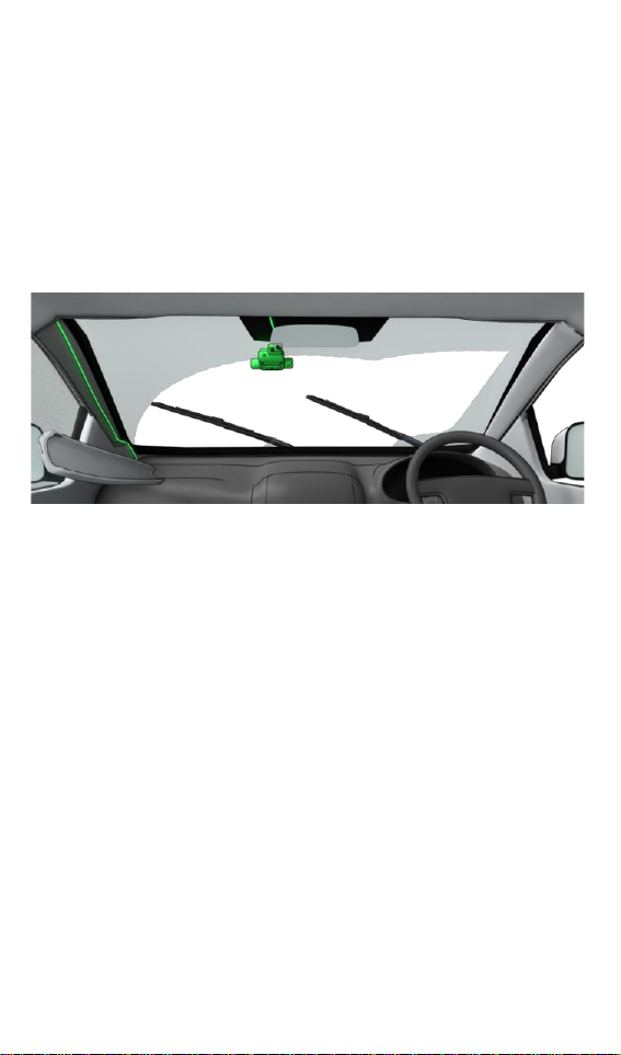
Placement
Position the dashcam inside, in the approximate middle-top of
the windshield, or if this location is already occupied, slightly
passenger-side.
The front camera should be approximately 8 inches (20 cm)
below the windshield wipers' highest sweep-point.
The unit should be mounted outside the driver’s normal sight
lines of the road ahead, highway signs, signals and all mirrors.
Mounting the Dashcam
1Clean the mounting area with the alcohol wipe provided.
2Re-wipe the area with a clean cloth to remove any residue.
3Remove the adhesive paper from the mounting plate.
4Alignment check:
5Ensure the pad orientation will hold the dashcam with the
cable facing UP.
6The road-facing camera must not be blocked by existing
ADAS units, toll tags, tints or sunshades, vehicle
certifications, other decals or objects.
7The cab-facing camera should not be blocked by mirrors,
internal shades or hanging items.
8The mounting plate is level with the horizon.
9Press the MIDDLE of the mounting plate firmly into the
windshield, working outwards, so the entire adhesive pad
touches the windshield (you can better check this
A-Pillar cover
20 cm/ 8 in [
occasionally from outside the vehicle). Push firmly for 20s.
Wait another 2 minutes for full adhesion.
10 Attach the dashcam body into the mounting plate. Leave
the protective film on the lenses until the Install Wizard
phase.
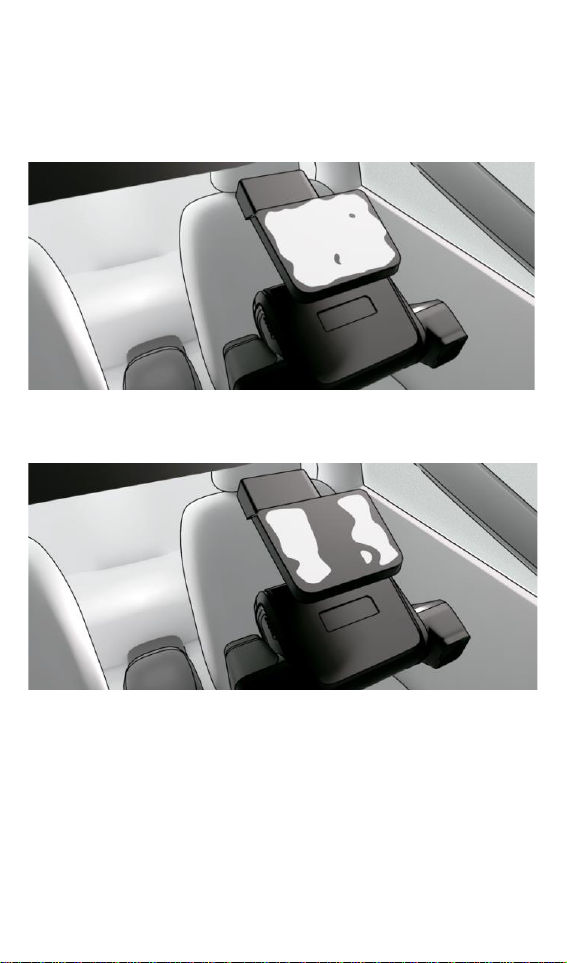
Fig.1: CORRECT Full contact with the mounting plate to the
windshield. THEN, the main body is mounted.
Fig. 2: INCORRECT Dashcam should be mounted AFTER the
mounting plate has fully stuck to the windshield.
11 Plug the main cable into the dashcam. The cable should
run:
▪Across the top of the windshield out of sight.
Fig. 1
Fig. 2
▪Down the windshield's A-pillar (out of sight, secured,
tucked into the lining trim), down the back of the
dashboard.
▪In the shortest, most convenient path to your key
connection points.
12 Find the vehicle’s junction and/or fuse box under the dash.
It’s good practice to take a picture of the vehicle’s current
configuration to use as a reference later.
13 If attaching the Remote Record button, be aware that this
can be fused on a separate circuit for vehicle power, or run
off an existing fused power circuit.
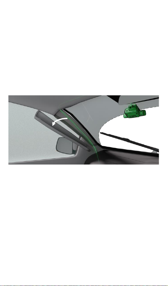
Fig. 3: A-pillar removal. A-Pillar linings use a snap-in clip,
and are removable by hand. Remove, run the cable down its
length, and replace.
Assuming a "one way fits all" approach to fleet installation is
dangerous. Differentcabs have different windshield angles, cab
configurations, wiper-blade positions and concerns around left/
right/ dual seating. It's important that you treat each cab with
individual attention to detail.
Fig. 3
A-Pillar cover

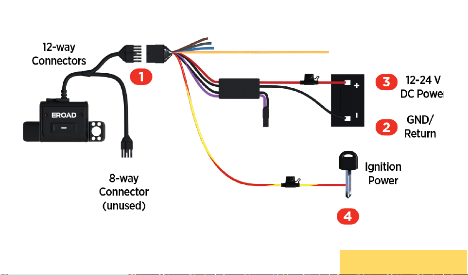
3-wire Install Using the HR003101A Loom
The following diagram shows a basic connection for the Clarity
Connected and Clarity Solo dashcams using the HR003101A 3-
wire loom along with a basic Ehubo wiring diagram. If you are
installing a Clarity Connected camera, your Ehubo is likely to
be fused and connected already.
▪RED wire fused to vehicle DC power.
▪YELLOW/RED wire fused to Ignition.
▪BLACK wire to Ground.
Note 1 Always seal wiring connections with heat shrink
and/or electrician's tape.
Do not cut cables - Coil and tie them out of the
way.
1Connect the 12-way connector from the Dashcam to the
12-way connector on the 12-way wiring loom. Secure with
electrical tape.
2Connect the BLACK wire on the 12-way wiring loom to an
appropriate grounding location.
3Connect the RED wire on the 12-way wiring loom to a
permanent power source.
Note 2 Ensure there is a constant 12‑24 V when the
key is inserted, with the engine running, and also
when the key is not inserted and the engine is off.
4Connect the RED/YELLOW-striped wire on the 12-way
wiring loom to an ignition/switched power source.
Note 3 Ensure the ignition/switched power source
supplies 12‑24 V when the key is in the ON position
and zero volts when the key is in the accessory
(ACC) and OFF positions.
3101: 3-WIRE, NO GPIOS

3-Wire Install using the HR003191A loom (Diagram)
3101: 3-WIRE, NO GPIOS
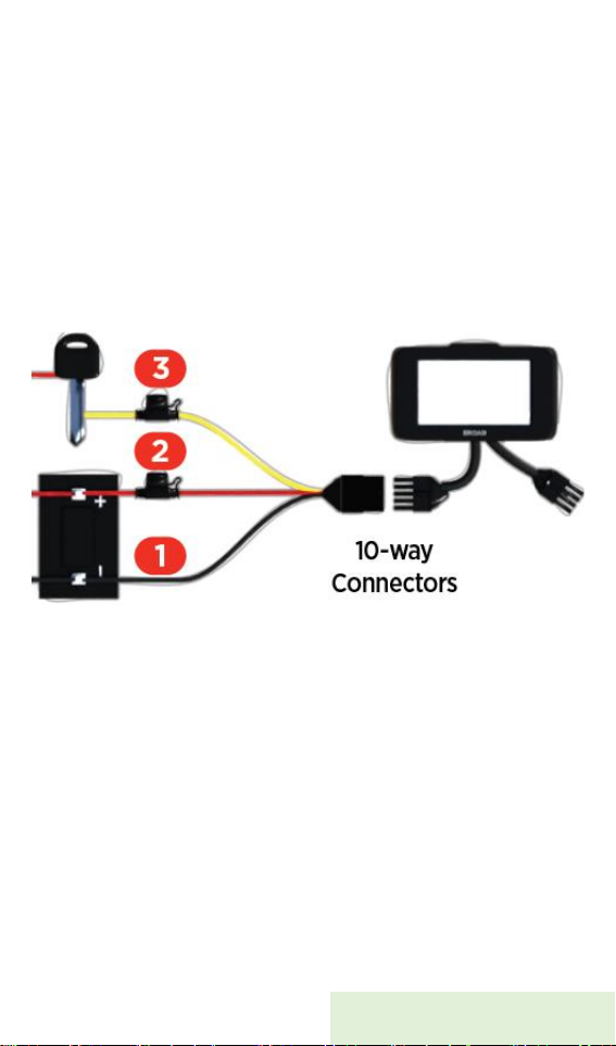
Dashcam Connected Only
Consult the dedicated Ehubo Installation Guide for full
instructions. But as a wiring check:
1Connect the BLACK wire on the 10-way wiring loom to an
appropriate grounding location.
2Connect the RED wire on the 10-way wiring loom to a
permanent power source.
3Connect the YELLOW wire on the 10-way wiring loom to an
ignition/switched power source.
4See all notes above.
3101: 3-WIRE, NO GPIOS
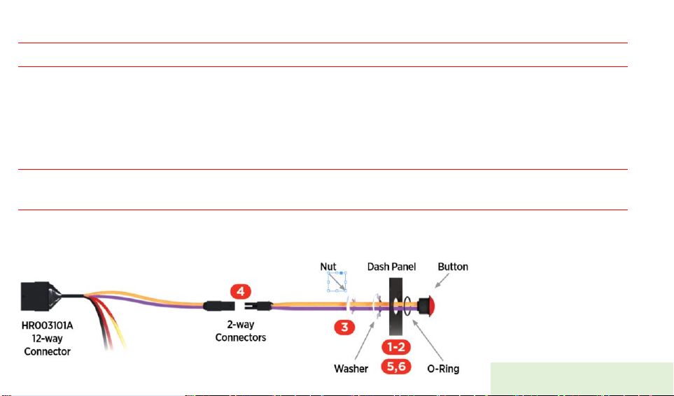
Remote record button install (HR003106)- Optional
Note 4 The 12-2 wire loom that comes with this remote button kit IS NOT USED for this install.
1Drill a 14 mm (0.55 in) diameter hole into a dashboard panel (or similar site within comfortable reach
of the driver).
2Ensure the O-ring remains near the head of the button-thread while removing the nut and washer.
3Thread the wires through the washer and nut.
4Connect the 12-way wiring loom to the Remote Record button, using the 2-way connectors provided.
Note 5 Ensure there is a constant 12‑24 V when the key is inserted, with the engine running,
and also when the key is not inserted and the engine is off.
14 Tighten the nut and washer.
15 Use cable ties to coil and tie away any excess cable.
3101: 3-WIRE, NO GPIOS

HR003101A 12-way Pin-out
1GPIO input 1 Orange
2Not Connected
3+ve power in Red
4Not Connected
5Not Connected
6Not Connected
7Ignition Yellow/Red
8Not Connected
9Not Connected
10 Ground Black
11 +ve power out Purple
12 Not Connected
2-way Connector Pin-out
1+ve power out Purple
2GPIO1, input 1 Orange
3101: 3-WIRE, NO GPIOS

3-wire Install Using the HR003100A Loom (GPIO)
The following diagram shows a basic connection for the Clarity
Connected and Clarity Solo dashcams using the HR003100A
12-wire loom along with a basic Ehubo wiring diagram. If you
are installing a Clarity Connected camera, your Ehubo is likely
to be fused and connected already.
▪Red wire fused to vehicle DC power.
▪Yellow wire fused to Ignition.
▪Black wire to Ground.
Note 6 Always seal wiring connections with heat shrink
and/or electrician's tape.
Do not cut cables - Coil and tie them out of the
way.
1Connect the 12-way connector from the Dashcam to the
12-way connector on the 12-way wiring loom. Secure with
electrical tape.
2Connect the BLACK wire on the 12-way wiring loom to an
appropriate grounding location.
3Connect the RED wire on the 12-way wiring loom to a
permanent power source.
Note 7 Ensure there is a constant 12‑24 V when the key is
inserted, with the engine running, and also when
the key is not inserted and the engine is off.
4Connect the RED/YELLOW-striped wire on the 12-way
wiring loom to an ignition/switched power source.
Note 8 Ensure the ignition/switched power source supplies
12‑24 V when the key is in the ON position and zero
volts when the key is in the accessory (ACC) and
OFF positions.
3100: 3-WIRE, GPIOS
3-wire Install Using the HR003100A Loom (GPIO, Diagram)
3100: 3-WIRE, GPIOS


Photo Verification
Part of any EROAD hardware installation is photographic
documentation of the install site. Any digital camera may be used
for 2 or 3 images per site, but images must:
▪Show the unit clearly, mounted in situ, oriented
appropriately, with its serial number whole and legible if
possible.
▪Show connections and cables secure and tidily managed.
▪Indicate the environment in which the unit is installed (its
position around the asset, under the dash, on the trailer,
wherever appropriate).
Photosare evidence of a compliantinstall. They protect EROAD’s
and the Installer’s liability, should a future 3rd party or incident
affect compliance integrity.
Specifications
Dimensions
122W x 76H x 38.5D mm
4.8W x 3.0H x 1.5D in
Weight
157.7 g
Power
9-32 V DC
Temperature
-20 to +60°C
IP Rating
IP41
Safety & Best Practice
EROAD expects installers and contractors to understand and
follow all relevant health and safety regulatory requirements.
Before installing EROAD equipment in a vehicle you must be, in

Australia, an approved EROAD installer and, in New Zealand, an
accredited EROAD installer.
The installer must wear appropriate Personal Protective
Equipment (PPE) for the install risk and customer requirements.
PPE may include safety glasses, safety shoes,work gloves, hard
hat, high visibility vest, sun cream, sun hat and coveralls. You must
understand and comply with the safety requirements of
customers or third parties.
Avoid fitting EROAD equipment in locations that could impede or
cause injury to people. This includes potential head strike zones on
the windshield or dashboard, airbag deployment locations,
seatbelts, and other safety-relevant units.
The vehicle must be parked and level, with the parking brake
engaged.
Before installation, check that other safety-relevant equipment is
working properly and report any issues to the customer.
Before installers are permitted to work under or around
suspended equipment –held aloft with slings, hoists, or jacks –
ensure the equipment is secured to prevent collapse or falls.
Avoid running cables close to heat sources, sharp edges, high
voltage lines, obstacles or safety-relevant units.
After installation, check that all other safety-relevant equipment
continues to work properly.
While EROAD hardware is comprehensively tested against
corrosion and ingress, they are not invulnerable to water, fire or
impact damage. Do not subject EROAD units to extreme heat,
high-pressure water force or other intense physical forces.
Protect this unit and other EROAD units from extreme
temperatures. Operating temperatures for the equipment related
to this guide are found in the Specifications section.
Legal

This installation guide sets out the minimum installation
requirements that Installers must meet when installing EROAD
equipment.
It is the customer’s responsibility to ensure their chosen Installer
complies with the instructions and specifications in this document.
When performing the installation, Installers must comply with all
applicable laws, rules, and standards.
The customer is responsible for their own compliance with
applicable laws, rules, and standards, including privacy laws. Note
in some jurisdictions, the customer and the driver(s) are required
to advise all vehicle occupants that the vehicle is equipped with
audio and video recording equipment.
Use of the EROAD CoreHub Xtreme is subject to the terms and
conditions outlined on EROAD’s website.
EROAD disclaims all liability for any installation of EROAD
equipment in a way that may cause accidents, damage, or violate
the law.
Table of contents
Other EROAD Dashcam manuals


