ERR Cruise Commander Lite User manual

Cruise CommanderTM Lite
Instruction Manual
The Electric Railroad Co.
939 Wood Duck Avenue
Santa Clara, Ca. 95051
Revised: November 2006

Cruise Commander Lite
TMCC Compatible DC Cruise Command Upgrade Board
Overview
The patented Cruise Commander Lite with SMS* Technology tm is a breakthrough in
cruise control technology for 3-rail. The Cruise Commander product line uses motor
commutation and back-EMF to monitor the speed of the motor(s) attached instead of
an external tachometer sensor. This method of motor control is easier to install than
attaching an optical tachometer and timing tapes, and does not require a flywheels on
the motor. With the Cruise Commander product installed, the performance of the
locomotive will be greatly enhanced.
The Cruise Commander Lite has a lash-up feature, referred to as “nudge mode”. The
mode allows a person to match the locomotives in a lash-up. Once the speeds are
matched, they dynamically adjust with throttle position. The “nudge” settings are
saved for future operating sessions, however may be easily reset.
The Cruise Commander product line is capable of operating in 32 - speed step mode
for speed profile compatibility with most existing engines. The default setting for the
Cruise Commander Lite is 100 speed steps. The Cruise Commander product line
uses the sound system to indicate configuration changes by blowing the whistle/horn
for acknowledgement.
SMS* - Speed Management System
Enhanced Features
Simple Tach-Less installation and operation
Operates in command and conventional modes
Single or Dual DC motor capability (4 Amps)
CAB-1tm selectable 32 or 100(default) speed steps
Coil Couplers, Smoke, Strobe / Cab / Marker Lamp supported
Horn pulse output to control post-war and modern-era horns
Uses Lionel R2LC to be fully compliant with TMCC standards.
Full Functions
Available in an 4 Amp DC motor version, additionally connecting Front and Rear
Coupler, Front and Rear headlights, and Smoke or Strobe light outputs.
Small Footprint
2.4” L x 1.63” W x 0.8” H footprint
Included with Board
2
Antenna, hook-up wires, P/R switch, wire ties, mounting hardware

Cruise Commander Lite Connector Pin Designations
Installation Overview
Tin the wires that go into the mini screw terminal strip to prevent stray stands of wire. Be
sure that the screws in the mini terminals are turned counter-clockwise to open, before
wiring. Do not over tighten terminal screws when attaching the wires.
The PROGRAM / RUN switch should be positioned in a convenient location in the chassis.
If the engine currently has a reverse lockout switch it can be used in place of the included
switch. The switch is used to configure the receiver using the Program mode or Run mode.
The switch is in the RUN position when it is open (with the slide lever over the unused
terminals) and in Program when in the closed position.
Locate a suitable mounting location for the Cruise Commander Lite. Be certain the shell
will fit without obstruction. If you plan to add RailSounds, the Sound Commander, or keep
the horn present in the low cost engines, be sure there is room for everything before
mounting. When possible, use the original “E” unit mounting bracket.
3

Installation, Preparation Phase
Please take time to plan out your installation. Before you begin, examine the wiring already
present in the locomotive. Shown below is a Lionel GP-20 with truck mounted can motors.
The electronic “E” unit is depicted on the right below. The small circuit board on the left is
the Sound unit.
GP-20 before installation begins
First the original electronic “E” unit needs to be removed. Cut the wires as close to the
circuit board as possible. It is wise to make a drawing of the original connections for later
reference. The Cruise Commander Lite is slightly wider than the original circuit board;
therefore it is necessary to remove the top mounting clips on the plastic mount.
Remove (cut off) these clips
“E” unit removed
4

Installation, Mounting the Cruise Commander Lite
• Using the double stick tape provided in the kit place a square piece on the back of the
Cruise Commander Lite board as shown below.
Attach the double stick tape as shown
• Test fit, remove tape backing, and secure the Commander Lite as shown below.
Cruise Commander Lite board mounted
5

Installation, Wiring Phase
• Connections to the power are made first. Be sure to get the AC HOT and AC COMMON
identified correctly. In this locomotive, the Brown and Gray were the power pickup
wires, with the gray being the HOT, or 3rd rail. Use an ohmmeter to confirm your
locomotive’s wiring.
• The Blue/White wires on this loco are from the original direction lockout switch. This
can be used for the program/run Switch. Connect one of the wires from the direction
switch to the wire nut that is the AC COMMON connection.
• Locate a 2-pin connector with black and white wires, and plug this into the “Antenna &
Prog/Run” socket. Splice the other wire from the direction switch into the connector pin
marked “Prog/Run” in the pin designations. Leave the wire that corresponds to the
“Antenna” connection free at this time.
• Connect the wires from the motor(s) to the ”Motor” connections on the board. Do not
install any caps across the motor brushes. Do not try to figure out the correct motor
wiring polarity, we must test this now to figure out the correct polarity:
• In this example, the red and black wires are the motor connections. Locate a 2-pin
connector with white and black wires. Plus this into the “Motor” connector on the
Cruise Lite board. Connect these to the motor wires by twisting, and place a piece
of tape over the connections.
• Install the R2LC. Use caution not to miss by one pin pair to either side, as this
will certainly damage the components on both cards
• Check the Direction switch is “ON” (Run), and secure stray wires to prevent
shorting out to the track, and then test run the loco.
• When powered up, the loco default direction will be forward. If the loco goes
forward, splice the wires as connected. If the loco goes reverse, swap the wires
and splice.
• Remove the R2LC and set it aside.
• Locate the 3-pin connector with the Red, Black and White, wires. Plug this into the 3-pin
“Lamp” connector. Wire the lights as appropriate.
• If there is a Strobe Lamp, or a Smoke unit, this connection is made to the “Smoke” plug
using a 2-pin connector.
• If the loco is to have coil couplers, install them now, and plug them into the “Front and
Rear Coupler” connections.
6

Installation, Optional Sound Control
Disclaimer: This phase of the installation involves modification of the Sound Board.
Done incorrectly, the board may be irreparably damaged. Proceed at your own risk!
The Electric Railroad Company does not warranty this modification, and any damage
done by making this modification is the sole responsibility of the user.
• Included in the kit is a 4-pin connector with one wire. This wire is a sound trigger signal
that works by injecting a DC offset into the convention sound systems. When this
connection is made, the injected signal makes the sound system think it has a DC offset,
thus it activates.
• This Picture shows the connection to be made on the conventional sound system in this
are also some sound system connection examples in the AC/DC Commander manual
available on-line.
7

Installation, Finishing touches
• The picture below shows the finished installation. A wire nut (not supplied) was used to
connect a shortened “Antenna” connection to a wire hot melt glued in the shell roof. This
allows the Shell to be removed easily, since the lighting can be removed by unplugging
the 3-pin lamp connector.
R2LC Installation
• Double check all wiring, then install the R2LC receiver board onto the Cruise
Commander Lite board. Use caution not to miss by one pin pair to either side, as this
will certainly damage the components on both cards.
8

Operation
Speed Step Selection
The default speed step selection is 100 as shipped. The 100 speed steps are linear. The 100
speed steps start at a lower threshold, thus the motor is operating at a lower initial voltage
with fine adjustment as the throttle is advanced. The momentum and stall features are not
applicable, and do not operate.
To switch Speed Steps do the following:
Activate 32 Speed Steps: AUX1 + 0 + AUX1 + 0 + BRAKE
Activate 100 Speed Steps: AUX1 + 0 + AUX1 + 0 + BOOST
Note: The speed step selection is stored until changed, and survives power cycling.
Motor Type Selection
The Cruise Commander Lite requires you to set the motor type. Motors are classified as
small or large. Selecting the wrong motor size won’t hurt anything, but operation is best
when matched. The default motor type is “small motor” for the Cruise Commander Lite.
To switch Motor Type do the following:
Activate Small Motor: AUX1 + 0 + AUX1 + 1
Activate Large Motor: AUX1 + 0 + AUX1 + 2
Note: The motor type selection is stored until changed, and survives power cycling.
Cruise On/OFF Selection
The Cruise feature may be turned on or off. This setting is stored and affects command and
conventional mode operation.
To turn the Cruise OFF or ON, do the following:
Cruise Off: AUX1 + 0 + AUX1 + BRAKE + 7 + BRAKE
Cruise On: AUX1 + 0 + AUX1 + BRAKE + 9 + BRAKE
Note: The cruise off/on selection is stored until changed, and survives power cycling.
9

Operation Continued
“Nudge Mode” Operation
The Cruise Commander Lite has a bit of “play” to allow locos to operate in a lash-up. At
times the “play” is not optimal, so it is possible to match locos a bit closer with the “Nudge”
mode feature. Remember to lash-up only very similar locos, and it is a requirement the gear
ratios match.
First, simply try the locos together in a lash-up at slow speeds. If they buck each other, use
the Cruise Commander Lite “nudge” mode to try to match the locos a bit closer. Nudge
mode basically increases the slower loco to match the speed profile of the faster loco.
Although similar to a “stall” setting, the nudge mode is a bit more complex as it calculates
the speed profile dynamically to hold the locos in sync throughout the throttle range.
First create a “TRain” with the Cab-1. Once the locos are operating in TRain mode do the
following:
• Test run the locos (not coupled) to find the slower loco
• Place the slower loco behind the faster one
• Get them moving as a train, around 10 speed steps on the throttle
• Select the slower loco ENG ID
• Press AUX2 4 times, with a 1 second pause between each press
• The lights should blink off twice, confirming the loco to be “Nudged”
• Use the Boost and Brake keys to adjust the slower loco to match the faster one
• Press “HORN” to lock the setting in the slower loco.
• Couple the locos together and run as TRain.
To operate the “Nudge” mode on an ENG ID, do the following:
Activate: AUX2 + AUX2 + AUX2 + AUX2
Nudge: BOOST to speed up, Brake to slow down
Save: Horn
To clear the nudge settings, select the speed step (32 or 100) on the “nudged” loco.
Note: the “nudge” selection is stored until changed, and survives power cycling.
10

Setting the R2LC ID and feature code
Setting the engine ID Number:
The R2LC Receiver comes with its engine ID set to ENG ‘1’. To change the engine ID,
follow this procedure.
1. Make sure the Command Base is connected to the track
2. Set the engine PROGRAM / RUN switch to “PROGRAM”
3. Place the engine on the track and apply power
4. On the CAB-1, press [ENG] then the number (1 - 99) for the engine desired
5. Press [SET] (the engine ID is saved until you need to change it again)
6. Press [AUX1] [n], where n = the engine feature code (this must be done!)
7. Remove power from the track and place the switch back into the ‘RUN’ Position
Feature Code information:
The R2LC receiver module can be programmed to operate different features for different
engines. Use only codes “4” through “8” for proper operation.
Code Engine Type Feature Terminal
0Steam w/ Signal sounds Smoke Unit
1Diesel w/ Signal sounds Strobe Light
2Diesel w/ Signal sounds Cab / Marker Light
4Steam w/ Rail sounds Smoke Unit
5Diesel w/ Rail sounds Strobe Light
6Diesel w/ Rail sounds Cab / Marker Light
8Diesel w/ Rail sounds Smoke Unit
Why is it necessary to set the Feature Code?
The Cruise Commander Lite uses the serial data from the R2LC receiver to detect the
throttle settings. This serial data signal is dependent on the feature code. If this is not
properly set, the loco will not respond to throttle commands and may even enter into
conventional mode and rocket down the rails! Additionally, features like the smoke unit will
not operate until the feature code is set. It is always a good idea to know your loco feature
codes for proper operation of smoke/strobe/cab/marker lighting effects. This is true of your
entire TMCC loco stable.
When running in Conventional mode:
Cycling of engine direction can be overridden by placing the programming switch in the
’PROGRAM’ position. This will lock the engine direction to the last operating direction.
You must replace the switch back to the ‘RUN’ position if you wish to run the engine in
Command mode.
11

12
Limited Warranty
The Electric Railroad Company warrants to the original consumer purchaser that this product will be free of
defects in materials and workmanship for a period of 90 days from the date of original purchase. This
warranty does not cover service, repair, or replacement to correct any damage caused by improper
installation, improper connection, external electrical fault, accident, disaster, misuse, abuse, or modifications
to the product. All other express or implied warranties, including the implied warranty of merchantability
and fitness for a particular purpose, are hereby disclaimed. If this product is not in good working order as
warranted, the sole and exclusive remedy shall be repair or replacement. In no event shall The Electric
Railroad Company, or any dealer, distributor, or authorized installation and/or repair service provider be
liable for any damages in excess of the purchase price of the product. This limitation applies to damages of
any kind, including but not limited to, direct or indirect damages, lost profits, lost savings or other special,
incidental, exemplary or consequential damages whether for breach of contract, tort or otherwise, or
whether arising out of the use of or inability to use the product, even if The Electric Railroad Company, or
any dealer, distributor, or service provider has been advised of the possibility of such damages or any claim
by any other party. Some states do not allow the exclusion or limitation of incidental or consequential
damages so the above limitation or exclusion may not apply to you. During this warranty period, the
product will either be repaired or replaced (at our option) without charge to the purchaser, when returned
either to the dealer with proof of the date of purchase or directly to The Electric Railroad Company when
returned prepaid and insured with proof of date of purchase. Some states do not allow limitations on how
long an implied warranty lasts, so such limitations may not apply to you. This warranty gives you specific
legal rights, and you may also have other rights, which vary from state to state.
Repairs
Each and every product is thoroughly tested before it is shipped. The likelihood that it is not working when
it reaches you is very small. However, if after troubleshooting it yourself you cannot get it to work properly,
you should contact us to help determine the problem.
Should your product ever need repair, you should return it postpaid directly to The Electric Railroad
Company. If the product is within the warranty period, it will be repaired or replaced and returned to you
free of charge. Units out of warranty will be repaired or replaced for a service charge of $50.00 at our
option.
Disclaimer
Improper installation or configuration of the Cruise Commander Lite Board can cause
overheating and fires! Since it is not possible to understand every installation, it is the
consumer’s responsibility to verify proper operation of the upgrade to prevent malfunction.
If you are unsure of install, please contact us first before taking any risks!
All manual contents are Copyright ©2006, The Electric Railroad Company.
TMCC, CAB-1, R2LC, SignalSounds, and RailSounds are registered trademarks of Lionel, LLC.
Table of contents
Popular Control Unit manuals by other brands

BRÖTJE
BRÖTJE VGU 86 S installation instructions
Allen-Bradley
Allen-Bradley CENTERLINE 2100 installation instructions
Comunello Automation
Comunello Automation MOWIN instruction manual
Crane
Crane CRYOFLO T-Globe Installation, operation and maintenance manual
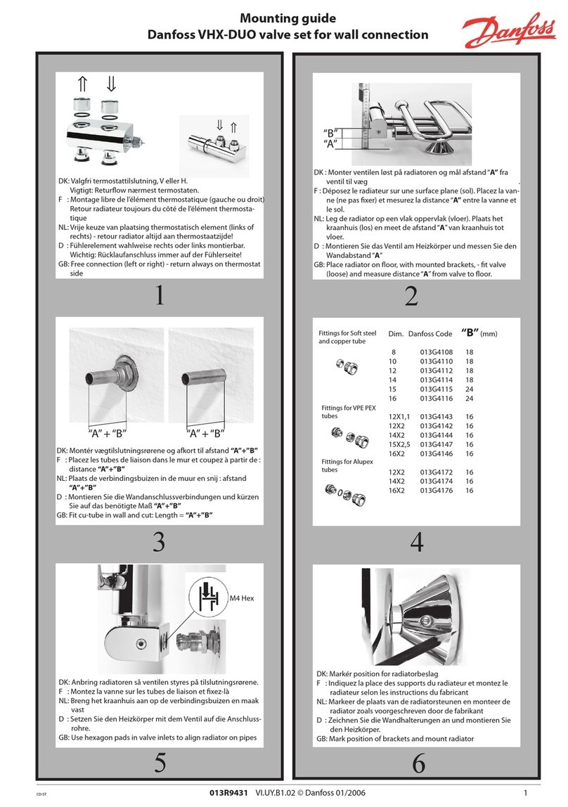
Danfoss
Danfoss VHX-DUO Mounting guide

Banner
Banner DUO-TOUCH SG manual


