manuals.online logo
Brands
  1. Home
  2. •
  3. Brands
  4. •
  5. Omron
  6. •
  7. Control Unit
  8. •
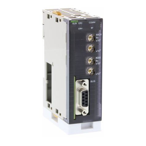
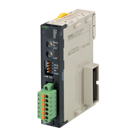
  9. Omron CQM1-SRM21-V1 User manual

Omron CQM1-SRM21-V1 User manual

Other Omron Control Unit manuals
Omron C500-SNT31-V4 User manual

Omron

Omron C500-SNT31-V4 User manual

Omron 3G3FV-PDI16H2 User manual

Omron

Omron 3G3FV-PDI16H2 User manual

Omron NX Series User manual

Omron

Omron NX Series User manual

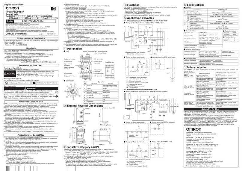
Omron F3SP-U5P User manual

Omron

Omron F3SP-U5P User manual

Omron C200HW-SRM21-V1 - 08-2007 User manual

Omron

Omron C200HW-SRM21-V1 - 08-2007 User manual

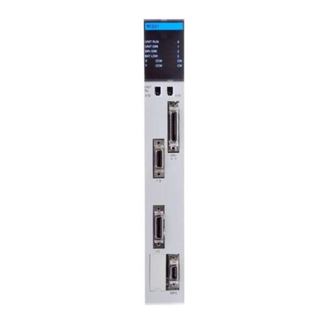
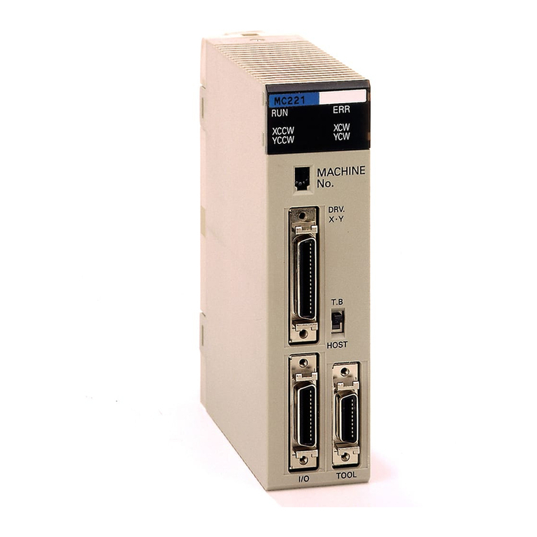
Omron CV500-MC221 User manual

Omron

Omron CV500-MC221 User manual

Omron 3G3AX-DI User manual

Omron

Omron 3G3AX-DI User manual

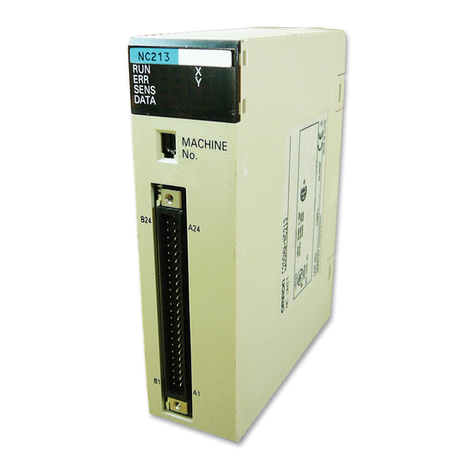
Omron SYSMAC C200H-NC111 User manual

Omron

Omron SYSMAC C200H-NC111 User manual

Omron 3G3FV-PPG Series User manual

Omron

Omron 3G3FV-PPG Series User manual

Omron CS1W-NC113 - REV 02-2008 User manual
Omron

Omron CS1W-NC113 - REV 02-2008 User manual

Omron CJ Series User manual

Omron

Omron CJ Series User manual

Omron F3SN-A - User manual

Omron

Omron F3SN-A - User manual

Omron C200H-MC221 - User manual

Omron

Omron C200H-MC221 - User manual

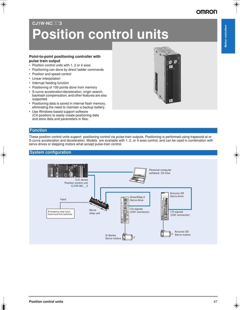
Omron CJ1W-NC271 - 12-2009 User manual

Omron

Omron CJ1W-NC271 - 12-2009 User manual

Omron SYSMAC LINK C1000H-SLK21-V1 User guide

Omron

Omron SYSMAC LINK C1000H-SLK21-V1 User guide

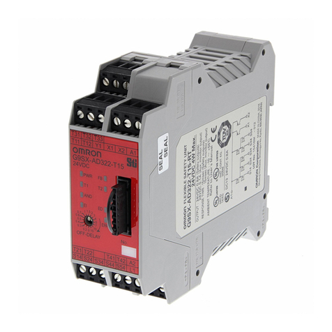
Omron G9SX-AD322-T15-RT User manual

Omron

Omron G9SX-AD322-T15-RT User manual
Omron NX Series User manual

Omron

Omron NX Series User manual

Omron G9SX Series User manual

Omron

Omron G9SX Series User manual

Omron CS1W-CLK12-V1 User manual

Omron

Omron CS1W-CLK12-V1 User manual
Omron SYSMAC C500-NC113 User manual

Omron

Omron SYSMAC C500-NC113 User manual

Omron CJ1W-NC271 Quick guide

Omron

Omron CJ1W-NC271 Quick guide

Omron SRM1-C01-V2 User manual

Omron

Omron SRM1-C01-V2 User manual

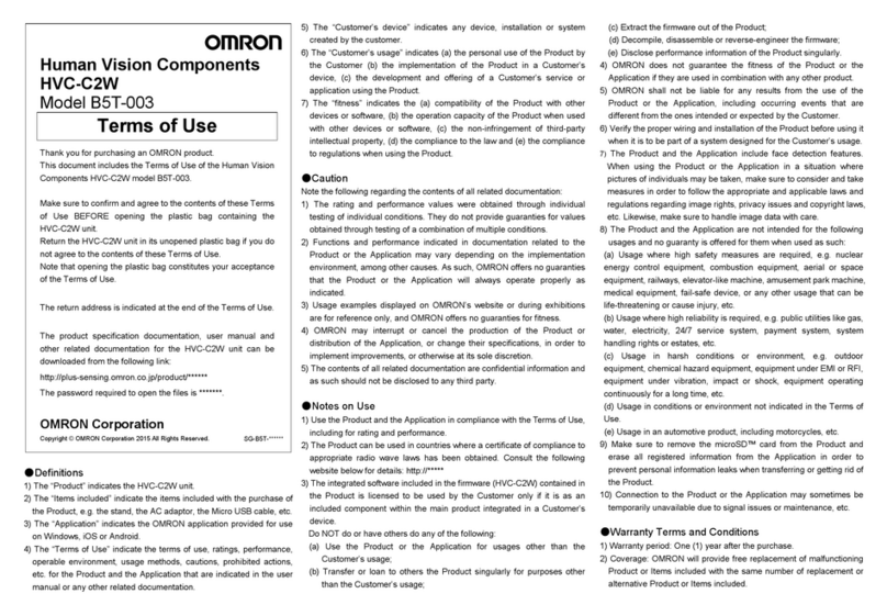
Omron B5T-003 User manual

Omron

Omron B5T-003 User manual
Omron SYSMAC SRM1-V2 User manual

Omron

Omron SYSMAC SRM1-V2 User manual

Popular Control Unit manuals by other brands

Seitz 14A80 user manual

Seitz

Seitz 14A80 user manual

Wilo RS485 Installation and operating instructions

Wilo

Wilo RS485 Installation and operating instructions

Becker CentralControl CC41 Commissioning Instruction

Becker

Becker CentralControl CC41 Commissioning Instruction

SICK CDB650 operating instructions

SICK

SICK CDB650 operating instructions

Panduit NetKey NKP5E88M Series installation instructions

Panduit

Panduit NetKey NKP5E88M Series installation instructions

MX Options Concentric Petite Fitting instructions

MX

MX Options Concentric Petite Fitting instructions

Clean Water Systems Fleck 2510 Installation & start?up guide

Clean Water Systems

Clean Water Systems Fleck 2510 Installation & start?up guide

Fairchild FSB44104A user guide

Fairchild

Fairchild FSB44104A user guide

LEGRAND Wattstopper LMIN-104 installation instructions

LEGRAND

LEGRAND Wattstopper LMIN-104 installation instructions

PMK ATT10BNCS instruction manual

PMK

PMK ATT10BNCS instruction manual

Tektronix TDS3FFT user manual

Tektronix

Tektronix TDS3FFT user manual

Woodward easYgen Technical manual

Woodward

Woodward easYgen Technical manual

Balluff BNI EIP-502-105-R015 user guide

Balluff

Balluff BNI EIP-502-105-R015 user guide

NXP Semiconductors TWR-LS1021A Getting started

NXP Semiconductors

NXP Semiconductors TWR-LS1021A Getting started

Advantech PCM-3117 Startup manual

Advantech

Advantech PCM-3117 Startup manual

Danfoss MCO 101 manual

Danfoss

Danfoss MCO 101 manual

Moons' Lin Engineering R701P user manual

Moons'

Moons' Lin Engineering R701P user manual

Aventics RV1 operating instructions

Aventics

Aventics RV1 operating instructions

manuals.online logo
manuals.online logoBrands
  • About & Mission
  • Contact us
  • Privacy Policy
  • Terms and Conditions

Copyright 2025 Manuals.Online. All Rights Reserved.

9
CompoBus/S Master Module CQM1-SRM21-V1
Wire-saving CompoBus/S Remote
I/O for Compact CQM1 Controllers
1128 remote I/O points maximum; also
canbesetfor32or64I/Opoints
1Master connects to a maximum of 16 or
32 slaves
1Fast communications of 0.5 ms max. at
standard distance of 100 m (750 kbps)
1Extended distance communications to
500 m (93.75 kbps)
1Supports analog input and output slave
blocks
1Flat, 4-conductor cable or Belden #9409
twisted pair cable connects master to
terminal blocks
èò
Ordering Information
3COMPOBUS/S MASTER MODULE
Compatible Omron controller Maximum number of I/O points Part number
CQM1-Series PLCs 128 points (64 inputs/64 outputs) CQM1-SRM21-V1
3ACCESSORIES
Item Specification Part number
Communications cable Flat cable, 100 m length, 4 conductor (0.75 mm2each) SCA1-4F10
Branch connector Sold in packs of 10 SCN1-TH4
Extension connector Sold in packs of 10 SCN1-TH4E
Connector terminator Sold in packs of 10 SCN1-TH4T
Terminal block terminator Sold in packs of 10 SRS1-T
CQM1-SRM21-V1 CQM1-SRM21-V1
2
Specifications
3COMMUNICATIONS SPECIFICATIONS
Communications method CompoBus/S protocol
Coding method Manchester coding method
Connection method Multi-drop method and T-branch method (See Note)
Communications baud rate 750,000 bps, 93,750 bps (selected by DIP switch)
Communications
c
y
c
l
e
t
i
m
e
High-speed
c
o
m
m
n
i
c
a
t
i
o
n
s
0.5 ms with 8 Slaves for inputs and 8 Slaves for outputs
cyc
l
et
i
me commun
i
cat
i
ons
mode 0.8 ms with 16 Slaves for inputs and 16 Slaves for outputs
Long-distance
c
o
m
m
n
i
c
a
t
i
o
n
s
4.0 ms with 8 Slaves for inputs and 8 Slaves for outputs
commun
i
cat
i
ons
mode 6.0 ms with 16 Slaves for inputs and 16 Slaves for outputs
Communications cable 2-conductor Belden #9409 or VCTF cable (0.75 x 20)
Dedicated flat cable
Communications
distance High-speed
communications
mode
Belden #9409 or VCTF cable:
Main line length: 100 m(328.1 ft) max.
Branch line length: 3 m (9.84 ft) max.
Total branch line length: 50 m (164.0 ft) max.
Flat cable:
Main line length: 30 m (98.4 ft) max.
Branch line length: 3 m (9.84 ft) max.
Total branch line length: 30 m 98.4 ft) max.
(When flat cable is used to connect fewer than 16 Slaves, the main line can be up to
100 m (328.1 ft) long and the total branch line length can be up to 50 m (164.0 ft.)
Long-distance
communications
mode
Belden #9409 or VCTF cable:
Main line length: 500 m (1640.5 ft) max.
Branch line length: 6 m (19.69 ft) max.
Total branch line length: 120 m (393.7 ft) max.
Max. number of connecting nodes 32
Error control checks Manchester code check, frame length check, and parity check
Note: A terminator must be connected to the point in the system farthest from the Master.
3MODULE SPECIFICATIONS
Current consumption 180 mA max. at 5 VDC
Number of I/O points 128 points (64 inputs/64 outputs), 64 points (32 inputs/32 outputs),
32 points (16 inputs/16 outputs) (switchable)
Number of occupied words 128 points: 4 input words/4 output words
64 points: 2 input words/2 output words
32 points: 1 input word/1 output word
PLC 128 points: CQM1-CPU41-EV1/CPU42-EV1/CPU43-EV1/CPU44-EV1
64 points: CQM1-CPU11-E/CPU21-E/CPU41-EV1/CPU42-EV1/CPU43-EV1/CPU44-EV1
32 points: CQM1-CPU11-E/CPU21-E/CPU41-EV1/CPU42-EV1/CPU43-EV1/CPU44-EV1
Number of points per node number 4/8 points (switchable)
Max. number of slaves per master 32 (4 points per node number)
Status data Alarm terminal output
Weight 200 g max.
Approved standards UL 508 (E95399), CSA C22.2 No. 142 (LR51460)
CQM1-SRM21-V1 CQM1-SRM21-V1
3
3ALARM OUTPUT SPECIFICATIONS
Maximum switching capacity 2 A at 24 VDC
Minimum switching capacity 10 mA at 5 VDC
Relay G6D-1A
Minimum ON time 100 ms
Circuit configuration
2 A at 24 VDC max.
Internal
circuit
CQM1--SRM21--V1
3RATINGS
The ratings of the Unit are the same as those for the CQM1.
Nomenclature
Indicators
Indicates the operating status of the Master Module and
the status of communications with the Slaves.
DIP Switch
These pins have the following functions:
Pins 1 and 2: PLC word allocation setting
Pin 3: Number of points setting
Pin 4: Baud rate setting
Pins 5 to 6: Reserved (always OFF)
Alarm Output Terminals
These terminals are shorted when an error occurs.
Connect to a warning device.
Communications Terminals
Connect the Slaves’ transmission cable to these
terminals.
Terminal block screws
These screws attach the terminal
block. The terminal block can be
removed when these screws are
loosened.
CQM1-SRM21-V1 CQM1-SRM21-V1
Dimensions
Unit: mm (inch)
3CQM1-SRM21-V1
Note: Refer to the
CQM1 Operation Manual
for details on the dimensions
when the Master Module is installed as part of the PLC’s integrated
backplane.
110
(4.33)
32 (1.26) 107 (4.21)
Precautions
Refer to the
CompoBus/S Operation Manual (W266)
before using the module.
Cat. No. GC RIO-1 04/00 Specifications subject to change without notice. Printed in U.S.A.
OMRON ELECTRONICS, INC.
OneEastCommerceDrive
Schaumburg, IL 60173
NOTE: DIMENSIONS SHOWN ARE IN MILLIMETERS. To convert millimeters to inches divide by 25.4.
1-800-55-OMRON
OMRON CANADA, INC.
885 Milner Avenue
Scarborough, Ontario M1B 5V
8
416-286-6465
9