Erskine Attachments HP35 User manual

Commercial High Flow
Hydraulic Power Unit
HP35
For
Tractors with 80-150 PTO HP
540 RPM input speed
Operator’s Manual
Set-Up Assembly
Maintenance
Parts Information
Read this Manual Before Use

2
SAFETY
3-4
SERIAL NUMBER/DECAL LOCATION
5-6
SET-UP ASSEMBLY
7
MOUNTING INSTRUCTIONS
8-9
OPERATING INSTRUCTIONS
10-11
ROUTINE MAINTENANCE
12
BOLT TORQUE INFORMATION
13
PARTS INFORMATION
14
GENERAL SPECIFICATIONS
15
OIL VISCOSITY CHART
16
NOTES
17-18
WARRANTY
19
NOTE: Erskine Attachments LLC reserves the right to make
improvements in design or changes in specifications at any time
without notice and without incurring any obligations to install them on
units previously sold.
TABLE OF CONTENTS
REFERENCE INFORMATION
Write the correct information for your attachment in the spaces below. Always refer to this
serial number when calling for service or parts.
Serial Number…………..
YOUR ATTACHMENTS DEALER
ADDRESS:
PHONE:
CONTACT:

3
The user is responsible for inspecting the machine
daily, and for having parts repaired or replaced when
continued use of the machine would cause damage,
excessive wear to other parts or make the machine
unsafe for continued operation.
If an operating procedure, tool device, maintenance
or work method not specifically recommended is
used; you must satisfy yourself that it is safe for you
and others. You must also ensure that the
attachment will not be damaged or made unsafe by
the procedures you choose.
Erskine Attachments LLC cannot anticipate every
possible circumstance that might involve potential
hazard. The safety messages found in this manual
and on the machine are therefore not all inclusive.
The signal words CAUTION, WARNING, or
DANGER are used to indicate hazards.
Indicates a potentially
hazardous situation which, if not avoided,
may result in minor or moderate injury.
Indicates a potentially
hazardous situation which, if not avoided,
could result in death or serious injury.
Indicates a potentially
hazardous situation which, if not avoided,
will result in death or serious injury.
The word IMPORTANT is used in the text when
immediate damage will occur due to improper
technique or operation.
The word NOTE is used to convey information that
is out of context with the manual text; special
information such as specifications, techniques,
reference information, and other information of a
supplementary nature.
SAFETY
DO NOT use or perform maintenance on this machine until this manual has been
read and understood. In addition, read the Operation and Maintenance
Manual(s) pertaining to the attachment and the attachment carrier (“Tractor”).

4
Improper operation can cause serious
injury or death.
Pre-operation
•This attachment is designed to generate continuous
hydraulic flow to run attachmentsmounted on thefront
of a tractor only. NEVER use this machine for any
other purpose.
•Read the operators manual for the “Tractor”. NEVER
allow untrained people to operate.
•Operating instructions must be given to everyone
before operating this attachment and at least once a
year thereafter in accordance with OSHA regulations.
•NEVER exceed the maximum recommended input
power or speed specifications for the attachment.
Over-powering or over-speeding the attachment may
cause personal injury and/or machine damage.
•NEVER use machine with an attachment that is
heavier than the rated lift capacity of the tractor.
Instability can lead to serious injury or death.
•Keep all shields, guards, and covers in place.
•Do not modify equipment or add attachments that are
not approved by Erskine Attachments LLC.
•Use adequate safety warning lights and devices as
required by local regulations. Obey all local laws and
regulations regarding machine operation on public
property.
•Only use attachment with a tractor equipped with a
Roll Over Protection System (ROPS) and seatbelt.
Operation
•Avoid loose fitting clothing. Clothing caught in moving
parts may lead to serious injury or death.
•To protect the operator from hearing loss, ear
protection is required unless the tractor is equipped
with a noise reduction cab that meets OSHA 1910.95
standard.
•Hydraulic connections may be hot after use. Use
gloves if connecting or disconnecting after use.
SAFETY
Operation
•Check and be sure all operating controls are in
neutral before starting the engine.
•Keep people away from tractor andattachment when
in use.
•NEVER operate near embankments or terrain that is
so steep that rollover could occur.
•Always stay in the operator position with seatbelt
fastened when using the attachment.
•Before leaving the operators position, disengage
PTO drive, stop engine, set park brake, and wait for
all motion to stop.
•NEVER place hands near attachment while
engine is running.
Avoid High Pressure Fluids Hazard
•Escaping fluid under pressure can
penetrate the skin causing serious injury.
•Avoid the hazard by relieving the
pressure before disconnecting hydraulic
lines.
•Use a piece of paper or cardboard, NOT BODY
PARTS, to check for suspected leaks. Wear
protective gloves and safety glasses or goggles
when servicing or performing maintenance on
hydraulic systems.
•If an accident occurs, see a doctor immediately. Any
fluid injected into the skin must be surgically
removed within a few hours or gangrene may result.
Maintenance
•NEVER make adjustments, lubricate, clean, or
perform any service on the machine while it is in
operation.
•Make sure the attachment is serviced on a daily
basis. Improper maintenance can cause serious
injury or death in addition to damage to the
attachment and/or your equipment.

5
SERIAL NUMBER AND SAFETY DECAL LOCATIONS
Serial Number Location:
It is important to refer to the serial number of your attachment when making repairs or ordering parts. Early
or later models (identification made by serial number) may use different parts, or it may be necessary to use
different procedures in doing a specific operation.
A
C
B
SERIAL PLATE
E
D

6
Part number: 317694
Location: Back side of tank
Quantity: 2
Part number: 300245
Location: Left and right side of tank
Quantity: 2
SERIAL NUMBER AND SAFETY DECAL LOCATIONS________
Part Number: 300447
Location: Both sides of tank
Quantity: 2
Part Number: 423956
Location: Left side of tank
Quantity: 1
Safety Decal Locations:
The locations of the safety decals are shown. If these
decals are missing, damaged, or painted over they
must be replaced. Call Erskine Attachments LLC
(218-435-4045) for replacement decals.
Large Brand Decal
Location: Rear of frame
Quantity: 1
A
B
C
Part number: 200001
Location: Left side of tank
Quantity: 1
E
D

7
SET-UP ASSEMBLY
After uncrating the unit, use the following instructions to assemble to PTO power unit.
1. Slide the driveline onto the gearbox shaft of the
pump unit.
IMPORTANT: Make sure the driveline is locked
into the groove of the gearbox input shaft by
pulling on the driveline.
2. Rest the driveline in the J-shaped hanger.
3. Place the lower 3-point pins in the appropriate
location to match the hitch category of your
tractor. The inner set of ears are CAT II and the
outer set are CAT III.
4. The top pin has two positions. The pin should be
mounted in the top hole when connecting the
tractor top link directly to the tank. The pin should
be mounted in the bottom hole when connecting
to the tank using a quick-hitch system.
NOTE: Additional bushings may be needed on
the upper and lower pins if using a quick-hitch
system. These are usually supplied with the quick
hitch and therefore not supplied with the power
unit.
5. Proceed to the mounting instructions.

8
MOUNTING INSTRUCTIONS
After the initial set-up assembly is completed use the following procedure to mount the PTO pump to the
tractor for user operation.
1. Mount the tank to the tractor 3-point arms
(Category II orIII). Be sure to installthe lynch pins
to secure the tank to the tractor.
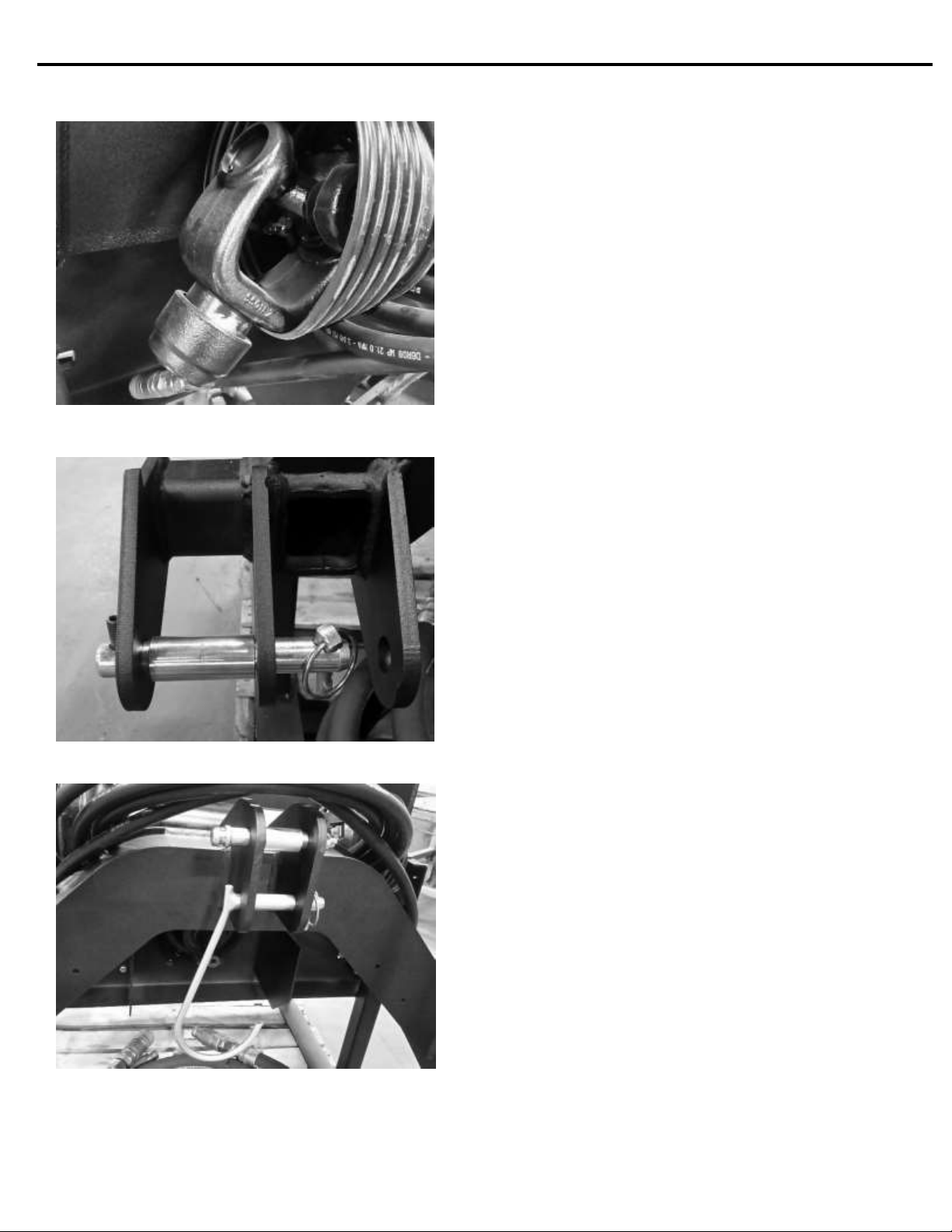
2. Slide the driveline fully onto the tractor PTO shaft.
Make sure the locking collar is engaged. If the
tractor PTO shield interferes with the installation,
the shield may need to be removed or rotated up.
Always reinstall the PTO shaft
shield when the PTO pump is not connected to
the tractor. See the tractor’s operator’s
manual for instructions.
3. Check to make sure the driveline has enough
overlap and does not bottom out through the
entire range of movement of the 3-point arms. If
the driveline is too short or too long, the 3-point
mount frame can be moved fore or aft by unbolting
and sliding it. There are three different positions
available, each 2” apart.
NOTE: It may be necessary to reposition or
remove the drawbar to prevent interference with
the driveline. See the tractor’s operator’s manual
for instructions.
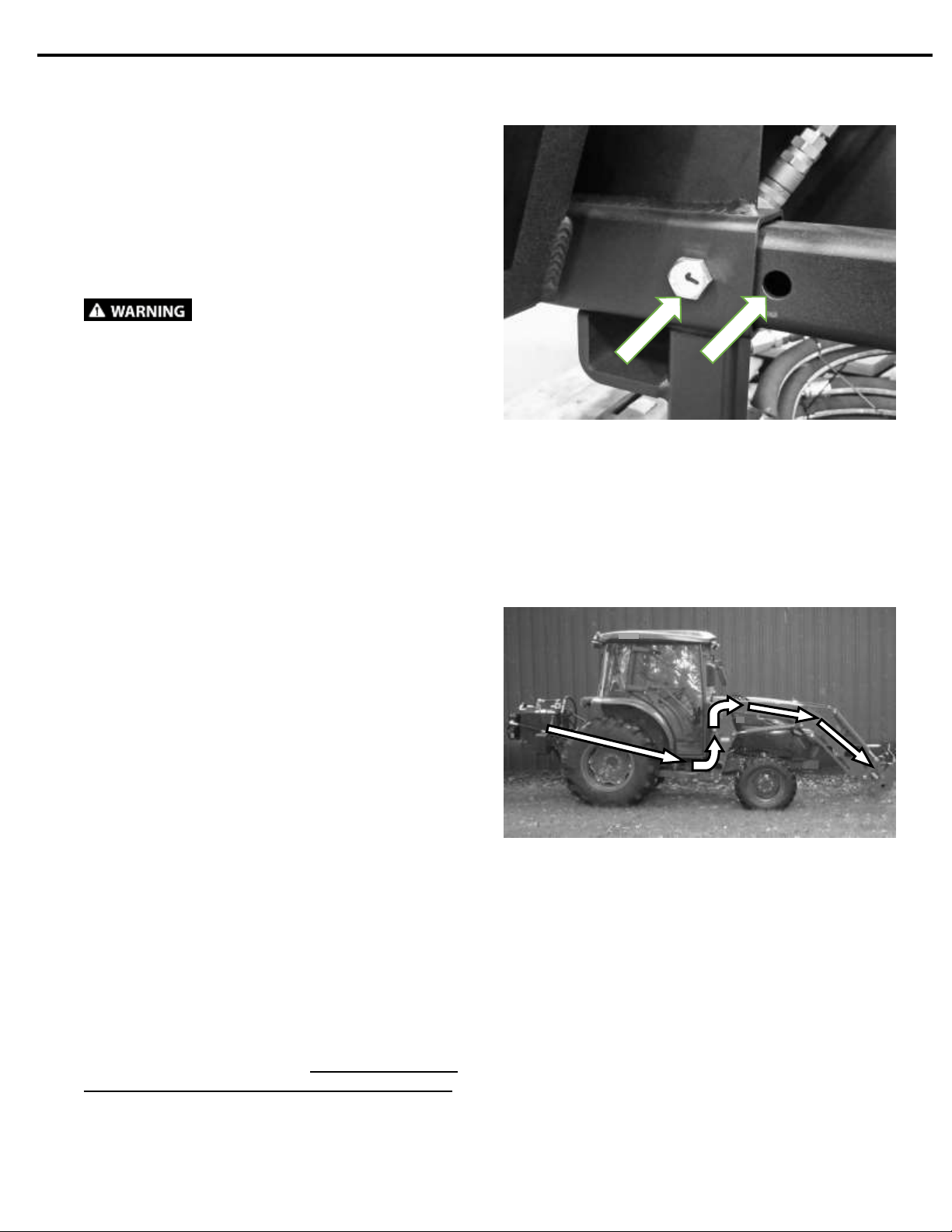
4. Route the lead hoses over the rear axle, underthe
tractor cab, and along the loader arms. Use
plastic cable ties to mount the hoses to the tractor
frame and loader arms.
IMPORTANT: Be sure to route the hoses near
the loader pivot points to prevent the hoses from
being stretched when the loader is raised.
NOTE: Make sure the hoses are properly routed
to fit your specific tractor. If the hoses are not
routed correctly, they may get pinched, stretched,
pulled off, or rub on tires. Be sure to check hose
routing through the full range of motion of the
loader and attachment before operating. More
than one routing may beacceptable depending on
the tractor. Use the routing that best fits your
tractor.
NOTE: Proper hose routing is the responsibility
of the owner and/or operator. Pinched, rubbed, or
stretched hoses are not covered under warranty.

9
MOUNTING INSTRUCTIONS
Oil Grade Selection
Use the proper oil grade for the weather conditions
anticipated during operation.
Cold: -20°F to 40°F (-29°C to 4°C)
Use ISO 32 (10W) or less hydraulic fluid (full synthetic
strongly recommended). Alternate: 10W-30 motor oil
or ATF.
Automotive type crankcase oils with American
Petroleum Institute (API) letter designations SE, SF,
SG, SH or higher (per SAE J183) classes of oils are
acceptable. These types of oils generally exhibit less
shear stability, which can result in higher loss of
viscosity during service life.
IMPORTANT: Incold weather, always preheat the oil
using the supplied 1000W oil heater to prevent pump
cavitation. Run the PTO pump at low speed for at
least 15 minutes to warm the system up to at least
50°F before operating under load.
Warm: 40°F to 100°F (4°C to 38°C)
Use ISO 32 (10W) or greater.
NOTE: See page 25 for oil viscosity information.
5. Route the cooler fan wire harness to the tractor
battery. Connect the red (fused) wire to the
positive (+) terminal of the battery and the black
wire to the negative (-) terminal of the battery.
IMPORTANT: Make sure the fuse is operational
and rated for a minimum of 40 amps.
6. Connect the rear set of hydraulic quick couplers to
the lead hoses, and the cooler fan wire harness to
the cooler fan connector.
IMPORTANT: Make sure the quick couplers are
fully engaged. If couplers will not engage, do not
force quick couplers together.
NOTE: Attachment is shipped with 16FJX
(1-5/16” Female JIC Swivel) fittings on the ends of
the lead hoses.
7. Check all fittings to make sure they are tight.
8. Fill the tank with the correct grade of NEW
hydraulic oil (or other approved fluid) until the oil
level is centered in the sight gauge on the left side
of the tank. The tank capacity is 33 gallons (125
L), but up to an additional 3 gallons (11.4 L) may
be needed to fill the hoses and attachment.
9. Connect the two lead hoses together at the front
of the loader and test run the pump at low speed
to check for leaks and to flush the system.
IMPORTANT: Do not flush the system with the
lead hoses connected to an attachment or
contamination may become lodged in the
attachment system.
10. Run the system at full throttle for at least 15
minutes to flush the system of any possible
contamination.
IMPORTANT: Always engage the PTO drive with
the engine at low speed. This is especially
important during cold weather start-ups.
11. Mounting is now complete and the PTO pump is
ready for operation.

10
OPERATING INSTRUCTIONS
1. With the operator in the seat of the tractor and the
seatbelt fastened, start the engine.
2. Raise the 3-point arms until the driveline is
relatively straight and the legs have adequate
clearance with the ground.
3. Connect the lead hoses to an attachment
mounted on the front of the tractor.
4. With the engine at low speed, engage the tractor
PTO drive.
IMPORTANT: Engine must be at idle speedwhen
engaging PTO drive.
5. Run the PTO pump at low speed for at least 15
minutes to warm the oil and check the system for
leaks. A 1000W oil heater is installed in the tank
and should be plugged in if the tank is not stored
inside a heated building.
6. Once the oil has reachedat least 50°F, throttle the
tractor engine up to working RPM.
IMPORTANT: Never operate the PTO pump at a
PTO speed exceeding 600 RPM. This will
damage the PTO pump and void all warranties.
NOTE: The PTO pump will produce the rated flow
rate and pressure when the tractor PTO is run at
standard 540 RPM. Most tractor PTO’s will run at
a slightly higher RPM at full throttle. It is
acceptable to run the tractor at full throttle.
7. Operate the attachment as described in the
attachment’s operator’s manual.
IMPORTANT: Never operate the PTO pump with
an attachment that is not rated for at least 35 GPM
and 4000 PSI.
8. There is a small LED light on the cooler wire
harness that will light up when the thermostat
turns on the cooler fan. This tells the operator that
the cooler fan is operating. The thermostat is set
at 115°F (46°C).

11
OPERATING INSTRUCTIONS
Oil Temperature and Duty Cycle Information
Heat is the enemy of every hydraulic system. Every
hydraulic system is susceptible to overheating, even
when operating in subzero temperatures.
While every precaution has been taken to ensure a
reliable system, the operator has a responsibility to
operate the system within the design limits.
IMPORTANT: The maximum allowable oil
temperature is 180°F (82°C).
Above this limit, the oil viscosity can be reduced to the
point where it will not lubricate the pump sufficiently,
leading to system failure.
The oil temperature is a function of the amount of time
the system is working, versus the “rest” time (running
but not working). The ratio of work time compared to
total run time is called the duty cycle.
Example: A machine with a duty cycle of 50% is
meant to work 5 minutes out of every 10 minutes.
The following duty cycles only apply to systems
operating in ambient air temperatures from 0°F to
40°F (-18°C to 4°C).
HP35 –75% duty cycle maximum
At ambient air temperatures above 40°F the duty
cycle is reduced.
A thermometer is located on the front side of the tank
to make monitoring oil temperature more convenient.
Things to DO while operating:
•Monitor the system for leaks.
•Monitor the cooler harness LED (if equipped) to
ensure that the fan is operating.
•Monitor the system temperature if the cooler LED
light stays lit continuously.
•Make sure the cooler is free of dirt and debris for
maximum cooling capacity.
Things to AVOID while operating:
•Prolonged stalling of the attachment.
•Operating for extended periods of time at
maximum power.
•Operating with the cooler fan harness
disconnected.
•Operating the power unit with a low oil level.

12
ROUTINE MAINTENANCE___________________
Lower the attachment to rest on the ground, disengage the PTO, set the park brake, shut
down the engine, remove the key, and wait for all motion to stop before leaving the operator’s seat to
perform service of any kind.
It is the operator’s responsibility to make daily inspections of the attachment and tractor for damage, loose bolts,
fluid leaks, or anything else that could cause a potential service or safety problem. Preventive maintenance is
the easiest and least expensive type of maintenance.
IMPORTANT: Bolts and set screws can loosen after initial usage. After first hour of operation check all bolts
and set screws.
Cooler Maintenance
Make sure the oil cooler is clean and free of debris
before operating the power unit. If dirty, clean the
cooler fins by flushing them with clean water or
blowing it out with compressed air.
Wear safety gasses meeting ANSI
z87.1 standard when cleaning with water pressure
or compressed air.
IMPORTANT: The filterelement (P/N 310999) should
be replaced after the first 50 hours of operationor after
1 year, whichever comes first. Thereafter, it should
be replaced after every 250 hours of operation or after
every 3 years, whichever comes first. More frequent
filter changes may be required based on operating
conditions.
1. Remove the cover bolts with a 10mm socket and
remove the cover.
NOTE: To prevent contamination, wipe the area
around the filter clean before removing the cover.
2. Remove the filter element from the plastic can.
3. Install the new filter element.
4. Reinstall the cover and bolts. Tighten bolts to
maximum 7 ft-lbs. Do not overtighten.
IMPORTANT: Improper maintenance can cause
extensive damage to the power unit, attachment,
and your equipment.
Oil Change Interval
•Change the hydraulic oil every 250 hours or every
3 years, whichever comes first. More frequent
changes may be required based on operating
conditions. Be sure to replace with the correct
grade and type of oil for the expected operating
conditions.
•The drain plug is locatedon the bottom of thetank.
Tighten the plug after the old oil is drained. Check
for leaks after new oil has been added.
•Change the gearbox lube every 250 hours or
every 3 years, whichever comes first. Fill to
between 1/3 and 1/2 full (approximately 38 oz.)
with 80W-90 gear lube.

13
BOLT TORQUE INFORMATION

14
PTO PUMP HF PARTS INFORMATION
ITEM
QTY
PART NO.
DESCRIPTION
STOCK NO.
1
1
423900
TANK PTO 36 GAL W/A
2
1
423901
FRAME PTO PUMP HF W/A
3
1
423946
BRKT COVER REAR PAINTED
4
1
330864
HOLDER MANUAL CANISTER 12.5 X 2.25
5
1
423928
VALVE ASSM RELIEF 4000 PSI
6
2
13053
BOLT HEX
5/16 X 3/4 NC GR 5
7
10
103880
WASHER LOCK
3/8"
8
2
36304
NUT HEX FULL
5/16 NC GR5 Z
9
2
13064
BOLT HEX
5/16 X 2-3/4 NC GR 5
10
2
37211
NUT REV LOCK
5/16 NC GR A Z
24
10
13105
BOLT HEX
3/8 X 1 NC GR 5

15
PTO PUMP HF PARTS INFORMATION

16
PTO PUMP HF PARTS INFORMATION
ITEM
QTY
PART NO.
DESCRIPTION
STOCK NO.
1
1
423902
MOUNT 3PT CAT 2/3 W/A
2
1
423923
COOLER HD D20 PTO PUMP HF
3
1
423939
BRKT SHIELD DRIVELINE PAINTED
4
1
423922
GEARBOX PLANETARY 1:3.92 6T-15T
5
1
423924
PUMP 3.84 CID SAE B 4-B PISTON
6
1
423957
DRIVELN 55S 6T X 6T X 33
7
1
310998
FILTER IN TANK W/ELEMENT 10 MICRON LONG
8
1
310999
FILTER ELEMENT 10 MICRON 8.3"
9
1
310940
FILLER BREATHER TANK 6 IN
10
1
310974
O-RING 4 X 3/32 (-155)
11
1
300583
PIN 3-PT CAT1 LOWER 7/8 X 5
12
1
300460
PIN 3-PT CAT1 TOP 3/4 X 3-7/8
13
1
420069
BUSH 1.10 X .91 X 2.5 Z
14
1
420070
BUSH 1 X .78 X 1.69 Z
15
1
420420
HOOK PIN DRIVELINE W/A Z
16
4
104432
PIN LYNCH 7/16 X 1-3/4
17
1
423916
THERMOMETER STR 5 OD -6 L-1/2 NPT
18
2
13319
BOLT HEX
5/8 X 4 NC GR 5
19
2
37216
NUT REV LOCK
5/8 NC GR A Z
20
6
13117
BOLT HEX
3/8 X 3-1/2 NC GR 5
21
4
37212
NUT REV LOCK
3/8 NC GR A Z
22
4
22876
BOLT FLG 12PT
1/2 X 1-1/2 NC Z
23
4
13055
BOLT HEX
5/16 X 1 NC GR 5
24
4
13105
BOLT HEX
3/8 X 1 NC GR 5
25
4
33620
WASHER LOCK
5/16"
26
4
13057
BOLT HEX
5/16 X 1-1/4 NC GR 5
1
310932
THERMOSTAT 115F

17
PTO PUMP HF PARTS INFORMATION

18
PTO PUMP HF PARTS INFORMATION
ITEM
QTY
PART NO.
DESCRIPTION
STOCK NO.
1
1
423950
HOSE 1 X 26 16FJX-16FJX-90 (3000 PSI)
2
1
423923
COOLER HD D20 PTO PUMP HF
3
1
423941
HOSE 1 X 240 16FJX-16FJX (4000 PSI)
4
1
423943
COUPLER HYD 3/4-16OR FM FF
5
1
423944
COUPLER HYD 3/4-16OR M FF
6
1
300661
ADPT ELB 16MB-16MJ-90
7
2
201528
ADPT STR 16MB-16MJ
8
1
423929
ADPT STR 16MB-16MB

19
PTO PUMP HF PARTS INFORMATION

20
PTO PUMP HF PARTS INFORMATION
ITEM
QTY
PART NO.
DESCRIPTION
STOCK NO.
1
1
423928
VALVE ASSM RELIEF 4000 PSI
2
1
423949
HOSE 3/4 X 21 12FJX - 12FJX (3000 PSI)
3
1
423941
HOSE 1 X 240 16FJX-16FJX (4000 PSI)
4
1
423943
COUPLER HYD 3/4-16OR FM FF
5
1
423944
COUPLER HYD 3/4-16OR M FF
6
1
423952
HOSE 1/2 X 260 8FJX-8FJX
7
1
201528
ADPT STR 16MB-16MJ
8
1
423929
ADPT STR 16MB-16MB
9
1
330773
ADPT ELB 16MB-12MJ-90
10
1
318897
ADPT BUSH 12MB-8FB
11
1
423955
ADPT ELB 8MB-8MB-90
12
1
201934
COUPLER HYD 3/8-8OR M FF
13
1
201933
COUPLER HYD 3/8-8OR FM FF
14
1
300273
ADPT STR 8MB-8MJ
15
1
300262
ADPT ELB 12MB-12MJ-90
Table of contents
Popular Portable Generator manuals by other brands

Husqvarna
Husqvarna PP490 Operator's manual

Monacor
Monacor Security PS-12WP Mounting instructions

Champion
Champion 201174 Operator's manual

Master
Master MGH3000G OWNER'S OPERATION AND INSTALLATION MANUAL

Simplicity
Simplicity 990220 Operator's manual

Domnick Hunter
Domnick Hunter Maxigas Series Service guide

Champion
Champion 201155 quick start guide

Powermate
Powermate PMC435003 owner's manual

pcl
pcl NEXUS Series user manual

Champion Global Power Equipment
Champion Global Power Equipment 100891 Operator's manual

Rohde & Schwarz
Rohde & Schwarz R&S AREG800A user manual

Platinum Tools
Platinum Tools ToneMaster TG210 User instructions