Ersted RI-407 User manual

TIME DOMAIN REFLECTOMETER
Model: RI-407
USER MANUAL
Saint-Petersburg
2016 г.

Safety Information
Implemented Measurement Methods
Time Domain Reflectometer RI-407 User Manual Page 2 of 67
Safety Information
ATTENTION!
Before you start please check out the User Manual carefully
DANGER: - High Voltage!
The device should only be used by a
qualified personnel
The operator of the device must comply with all safety precautions listed in this User Manual
in order to ensure own safety and the safety of other people in the work area immediate vicinity.
Mishandling can result in serious injury or death.
The device has an open inputs.
When you connect the RI-407, make sure that there is no
voltage on the line.
Software User Manual to communicate RI-407 with the PC can be found on the CD.

Designations and Contractions
Implemented Measurement Methods
Time Domain Reflectometer RI-407 User Manual Page 3 of 67
1. Designations and Contractions
HVPG - high-voltage pulse generator
PF – Propagation Factor
HVL - High-voltage testing laboratory
PC – personal computer
UM – User Manual
TC – technical conditions
MC – measuring channel
MEC – memory channel

Introduction
Implemented Measurement Methods
Time Domain Reflectometer RI-407 User Manual Page 4 of 67
2. Introduction
This UM is a document certifying guaranteed by the manufacturer the basic parameters and
technical characteristics of the time domain reflectometer RI-407 (hereinafter the RI-407).
UM is intended for acquaintance with the RI-407 device and the principle of operation and
sets the operating rules, compliance with which maintains the device in constant readiness for action.
Persons with secondary technical education are admitted to work with the device, with
experience in electrical appliances for general purposes.

Application Area
Implemented Measurement Methods
Time Domain Reflectometer RI-407 User Manual Page 5 of 67
3. Application Area
RI-407 is intended for the following measurements on balanced and unbalanced cables:
cable length measurement and cable continuity tests;
measurement of the distance to the heterogeneity of the cable impedance or low-resistance fault,
using the pulse (TDR) method;
measurement of the distance to the high-resistance fault, using the Arc Reflection Method (ARM)
in complex with the high-voltage pulse generator (HVPG) (Arc Discharge Generator ADG-200
or similar generator from the high-voltage test laboratory);
measurement of the distance to the high resistivity fault, using the Impulse Current Method
(ICM) or Decay Method in complex with the high-voltage pulse generator (HVPG) (Arc
Discharge Generator ADG-200 or similar generator from the high-voltage test laboratory);
measurement of the velocity factor of the line at a known length;
determination of fault’s nature;
recording into internal storage and playback of at least 300 waveforms for subsequent processing
in stationary conditions;

Specifications and Characteristics
Implemented Measurement Methods
Time Domain Reflectometer RI-407 User Manual Page 6 of 67
4. Specifications and Characteristics
Measurement results are displayed on the color TFT screen with a resolution of 640 x 480
pixels.
Distance measuring range (time delay) from 0 to 128000 m (from 0 to 1280 µs).
Measuring sub-ranges:
0 – 62,5 m (0 – 0,625 µs); 0 – 125 m (0 – 1,25 µs); 0 - 250 m (0 – 2,5 µs);
0 - 500 m (0 -5 µs); 0 - 1000 m (0 - 10 µs); 0 - 2000 m (0 - 20 µs);
0 - 4000 m (0 - 40 µs); 0 - 8000 m (0 - 80 µs); 0 - 16000 m (0 - 160 µs);
0 - 32000 m (0 - 320 µs); 0 - 64000 m (0 - 640 µs), 0 - 128000 m (0 - 1280 µs).
Measurement permissible relative error of the distance (time delay) in the normal range of
temperatures from 15 °C to 25 °C are ± 0.2% of the sub-range value.
Measurement permissible relative error of the distance (time delay) in the operating range of
temperatures from -20 to 15 °С and from 25 to 40 °С are ± 0,4 % of the sub- range value.
Probing pulse parameters with positive polarity are shown in Table 2-1.
Table 2-1
Probing pulse
parameters
Pulse
10 ns
20 ns
50 ns
100 ns
200 ns
500 ns
1 µs
2 µs
5 µs
10 µs
20 µs
50 µs
100 µs
τи, µs
≤ 0,01
≤ 0,02
≤ 0,05
0,1 ±
0,01
0,2 ±
0,02
0,5 ±
0,05
1,0 ±
0,01
2 ±
0,2
5 ±
0,5
10 ±
1,0
20 ±
2,0
50 ±
5,0
100 ±
10,0
Τн, ns,
no more than
10
10
15
15
20
20
25
30
30
30
30
30
30
U1, В, not less than
9,0
9,0
9,0
9,0
9,0
9,0
9,0
9,0
9,0
9,0
9,0
9,0
9,0
U2, В, not less than
*
43,0
43,0
43,0
43,0
43,0
43,0
43,0
43,0
43,0
43,0
43,0
*
* Note: The parameters of the probe pulse in U2 mode, with durations 10 ns and 100 µs are not
standardized.
Measurement relative error of the Propagation Factor (PF) ± 0,4% in the range of PF value
from 1.000 to 3.000.
Receiver sensitivity in all sub-bands of at least 10 mV (provided that signal level is twice
noise level)
Asynchronous noise suppression - averaging 1 to 64.
Non-volatile memory capacity - traces of at least 300, at least 500 velocity factors.
Measuring input impedance TDR - 75 ohms (fixed).
Operation mode setup time less than 15 seconds.

Specifications and Characteristics
Implemented Measurement Methods
Time Domain Reflectometer RI-407 User Manual Page 7 of 67
Continuous running RI-407 from the battery ACC1 at least 6 hours (or at least 10 hours from
the battery ACC2) and depends on the condition of the battery. Continuous running via AC
adapter is not limited.
Maximum electric power consumed by the RI-407 while charging the battery, not more than
40 W.
Overall dimensions of the RI-407 is not more than:
length - 363 mm
width - 295 mm
height - 170 mm
Weight of RI-407 with built-in battery no more than 3.5 kg
RI-407 is a compact device designed to work in indoor and outdoor conditions. RI-407 meets
climatic conditions Group 4 GOST 22261:
operating temperature range from -20 to 40 °C;
relative humidity 98%, at 25 °C;
transportation and storage conditions from -50 to 50 °C.
RI-407 is stable and resistant to the sinusoidal vibration in frequency range from 10 Hz to 55
Hz. RI-407 meets conditions Group 4 GOST 22261.
RI-407 is powered by the built-in Li-Ion battery (7,2 ± 0,7)V 7,0A. The design of the RI-407
provides control of battery discharge and automatic device shut down in 2, 4, 8, 32 or 64
minutes of idle time.
RI-407 does not emit toxic gases and audio noise.
Reliability:
MTBF - at least 6000 hours.
Service life - at least 5 years.

Delivery Contents
Implemented Measurement Methods
Time Domain Reflectometer RI-407 User Manual Page 8 of 67
5. Delivery Contents
The set of RI-407 includes:
Quantity
Time Domain Reflectometer RI-407 (tech. spec. 4221-009-23133821-15)
1 item
AC Adapter 12 V
1 item
Connecting cable 75 Ohm, 3 m, BNC.M - «Alligator» with a working width
of 25.4 mm
1 item
Connecting cable 75 Ohm, 1 m, BNC.M-BNC.M
2 items
User Manual (tech. spec. 4221-009-23133821-15)
1 item
CD-ROM with software
1 item
Accessories bag
1 item

Design And Implemented Measurement Methods
Implemented Measurement Methods
Time Domain Reflectometer RI-407 User Manual Page 9 of 67
6. Design And Implemented Measurement Methods
6.1. Implemented Measurement Methods
6.1.1. Time Domain Reflectometry (TDR) Method
The instrument uses a Time Domain Reflectometry method (TDR), which is based on the
phenomenon of a partial reflection of electromagnetic waves by the impedance irregularities in the
line. When applying the TDR method a rectangular probe pulse generated by the pulse generator is
sent into the line. Probe pulse propagating through the cable line, completely or partly reflected from
the fault area in the line (impedance irregularities) and returns to the receiver input. Reflection
waveform is observed on the screen and allows to determine the type of the fault (see Table 6-2) and
the distance to it. The reflected pulses are returned to the device after a certain time from the moment
of sending the probe pulse.
Knowing the speed of electromagnetic wave propagation along the line, and the time delay of
the reflected signal (measured by the device), we can calculate the distance to the impedance
irregularity.
here,
L – Distance to the impedance irregularity, m.
v – Propagation speed of electromagnetic wave in the line, m/µs;
PF – Propagation Factor, c/v
VoP – Velocity of Propagation , (v/c)*100%
td – Measured time delay of the reflected signal, µs;
с – Speed of light is equal to 299,8 m/µs;
Impedance irregularities are the result of violations manufacturing technology of cables as
well as a consequence of mechanical and electrical hazards during the construction and operation of
the cable lines. Any cable device (couple, split, joint, Pupin coil, etc.) cause irregularity of the line
impedance.
21002
1
2ddd t
VoP
c
t
PF
c
t
L
Design And Implemented Measurement Methods
Implemented Measurement Methods
Time Domain Reflectometer RI-407 User Manual Page 10 of 67
The impedance irregularities may be caused by any cable devices (couple, joint, Pupin coil,
etc.) or faults (open, short, partial open, partial shot, wetting core of the cable, leaks to the ground,
split pairs, etc.). TDR method allows to fix multiple irregularities both lumped and lengthy,
depending on the ratio of their length and the minimal wavelength of the spectrum of the probe
pulse.
The instrument generate a probe pulse with positive polarity amplitude is not less than 10V
(U1 mode), or not less than 45V (U2 mode) (see Table 4-1). The probe pulse width is automatically
adjusted according to the selected sub-range (see Table 6-1). Furthermore, pulse width can be set
manually by the user.
RI-407 automatically calculates the distance, according to the velocity factor and
measurement cursors positions on the screen. The distance measurement error is determined by the
sampling step of the instrument and by the velocity factor setting error.
Sampling step for each sub-range is set by default in such a way that the viewing window got
whole sub-range used by (see. Table 6-1). Sampling step can be adjusted (reduced or increased)
manually by the operator to minimize the instrumental error.
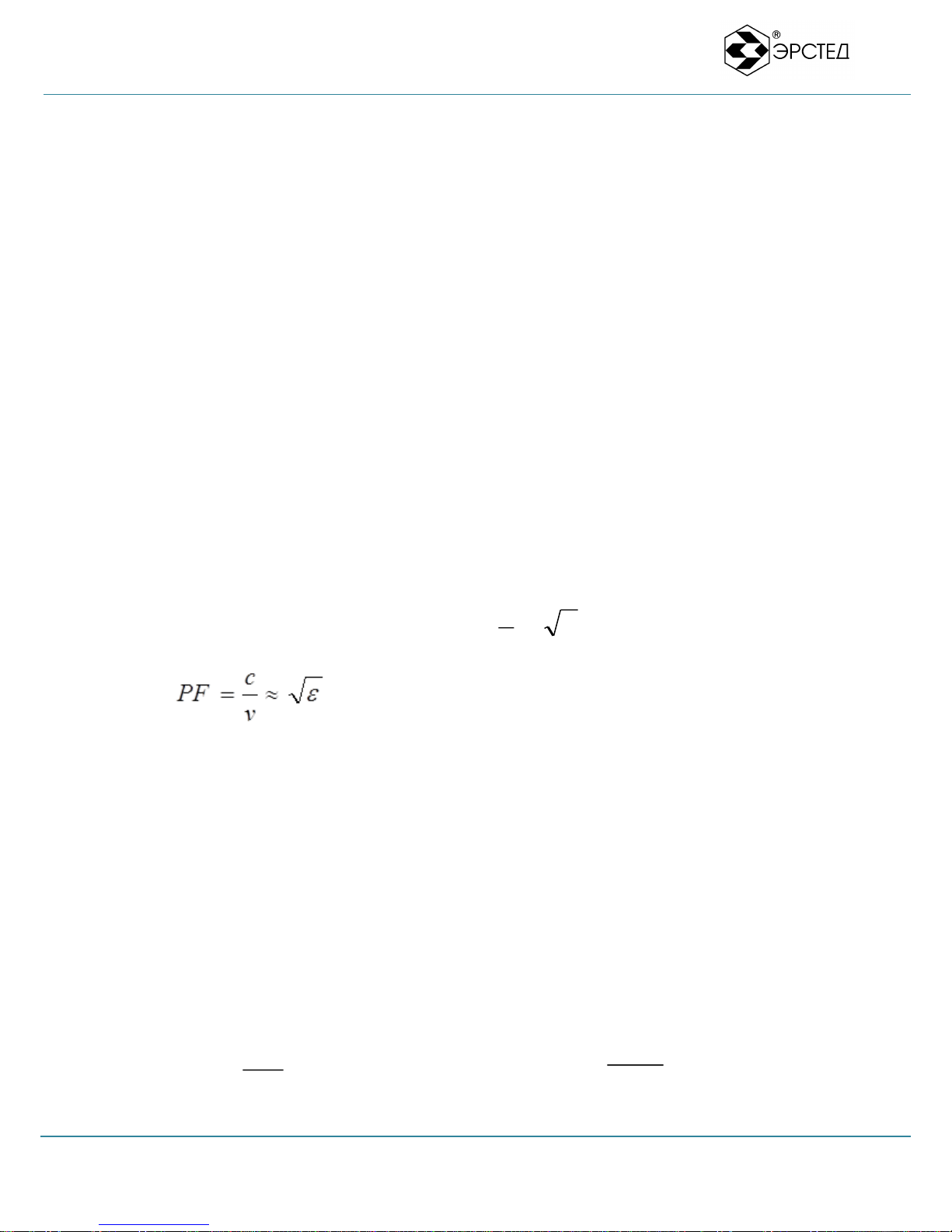
The velocity factor value is depends of the type of cable.
here,
PF – Propagation Factor;
v – Propagation speed of electromagnetic wave in the line, m/µs;
с – Speed of light is equal to 299,8 m/µs;
ε – Dielectric constant of the cable insulation.
Propagation speed can be determined experimentally, knowing in advance the distance (L) to
any irregularity (e.g., cable length or distance before the coupling). In this case, the inverse problem
is solved that way:
v
с
PF
3
2t
L
с
PF
3
2tL

Design And Implemented Measurement Methods
Implemented Measurement Methods
Time Domain Reflectometer RI-407 User Manual Page 11 of 67
Additional errors are due to the distortion of the reflected signal in the lines with a frequency-
dependent losses. The measurement error affects the nature of irregularity, its value, the existence of
several irregularities in the line.
Table 6-1 Sub-bands-measurement range
Sub-range, m
Default pulse width, ns
Sampling step, m
PF=1.5 (VOP=66%)
Minimal sampling step, m
PF=1.5 (VOP=66%)
0 – 62,5
10
0,125
0,125
0 – 125
10
0,250
0,125
0 – 250
20
0,500
0,125
0 – 500
50
1,000
0,125
0 – 1000
100
2,000
0,250
0 – 2000
200
4,000
0,500
0 – 4000
500
8,000
1,000
0 – 8000
1000
16,000
2,000
0 – 16000
2000
32,000
4,000
0 – 32000
5000
64,000
8,000
0 – 64000
10000
128,000
16,000
0 - 128000
20000
256,000
32,000
Design And Implemented Measurement Methods
Implemented Measurement Methods
Time Domain Reflectometer RI-407 User Manual Page 12 of 67
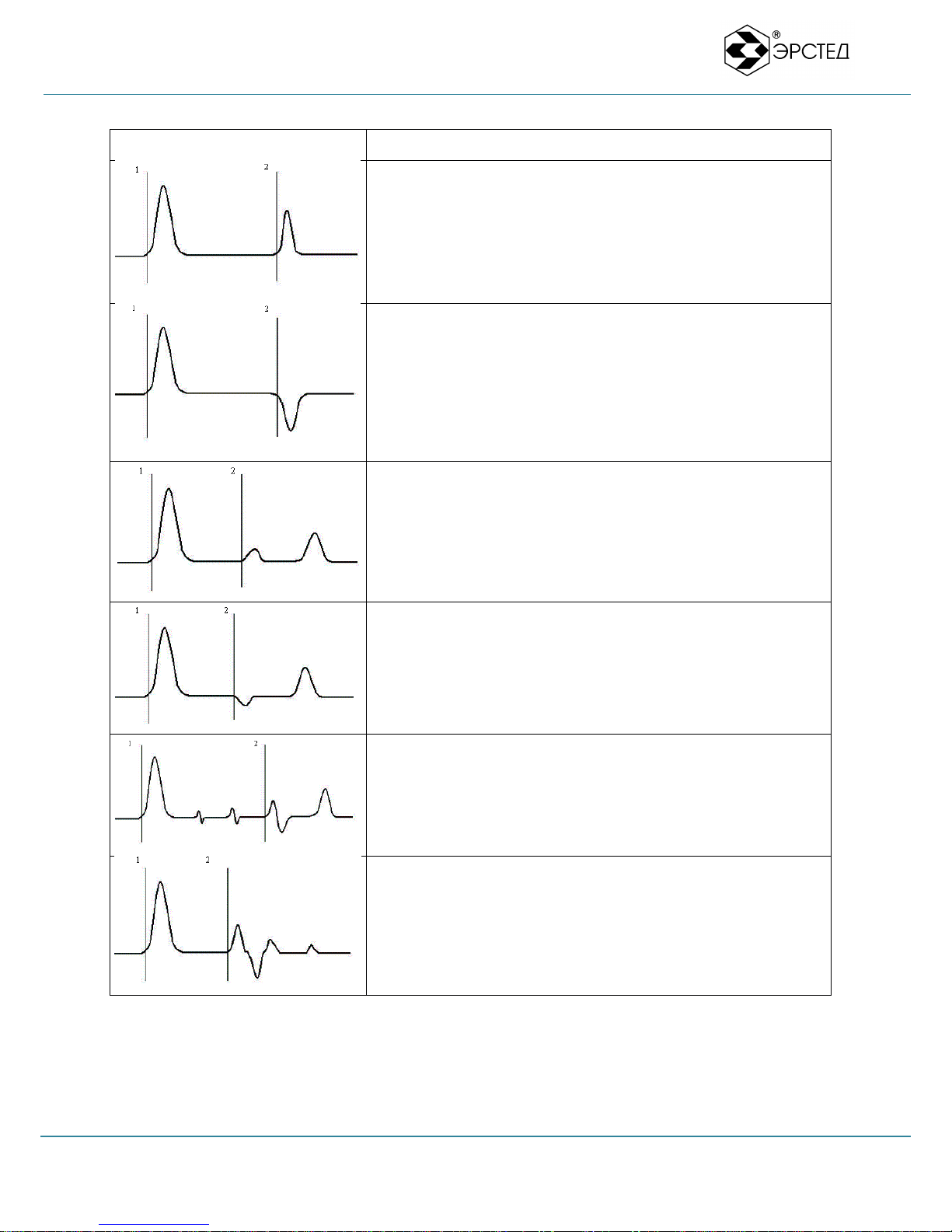
Table 6-2 Waveforms of the typical irregularities.
Waveform
Description
The first cursor points to the probe pulse.
The second cursor points to the reflection from irregularity with
high impedance, which corresponds to the cable break
(COMPLIT OPEN).
The first cursor points to the probe pulse.
The second cursor points to the reflection from irregularity with
low impedance (reflection with inversed signal polarity), which
corresponds to a short circuit in the cable (DEAD SHORT).
The first cursor points to the probe pulse.
The second cursor points to the reflection from irregularity with
increased impedance, followed by a complete cable break.
(PARTIAL OPEN)
The first cursor points to the probe pulse.
The second cursor points to the reflection from irregularity with
decreased impedance, followed by a complete cable break
(PARTIAL SHORT).
The first cursor points to the probe pulse.
The current waveform shows three joints on a cable. A joint,
marked by the second cursor is defective, it can be clearly seen
on the level of reflection.
The presence of a faulty amplifier in the line results an increased
reflection from the amplifier. The signal must terminate on the
amp, but it’s possible an additional reflection (phantom) of the
amplifier.

Design And Implemented Measurement Methods
Implemented Measurement Methods
Time Domain Reflectometer RI-407 User Manual Page 13 of 67
Couplers in the cable can cause measurement errors due to
multiple reflections. On the waveform cursor marks the coupler.
Two differently directed reflected signals indicate the two
segments of the coupler.
Additional resistance or weld rise to an S-shaped reflection on the
trace. Reflection from increased impedance followed by
reflection from decreased impedance.
Well matched cable including cable terminator fully absorbs
signal reflections. This waveform guarantees the normal cable
terminator choice, which does not cause reflection.
Wet cable is recognized as an area with the random reflection. The
beginning of this area shows a second cursor corresponds to the
beginning of the wet region.
Increasing humidity in the cables leads to the appearance of the noises
in the waveform.
Note to Table 6-2: The amplitudes of the pulses are given in the appropriate proportions at the
same amplification.
Design And Implemented Measurement Methods
Implemented Measurement Methods
Time Domain Reflectometer RI-407 User Manual Page 14 of 67
6.1.2. Arc Reflection Method (ARM)
Localization of the cable faults with a high transient resistance (R>10 kOhm) is usually
difficult when using low-voltage TDR method. One of the ways for localization such defects in
power cables is an Arc Reflection Method (ARM).
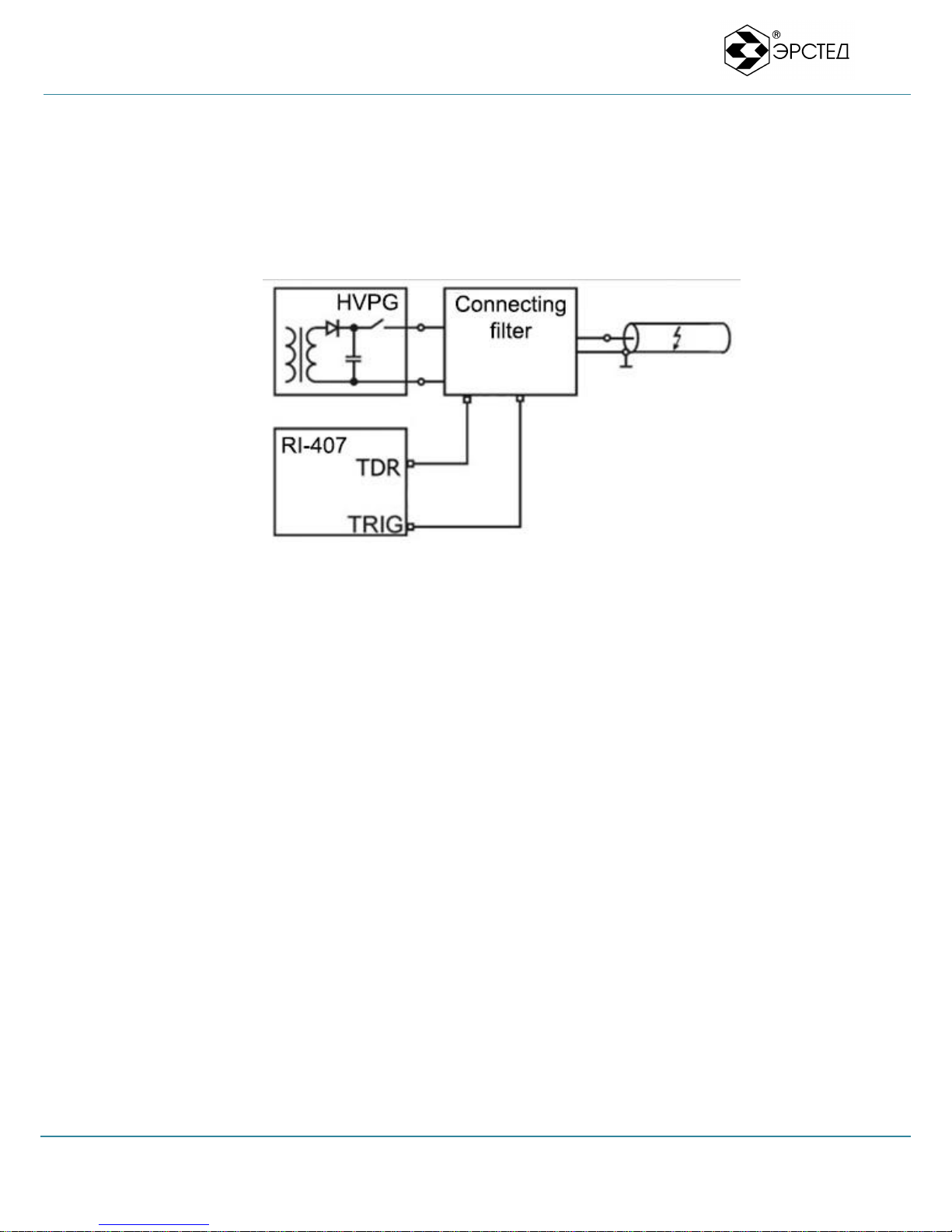
Picture 6.1 Diagram of the implementation of an Arc Reflection Method
Implementation of ARM method is carried out with the additional equipment: high-voltage
pulse generator (HVPG) and the special connecting device (as an external unit or internal HVPG
unit).
The essence of the ARM method is in creating conditions (using HPVG) for the occurrence
electric arc (breakdown) for a short time (few milliseconds) in the point of the fault. Synchronously
with the burning arc (sync signal obtained from HPVG) reflectometer performs sensing. The TDR’s
probe pulse is reflected from a low resistance of the arc with inverted polarity (like shorted circuit).
For easy identification of the fault location, waveform without breakdown (high transient
resistance at the point of the defect) and waveform during breakdown (low transient resistance at the
point of the defect) are compared.
Design And Implemented Measurement Methods
Implemented Measurement Methods
Time Domain Reflectometer RI-407 User Manual Page 15 of 67
6.1.3. Oscillatory Discharge Methods (ODM)
Localization of the cable faults caused self-healing insulation breakdown is usually difficult
when using low-voltage TDR method. One of the ways for localization such defects in power cables
is an Oscillatory Discharge Methods (ODM): Impulse Current Method (ICE) and Decay travelling
wave method (DECAY).
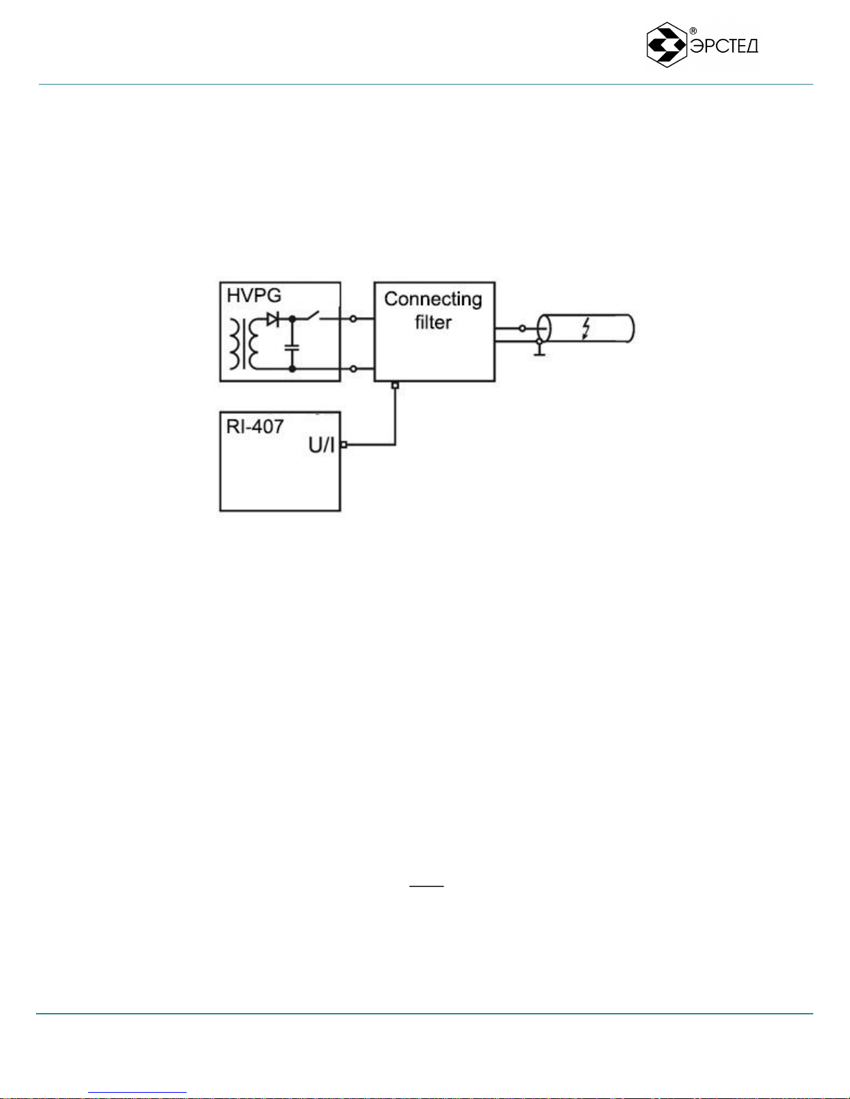
Picture 6.2 Diagram of the implementation of an Oscillatory Discharge method
The methods of oscillatory discharge (ICE, DECAY) are based on the measuring period of
oscillatory processes occurring in the breakdown of the charged cable. Implementation of the
methods is carried out using the optional equipment: the high-voltage pulse generator (HVPG) and a
special connecting device (as an external block or internal HVPG unit).
The essence of the method is: HVPG raises voltage in the cable until the breakdown
occurred. The defect causes a breakdown of the insulation at the site of the fault, causing a spark,
which has low resistance and the oscillatory discharge in the cable occurs. Knowing the speed of
electromagnetic wave propagation (v) in the line and the period of oscillation process (Top), we can
calculate the distance to the breakdown (L):
To achieve the highest accuracy only the first oscillation period is selected.
2
op
T
L

Design And Implemented Measurement Methods
Product View
Time Domain Reflectometer RI-407 User Manual Page 16 of 67
6.2. Product View
The product view is provided on the Figure 6-3.
Figure 6-3 RI-407 Product View

Design And Implemented Measurement Methods
Interface Controls
Time Domain Reflectometer RI-407 User Manual Page 17 of 67
6.3. Interface Controls
6.3.1. Overview
All controls and connectors of the instrument are located on the front panel, shown in Figure 6-4:
a) Display (par. 6.3.3) - color TFT screen with a resolution of 640 x 480 pixels;
b) "Reset" button is designed to forcibly turn off the power of the instrument;
c) 24 -Button keypad (tab. 4-4) for controlling the device via the GUI;
d) Input / Output BNC Connectors, 3 х 75 ohm female (par. 6.3.2);
e) USB socket – provides socket for data exchange and additional devices;
f) Charge Connector – provides DC -12 V socket to the instrument charge adapter;
g) Charge Indicator – provides charging status of battery through LED indication.
Figure 6-4 RI-407 front panel.

Design And Implemented Measurement Methods
Interface Controls
Time Domain Reflectometer RI-407 User Manual Page 18 of 67
6.3.2 Connectors
All connectors of the instrument are located on the front panel:
TDR connector (input/output, 75 ohm, BNC female) - for connecting the instrument to the
cable either directly or through the appropriate HPVG socket (TDR socket on ADG-200);
TRIG connector (input, 75 ohm, BNC female) - for receiving Sync signal from the
appropriate HPVG output (TRIG socket on ADG-200), when using ARM method;
WAVE connector (input, 75 ohm, BNC female) - for receiving signal from the appropriate
HPVG output (WAVE socket on ADG-200), when using ODM methods (ICE, DECAY);
Charge Connector (DC 12 V) – provides connecting with external power supply for battery
charging;
Charge Indicator – provides charging status of the internal RI-407 battery through LED
indication;
USB-A connector to connect an external USB-flash drive for data exchange.

Design And Implemented Measurement Methods
Interface Controls
Time Domain Reflectometer RI-407 User Manual Page 19 of 67
6.3.3 Display. GUI Structure Overview
The device is equipped with a TFT-display 10'' (640x480 pixels).
The upright side of the screen of the RI-407, displays internal battery status and current date
and time. The left and bottom sides displays Screen Selectors (current function of the corresponding
key "F1"-"F10" ) which are used for set and control the operating parameters of the device. In the
central part of the screen are displayed the waveforms and measurement Cursors.
The GUI structure is shown on the figure below:
Saved waveforms
management
Window
«WAVEFORMS LIBRARY»
Cables Velocity Factor
reference list
Window «CABLES PF/V2/VoP
LIBRARY»
Adjusting common instrument
settings
Window «MENU»
Button F9
(Menu)
Window «MEASUREMENT»
Channels and measurement
modes management
Window «CHANNELS»
Adjusting measurement
parameters
Window «PARAMS»
Button F10 (PARAMS)
Button F10 (CHANNELS)
Button F8
(CABLES PF LIBRARY)
Button F8
(LIBRARY)
Button Esc Button Esc
Button F10
(MEASURE)
Figure 6-5 GUI structure

Design And Implemented Measurement Methods
Interface Controls
Time Domain Reflectometer RI-407 User Manual Page 20 of 67
6.3.4 Keyboard
The RI-407 is equipped with a context sensitive keyboard (24 keys):
Table 6-3 (part 1 of 2)
Button
Functions
Turn ON/OFF the instrument.
F1 - F10
Activate the Selector, located next to the button.
In the CHANNELS window – SHIFT UP of the selected waveform.
In the PARAMS window – INCREASE the value of the active Selector: Scale, Pulse Width,
Velocity Factor, Averaging, Gain, Offset Input Delay, Threshold.
In the WAVEFORMS LIBRARY, CABLES LIBRARY and OPTIONS windows – NAVIGATE UP
through the list.
Inserts the character to the text (for example, when specifying the name of the waveform or cable in
the LIBRARY): "Space", "=", "+", "-", "1".
In the CHANNELS window and in the PARAMS window - adjustment of the waveforms
HORIZONTAL SCALE (ZOOM IN) in the area of Active Cursor.
Inserts the character to the text (for example, when specifying the name of the waveform or cable in
the LIBRARY): "_", ".", ",", ";", "2".
In the CHANNELS window and in the PARAMS window - adjustment of the waveforms
VERTICAL SCALE.
Inserts the character to the text (for example, when specifying the name of the waveform or cable in
the LIBRARY): "3","a", "b", "c".
In the CHANNELS window and in the PARAMS window – adjustment the position of the
ACTIVE CURSOR (LEFT)
Inserts the character to the text (for example, when specifying the name of the waveform or cable
in the LIBRARY): "4","d", "e", "f".
In the CHANNELS window and in the PARAMS window – SELECT the ACTIVE CURSOR (K1
or K2).
Inserts the character to the text (for example, when specifying the name of the waveform or cable
in the LIBRARY): "5","g", "h", "i".
In the CHANNELS window and in the PARAMS window – adjustment the position of the
ACTIVE CURSOR (RIGHT).
Inserts the character to the text (for example, when specifying the name of the waveform or cable
in the LIBRARY): "6","j", "k", "l".
In the CHANNEL window – SHIFT DOWN of the selected waveform.
In the PARAMS window – DECREASE the value of the active Selector: Scale, Pulse Width,
Velocity Factor, Averaging, Gain, Offset Input Delay, Threshold.
In the WAVEFORMS LIBRARY, CABLES LIBRARY and OPTIONS windows – NAVIGATE
Table of contents
Popular Measuring Instrument manuals by other brands


KRAFTWERK
KRAFTWERK 31006 instructions

Steinberg Systems
Steinberg Systems SBS-RL-500G user manual

Anritsu
Anritsu Spectrum Master MS2711D Programming manual

Endress+Hauser
Endress+Hauser Levelflex FMP56 operating instructions

Lutron Electronics
Lutron Electronics vt-8204 user manual

Emerson
Emerson Rosemount 8800D Series Reference manual