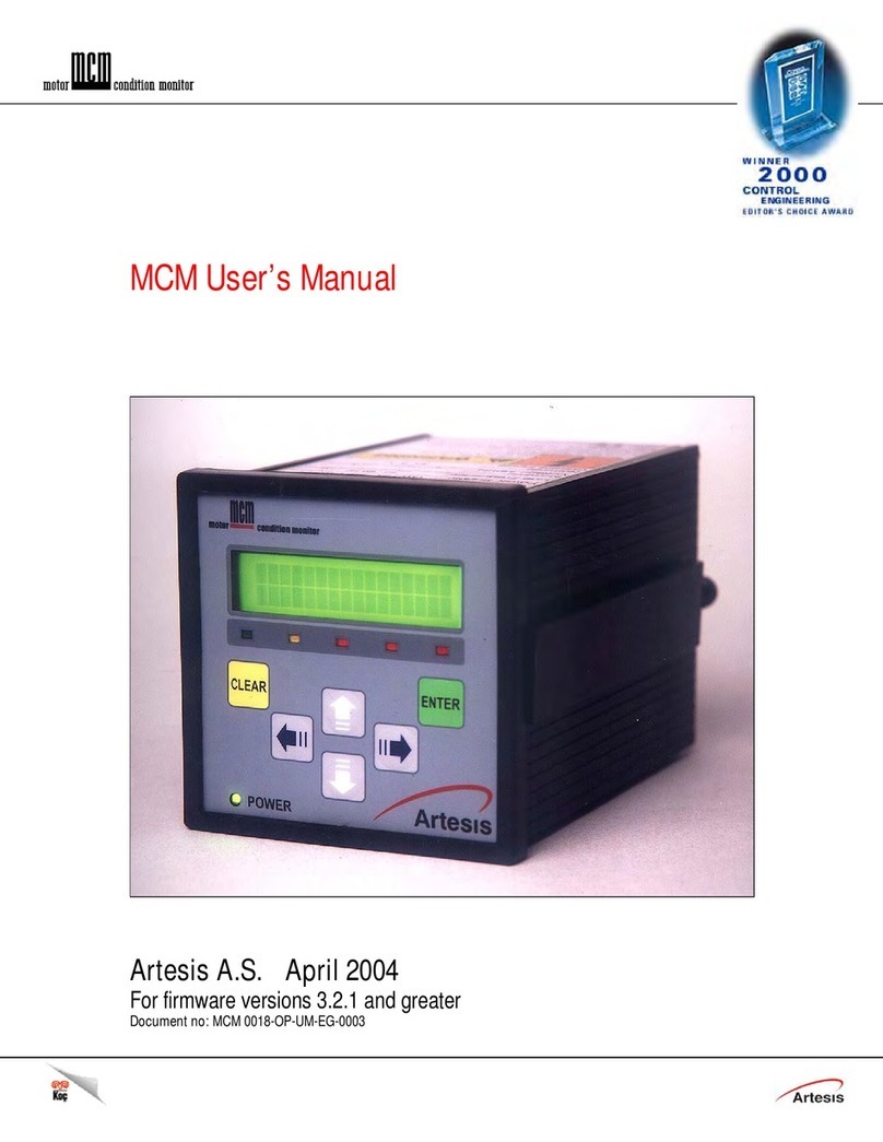
Artesis eMCM User manual

User Manual
Artesis Motor Condition Monitoring Systems
eMCM (Motor Condition Monitoring with Energy Meter)
PS.01 KL.25 REV:00

2
INDEX
Introduction........................................................................................................................................3
1. Overview ....................................................................................................................................3
2. Features ......................................................................................................................................3
3. Specification................................................................................................................................ 4
Installation ..........................................................................................................................................6
1. Installation ..................................................................................................................................6
2. Name...........................................................................................................................................7
3. Components..............................................................................................................................17
4. HMI ...........................................................................................................................................18
eMCM Using .....................................................................................................................................26
1. Communication Setup ..............................................................................................................26
2. First Use ....................................................................................................................................28
3. Diagnostic Function ..................................................................................................................39
Appendices .......................................................................................................................................49
1. Appendix 1: MCM Error, alarm and warning conditions..........................................................49
2. Appendix 2: Current and voltage sensor selection...................................................................52
3. Appendix 3: Connection Diagrams............................................................................................52
4. Appendix 4: HMI Menu settings and parameters.....................................................................55
5. Appendix 5: Flowcharts for Alarm Conditions.........................................................................56

3
Introduction
1. Overview
eMCM is
the
device
that
combines
current/voltage
signal a
na
l
y
si
s
technique
and
motor protection
technique. It
performs
motor protection
and diagnosis at
the
same
t
i
m
e
.
eMCM
ge
t
s
the
current/voltage
s
i
g
n
a
l
from
the motor
and processes
it
(spectrum analysis) so
that it operates as
motor
protection relay
as
well
as
motor
condition monitoring system which a
n
a
l
y
z
e
/
d
i
a
g
n
o
s
e
/
m
a
n
a
g
e
the
status of motor and
motor
l
oa
d.
While existing motor protection relay just detects current status
of
the
m
o
t
o
r
,
eMCM
,
in
addition,
can
predict
and
monitor motor condition
so
that it
ensures the motor safety
and stable
motor management.
eMCM performs motor
condition monitoring
based on
the technology
developed in NASA and
it
needs minimum user intervention. Furthermore, eMCM provides energy
consumption measuring, which enables user
to
come up
w
i
t
h
an effective
plan
for dealing
with
efficient energy
consumption.
eMCM is
t
he
convergence device which is
able to deal with protection,
condition monitoring
and energy measuring of
the motor
in one
devi
c
e
.
2. Features
•Provides condition monitoring and energy measuring of the motor in one device.
•Motor condition monitoring functions Watch Line, Watch Load, Electrical Faults, Mechanical
Faults
•Based on the technology developed in NASA
•Measuring functions voltage, current, power factor, frequency, power, power consumption,
unbalance, ground fault
•Provide RS-485 serial communication and Modbus ethernet communication
•External HMI module (2.7-inch LCD display)

4
3. Specification
Rated Specifications
General Information
Motor Type
3‐phase, AC motors & generator.
Motor current (load) variation must be less than 45%
during 6 sec data acquisition period. DOL, Star-Delta, Soft
Starter, Variable Frequency Driver
AMBIENT CONDITIONS
Operating Temperature
‐10 –50
⁰
C
Humidity
80%, Relative Humidity, non‐condensing
Pollution Degree
2
Altitude
2000m (6562ft)
IP Rating
IP40
INPUT SUPPLY VOLTAGE
Rated Voltage
100‐240 VAC / 120-370VDC
Allowable input voltage
90% ‐110% (of rated voltage)
Frequency
50/60Hz
Power Consumption
4W
Over Voltage Category
IEC61010 Cat III
MEASUREMENT VOLTAGE INPUTS
max 690Vac (Line to Line)
MEASUREMENT CURRENT INPUTS
Up to 2500A with three Cat III Current Transformers:
0.5% accuracy
FREQUENCY RANGE
15-120Hz
COMMUNICATION
Network
RS485 ‐Modbus‐RTU
TCP/IP ‐Modbus‐TCP
DISPLAY
4.3" LED
Displays electrical measurement, failure information, and
setting values
Status LEDs
Displays power status, module status, comm status,
alarm for diagnosis
PHYSICAL
Weight
1170 g (2.58 lb.)
Dimensions WxHxL
96 mm x 96 mm x 140 mm
Mounting
Front Panel Mounting (indoor)
COMPLIANCE & CERTIFICATIONS
EMC
EMC Directive 2004/108/EC, EN61326‐1, IEC61326‐1
Safety
Electrical Safety Directive 2006/95/EC,
EN61010‐1, IEC61010‐1
Measurement Functions
Voltage
3 phase voltage (line‐line), unbalance [%]
Current
3 phase current and leakage current, unbalance [%], THD [%]
Active Power
Measuring active power [kW]
Reactive Power
Measuring reactive power [kVAr]
Frequency
Measuring Frequency [Hz]
Power factor
Measuring Power factor
Energy
Total Whr, Today Whr, Prev day Whr
Data and Time
Year, month, day, hour, minute, second

5
Auxiliary Functions
Password
Password Secure configuration
Communication
serial/ethernet communication for monitoring status and event
history
Total Running‐Hour
Record of total running from installation which cannot be
modified or cleared
Alarm
output alarm signal to 3 output relays
Fault History
30(diagnosis) fault history to the flash memory
Limitation of auto reset attempt
Block auto‐reset if the reset count exceeds the pre‐set count
within 30 minutes
Date/Time Information Setting
Save date/time to provide exact time of motor failure
Motor Condition Monitor and Diagnostic Functions
Status
OK
Motor and driven system is working as expected.
Watch Line
Watch Line is usually temporary in nature and generally the
user does not need to take any action. However, it is
recommended that when this status level occurs, the user
should at least assess the extent of the change in the line
conditions, as significant changes in the line voltages and
currents may be dangerous to the motor. If the line status
change is persistent, the user should assess the root cause of
this change. For instance, it may be due to a problem in the
contactors or for inverter driven motors the settings of the
inverter may have been changed. In any case, if the root cause
cannot be remedied easily and quickly and the new voltage
supply condition presents no danger to the motor, the user
has the option to send MCM to the UPDATE mode. This will
allow MCM to learn the new voltage supply conditions, after
which the status will eventually return to normal.
Watch Load
If the process load has not been altered deliberately,
check for leakage, valve & vane adjustment, pressure
gauge faults, manometer, dirty filters (fans,
compressors). If the process is altered deliberately, device
should be updated.
Examine 1
Plan Maintenance (First Level Alarm): There are developing
mechanical and/or electrical fault(s). Although the level of the
failure is not serious, the maintenance should be done in next
planned stop or latest in 3 months.
Examine 2
Do Maintenance (Second Level Alarm): There are developing
mechanical and/or electrical fault(s). Maintenance and
corrective action should be performed as soon as possible.

6
Installation
1. Installation
Avoid
the
place
with
high
temperature
or high
electrical
f
i
e
l
d
.
In order
to
use
eMCM
cor
r
ect
l
y
,
following condition
should be
c
onsi
der
e
d.
Name
Description
Mounting
Indoor
Operating Temperature
-
10℃
~ 50
℃
Store Temperature
-
25℃
~ 70
℃
Humidity
Relative Humidity, 80%,
no
n-con
d
en
sing
eMCM should be installed within
the
cabinet panel or similar spaces in order
t
o
limit
user
access to
the terminal
contact. This is the
product
for an indoor and
it should not
be exposed to
the
external environment directly.

7
2. Name
No
Nam
e
Func
t
i
on
1
Supply
voltage terminal
Terminal for operational power
(
A
C100~2
40V)
2
Empty terminal
No Function
3
Motor
voltage
i
np
u
t
Terminal for motor
input
voltage
4
Status
LED
Indicates Power status, Module status, e
tc.
5
CT connection port
Terminal for 3 phase CT connection (RJ11)
6
ZCT connection port
Terminal for ground CT connection
7
Reset button
Trip Relay Reset Button
8
RS-485
terminal
Terminal for
RS-485
communication
9
HMI
t
erm
i
nal
Terminal for connecting with HMI (RJ45)
10
Empty terminal
No Function
11
Ethernet port
Terminal for ethernet communication (RJ45)

8
2.1 Supply Voltage Terminal
This is
the terminal to supply voltage to the
device.
(AC100~240V)
Pin
No
Description
N
Neutral
(
A
C)
L
Line
(
A
C)

9
2.2 Voltage Input Terminal
This is
the terminal
for measuring
motor input
v
o
l
t
a
g
e
.
Input voltage must be max. 690Vrms line
to line.
Pin
No
Description
L1
Connecting to R
p
hase
L2
Connecting to S
p
hase
L3
Connecting to T
p
hase

10
2.3 Status LED
Indicates device and
motor
condition monitoring status
No
LED Type
Desc
ription
1
Po
w
e
r
Indicating
power
status
of
the
d
e
v
i
c
e
2
StatusM
Indicating module diagnostic status
3
Empty
No Function
4
F
a
u
l
t
D
turned on when module find some changes during
motor condition monitoring
5
CommS
flashes when serial communication is in progress
6
CommE
flashes when ethernet communication is in progress

11
2.4 CT Connection Terminal
This is the terminal for connecting to external CT. eMCM uses dedicated CT
and
its pin number
is as
follows
.
✓CT wiring
should
be done
to
become 'K' of
the
CT
to direction
of power source and 'L'
to direction
of
the motor
l
oa
d
.
✓The K of
the
CT
terminal should
be
c
o
nn
e
c
t
e
d
with
K of
the
connector and L of
the
CT
terminal should
be connected with L of the connector.
✓The CT terminals max. current input are 100mA. Please, Use CTs recommended by Artesis.

12
2.5 RESET Button
Reset button can be used for two purpose.
1) When trip occurs, pressing this button resets relay immediately.
2) Pressing this button for more than 5 seconds makes setting value for protection function to
default one. This function will be useful when user forget password or IP address of the device.
Followings are the default parameters for protection function
Func
t
i
on
s
Default Val
u
e
IP Address
192.168.3.21
Gateway
Addre
ss
0
.0.0
.
0
Netmask
Addre
ss
0
.0.0
.
0
Password
0
Modbus
RS-485
Value
s
ID: 1, Speed: 9600bp
s
Modbus TCP
V
a
l
u
e
s
ID: 1,
Port:
502
Motor Frequency
50Hz
T
CC
Definite, class:
1
CT Ratio
1

13
2.6 RS-485 Terminal
eMCM operate as Modbus slave. External Modbus master device can acquire status data or
control
the
device through this port. Also, several eMCM can be connected through this port.
Pin No
Desc
ription
1
Transmit
+
2
Transmit
-
3
Ground
4
Frame Ground

14
2.7 HMI Port
eMCM can be connected with gems HMI through this port. User can monitor the status value
acquired from eMCM and change setting values.
Pin No
Desc
ription
3,
6
Signal Ground
4
T
r
a
n
s
m
i
t
5
R
eceive

15
2.8 Ethernet Port
AES Config and WEBHMI can acquire data from this port. User can change diagnosis settings or
acquire data from eMCM through this port.
RJ-45
Pin No
Description
1
Transmit
+
2
Transmit
-
3
Receive
+
6
Receive
-

16
2.9 Communication Connection Diagram

17
3. Components
3.1 eMCM & HMI

18
4. HMI
4.1 HMI
4.2 HMI Dimension
No
Name
Description
1
LCD Screen
4.3” TFT LCD
2
Status LED
Indication of operation status
3
Buttons
Six buttons are used to controlling HMI
4
Installation Clips
The clips are used for fixing the HMI to the panel
5
Comm Port
Communication output to eMCM
3
1
2
4
5

19
4.3 HMI Installation

20
4.4 HMI Menus
4.4.1 Main Screen
Parameter
Description
Voltage
Phase Voltage R-S
Current
Line Current R
Total Whr
Total power consumption
Frequency
Voltage Frequency
4.4.2 Status > Line Voltage
Parameter
Description
Vrs
Phase Voltage R-S
Vst
Phase Voltage S-T
Vtr
Phase Voltage T-R
Frequency
Voltage Frequency
Table of contents
Other Artesis Measuring Instrument manuals