Esam E1200 User manual

MANUALE D’USO / USER’S GUIDE
E1200
page 1 - 16
rev. 1.07
0714
ANALIZZATORE DI RETE
DI PRECISIONE
E1200
HIGH ACCURACY
NETWORK ANALYZER
L’analizzatore di rete E1200, interamente progettato e sviluppato da
ESAM, è costruito per soddisfare tutte le moderne esigenze di
misura e controllo dei parametri elettrici di una rete trifase.
Basato su un microprocessore di ultima generazione e dotato di un
circuito di misura con cambio portata automatico, ha un’elevata
precisione di misura ed è pertanto particolarmente adatto per
impieghi in laboratori e sistemi di acquisizione e di regolazione.
In aggiunta a tutte le misure del modello E1100, il modello E1200
calcola l’energia e la potenza media e dispone inoltre di 2 interfacce
seriali RS485 veloci e di un’interfaccia Ethernet per rete LAN.
La seconda interfaccia seriale può essere utilizzata ad esempio per
collegare un pannello operatore locale oppure per pilotare fino a 12
canali di output analogico tramite moduli Esam E3000, mentre la
prima resta disponibile per l’acquisizione dei dati.
L’interfaccia Ethernet consente la configurazione dell’ E1200 da
browser web e l’acquisizione delle misure via LAN con protocollo
Modbus/TCP.
L’accurato dimensionamento di ogni componente (es. circuiti
stampati omologati UL) e la taratura con strumenti certificati SIT
garantiscono la massima precisione ed affidabilità in ogni
condizione di utilizzo.
Le principali caratteristiche dell’analizzatore di rete E1200 sono le
seguenti:
elevata precisione di misura: 0.2% della lettura dal 5 al 100%
del campo di misura, frequenza AC da 45 a 65 Hz
elevate prestazioni con forme d’onda distorte: 256 campioni per
periodo di rete AC, banda passante di ingresso 2 kHz (-3dB)
multiportata automatico (7 campi di misura per tensioni e
correnti, G = 1,2,4,8,16,32,64)
calcolo ogni mezzo periodo di rete AC di tensioni di fase e
concatenate RMS, correnti di fase RMS e corrente di neutro
RMS, correnti e tensioni istantanee di picco, frequenza, potenze
attive, reattive e apparenti, fattore di potenza di ciascuna fase e
del sistema trifase
calcolo dell’energia attiva e reattiva, entrante e uscente, per
ciascuna fase (in presenza di neutro) e totale trifase
calcolo della potenza media degli ultimi 15 minuti, attiva e
reattiva, entrante e uscente, per ciascuna fase (in presenza
di neutro) e totale trifase
media valori letti programmabile da mezzo periodo di rete AC
(minimo) a 1 secondo (max)
analisi armonica di tensioni e correnti di fase, calcolo distorsione
armonica totale (THD)
rilevazione valori minimi e massimi di tutte le misure
2 interfacce seriali isolate RS485, 1200 … 115200 baud,
protocollo Modbus RTU slave, utilizzabili per la lettura delle
misure e la configurazione dello strumento. La seconda
interfaccia può essere in alternativa configurata come Modbus
master, per pilotare fino a 12 output analogici tramite moduli
ESAM E3000
interfaccia Ethernet: configurazione dello strumento e
visualizzazione misure da browser Web, acquisizione dati da
sistemi Scada con protocollo Modbus/TCP
inserzione trifase con 3 TA o 2 TA (ARON) o monofase con 1 TA
rapporti TA e TV configurabili
montaggio su profilato DIN EN50022-35
The Network analyzer E1200, entirely designed and developed by
ESAM, is built to comply with all the modern requirements of
measure and control of electrical parameters in a 3-phase network
Featuring a microprocessor of the latest generation and an
autoranging analog input stage, it has a high measuring accuracy
and is particularly suited for laboratory applications and
sophisticated data acquisition and control systems.
On top of alI the measurements provided by model E1100, model
E1200 calculates energy and average power; moreover it has 2 fast
RS485 serial interfaces and an Ethernet LAN interface.
The second serial interface can be used to connect a local operator
panel or to drive up to 12 analog outputs using Esam E3000
modules, while keeping the main data acquisition on the other serial
interface.
By means of the Ethernet interface the analyzer E1200 can be
configured with a Web browser and data acquisition can be
performed with Modbus/TCP protocol over a LAN.
The careful choice of every component (e.g. UL recognized printed
circuits) and the calibration with EAL.SIT certificated devices,
provide the highest precision and reliability in every condition of use.
The main features of the network analyzer E1200 are the following:
high accuracy: 0.2% of reading, from 5% to 100% of measuring
range, AC frequency 45 to 65 Hz
high accuracy with distorted waveforms: 256 samples every AC
period, 2kHz analog input bandwidth (-3bB)
autorange (7 ranges for input voltages and currents, G =
1,2,4,8,16,32,64)
calculation every half AC period of phase and linked RMS
voltages, phase RMS currents and neutral RMS current,
instantaneous peak voltages and currents, frequency, active,
reactive and apparent powers, power factor of each phase and
of 3-phase system
calculation of active and reactive energy, incoming and
outgoing, total and for each phase (when neutral is present)
calculation of average power over the last 15 minutes, active
and reactive, incoming and outgoing, total and for each
phase (when neutral is present)
averaging of measured values programmable from half AC
period (min) to 1 second (max)
Harmonic analysis of phase voltages and currents, calculation of
total harmonic distortion (THD)
Min and max values of every reading
2 RS485 insulated serial interface, 1200 ... 115200 baud,
Modbus RTU slave, which can be used to read measured values
and to preset instrument parameters. The second interface can
also be configured as Modbus master to drive up to 12 analog
outputs by means of ESAM E3000 modules.
Ethernet interface: the instrument can be configured and its
readings displayed with a Web browser, data acquisition
can be performed from a Scada system with Modbus/TCP
protocol
3-phase connection with 3 CT or 2 CT (ARON) or single-phase
with 1 CT
configurable CT and VT ratios
rail DIN EN50022-35 mounting
MANUALE D’USO / USER’S GUIDE
E1200
page 2 - 16
rev. 1.07
0714
Grandezze misurate / Measured Variables
Unità/Units
Tensioni di fase / Phase Voltages
V1N V2N V3N
[V]
Tensioni concatenate / Linked Voltages
V12 V23 V31
[V]
Tensioni istantanee di picco / Instantaneous peak voltages
V1pk V2pk V3pk
[V]
Tensione concatenata media / Linked average Voltage
Vtm
[V]
Correnti / Currents
I1 I2 I3
[A]
Correnti istantanee di picco / Instantaneous peak currents
I1pk I2pk I3pk
[A]
Corrente di neutro / Neutral current
Ineu
[A]
Corrente media / Average current
Itm
[A]
Distorsione armonica / Total harmonic distortion
Thd V1-V2-V3 Thd I1-I2-I3
[%]
Potenza attiva totale e di fase / Total and Phase Active Power
Ptot P1 P2 P3
[W]
Potenza reattiva totale e di fase / Total and Phase Reactive Power
Qtot Q1 Q2 Q3
[VAR]
Potenza apparente totale e di fase / Total and Phase Apparent Power
Stot S1 S2 S3
[VA]
Fattore di potenza totale e di fase / Total and Phase Power Factor
PF PF1 PF2 PF3
Frequenza / Frequency
Frequency
[Hz]
Energia attiva entrante / Active Energy In
Ea+Ea1+ Ea2+ Ea3+
[Wh]
Energia attiva uscente / Active Energy Out
Ea- Ea1- Ea2- Ea3-
[Wh]
Energia reattiva entrante / Reactive Energy In
Er+Er1+ Er2+ Er3+
[VARh]
Energia reattiva uscente / Reactive Energy Out
Er-Er1- Er2- Er3-
[VARh]
Potenza attiva media entrante (ultimi 15 minuti) / Average Active Power In (last 15 minutes)
Pm+ Pm1+ Pm2+Pm3+
[W]
Potenza attiva media uscente (ultimi 15 minuti) / Average Active Power Out (last 15 minutes)
Pm- Pm1-Pm2-Pm3-
[W]
Potenza reattiva media entrante (ultimi 15 minuti) / Average Reactive Power In (last 15 minutes)
Qm+ Qm1+ Qm2+Qm3+
[VAR]
Potenza reattiva media uscente (ultimi 15 minuti) / Average Reactive Power Out (last 15 minutes)
Qm- Qm1- Qm2- Qm3-
[VAR]
Ampiezza armoniche / Amplitude of harmonics ( V1, I1, V2, I2, V3, I3)
[%]
Valori massimi e minimi di tutte le misure / Min and Max values of every reading
[…]min […]max
[…]
Senso ciclico delle fasi / Phase sequence
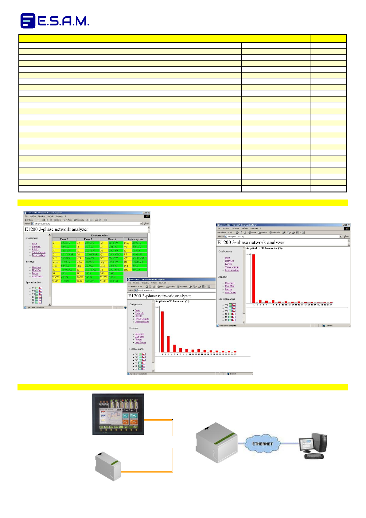
Esempi di pagine tratte dal WEB SERVER integrato
Ex. of pages from embedded WEB SERVER
Esempio di collegamento interfacce Seriali - Ethernet
Ex. of Serial Interfaces - Ethernet connection
RS485 - 1
interfaccia Seriale N° 1
collegata a Modbus Master
Serial Interface No. 1
connect to Modbus Master
RS485 -1
E1200
Modbus TCP/IP
RS485 -2
RS485 - 2
Interfaccia Seriale N° 2
collegata a Modbus Slave
(es. E3000) / Serial Interface
No. 2 connect to Modbus
Slave (e.g. E3000)
MANUALE D’USO / USER’S GUIDE
E1200
page 3 - 16
rev. 1.07
0714
DATI TECNICI
TECHNICAL DATA
tensione nominale Vn: 230V fase/neutro, 400V fase/fase
campo di misura tensione: 0 … 1.2 Vn
corrente nominale d’ingresso In: 5A
campo di misura corrente: 0 … 1.2 In
sovraccarico permanente: 1.5Vn, 2In
sovraccarico istantaneo (1 sec.): 2Vn, 20 In
rapporto TA esterno impostabile: 1 … 99999
rapporto TV esterno impostabile: 1 … 99999
tempo di media valori misurati: ½ periodo AC … 1 sec
classe di precisione per tensioni, correnti e potenza attiva: ±
0,2% della lettura (5 ... 100% del campo di misura, 45 … 65 Hz)
coefficiente di temperatura: ±0,01%/°C
interfaccia seriale RS485: 1200 … 115200 baud, Modbus RTU
acquisizione dati veloce: tipico 40 variabili in circa 40 msec
interfaccia Ethernet: 10 Mbit/s, connettore RJ45, protocolli HTTP
(web server integrato) e Modbus/TCP (per acquisizione dati, max
3 connessioni simultanee)
alimentazione ausiliaria in corrente alternata: 115-230V 50/60Hz
oppure in opzione: 24V o 100V o 400V ±15% - consumo 4VA
alimentazione ausiliaria opzionale in corrente continua:
12V oppure 24V oppure 48V oppure 110V oppure 220V ± 10%
(Morsetti : [V0] -e [V2] +) - consumo: 4W
conforme a EN61010-1 Cat.Inst.II (sicurezza) e EN61326 (EMC)
isolamento fra ingressi V e ingressi I: 4kV (60sec,50Hz)
isolamento fra due ingressi I: 4kV (60sec,50Hz)
isolamento fra ingressi e altri morsetti: 4kV (60sec,50Hz)
isolamento fra uscite e alim. ausiliaria: 2kV (60sec,50Hz)
isolamento fra due uscite: 1kV (60sec,50Hz)
temperatura di funzionamento -10° … +55°C
temperatura di impiego +5° … +40°C
temperatura di immagazzinamento -30° … +70°C
temperatura di riferimento +20°C
nominal voltage Vn: 230V phase/neutral, 400V phase/phase
input voltage range: 0 ... 1.2Vn
nominal input current : 5A
input current range: 0 … 1.2 In
continuous overload: 1.5Vn, 2In
instantaneous overload (1 sec): 2Vn, 20In
programmable external TV ratio: 1 ... 99999
programmable external TV ratio: 1 ... 99999
averaging time interval: ½ AC period ... 1 sec
accuracy (voltage, current, active power): ± 0,2% of reading
(5 ... 100% of input range, 45 … 65 Hz)
temperature coefficient: ±0,01%/°C
RS485 serial interface: 1200 ... 115200 baud, Modbus RTU
fast data acquisition: typically 40 variables in about 40 msec
Ethernet interface: 10 Mbit/s, RJ45 connector, HTTP protocol
(embedded web server) and Modbus/TCP (for data acquisition,
max 3 simultaneous connections)
a.c. auxiliary power: 115-230V 50/60Hz or in option:
24Vac or 100Vac or 400Vac ± 15% - consumption:
4VA
optional d.c. auxiliary power: 12Vdc or 24Vdc or 48Vdc or
110Vdc or 220Vdc ± 10% (input terminals: [V0] -and [V2] +)
consumption:
4W
complies with EN61010-1 Inst.cat.II (safety) and EN61326 (EMC)
Insulation V inputs to I inputs: 4kV (60sec,50Hz)
Insulation between two I inputs: 4kV / 60sec, 50Hz
Insulation, inputs to any other terminal: 4kV (60sec 50Hz)
Insulation outputs to aux.power: 2kV (60sec,50Hz)
Insulation between two outputs: 1kV (60sec,50Hz)
operating temperature range -10° … +55°C
calibrated temperature range +5° … +40°C
storage temperature range -30° … +70°C
reference temperature +20°C
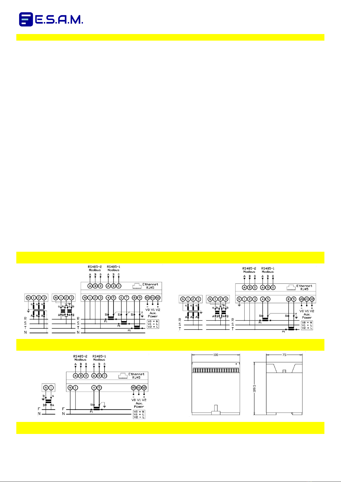
SCHEMI D’INSERZIONE - DIMENSIONI D’INGOMBRO / WIRING DIAGRAMS - OVERALL DIMENSIONS
Circuito trifase a 4 fili (3 TA)
Three-phase 4 wires circuit (3 CT)
Circuito trifase a 3 fili (2 TA, inserzione ARON)
Three-phase 3 wires circuit (2 CT, ARON insertion)
Circuito monofase
Single-phase circuit
Dimensioni d’ingombro
Overall dimensions
montaggio su profilato DIN EN50022-35 / rail DIN EN50022-35 mounting
Circuito trifase a 4 fili (3 TA)
Three-phase 4 wires circuit (3 CT)
Circuito trifase a 3 fili (2 TA, inserzione ARON)
Three-phase 3 wires circuit (2 CT, ARON insertion)

MANUALE D’USO / USER’S GUIDE
E1200
page 4 - 16
rev. 1.07
0714
ISTRUZIONI DI INSTALLAZIONE / INSTALLATION INSTRUCTIONS
Sull’apparecchio e nella documentazione sono utilizzati i
seguenti simboli:
Attenzione: consultare la documentazione del prodotto
Attenzione: rischio di scossa elettrica
Conformità del prodotto alle direttive CE applicabili
Conformità del prodotto alla direttiva 2002/96/EC sui rifiuti
elettrici ed elettronici
L’installazione può comportare l’esposizione a tensioni
pericolose e pertanto deve essere eseguita solo da personale
qualificato, nel rispetto delle norme sulla sicurezza elettrica: in
caso di dubbi, consultare la persona responsabile per la
realizzazione o la manutenzione dell’impianto.
L'apparecchio è previsto per montaggio su guida DIN all'interno
di quadri elettrici che garantiscano adeguata protezione
ambientale.
L'ingresso di alimentazione ausiliaria deve essere collegato a un
interruttore / disgiuntore situato in prossimità dell'apparecchio e
facilmente accessibile all'operatore
ll fabbricante non si assume alcuna responsabilità per
installazione non eseguita correttamente.
Se l’apparecchio viene usato in un modo non specificato dal
fabbricante, la protezione fornita dall’apparecchio può essere
compromessa.
The following symbols are used on the equipment and in the
product documentation:
Caution: refer to product documentation
Caution: risk of electric shock
Compliance of the product with European CE directives
Compliance of the product with directive 2002/96/EC
about electrical and electronic waste
Installation may imply exposure to dangerous voltages, so must
be handled by qualified personnel only, in conformity with
electrical safety regulations: in case of any doubt, contact the
person responsible for the plant installation / maintenance.
The equipment is designed for DIN rail mount inside electrical
switchgears, which must provide adequate environmental
protection.
The auxiliary power supply input must be connected to a switch
or circuit breaker, located in close proximity to the equipment
and within easy reach of the operator
The manufacturer does not take any responsibility for improper
installation.
If the equipment is used in a manner not specified by the
manufacturer, the protection provided by the equipment may be
impaired.
INTERFACCIA ETHERNET / ETHERNET INTERFACE
CONFIGURAZIONE RETE / NETWORK CONFIGURATION
L’E1200 è dotato di un’interfaccia di rete Ethernet a 10 Mbit/s: in
reti miste 10/100/1000 Mbit/s ciò non costituisce un problema
purché l’E1200 venga collegato a uno switch di rete. Evitare
invece di usare uno hub, in quanto ciò rallenterebbe anche i
dispositivi in grado di comunicare fra di loro a velocità maggiore.
Lo strumento è dotato di un connettore di rete standard RJ45 e
ha la seguente configurazione di default:
Indirizzo IP: 192.168.0.250
Netmask: 255.255.255.0
Gateway (IP del router): 192.168.0.200
Porta web server: 80
Porta Modbus/TCP: 502
E1200 has a 10 Mbit/s Ethernet interface: it works fine with
higher speed devices (100/1000 Mbit/s), as far as it is connected
to the network via a network switch. Don’t use a hub instead,
because in that case also higher speed network nodes would be
slowed down.
The instrument is fitted with a standard RJ45 network connector
and has the following default network configuration:
IP address: 192.168.0.250
Netmask: 255.255.255.0
Gateway (router IP): 192.168.0.200
Web server port: 80
Modbus/TCP port: 502
WEB SERVER INTEGRATO / EMBEDDED WEB SERVER
Su uno strumento nuovo, impostare i parametri di connessione
nel modo seguente:
Connettere lo strumento a un PC con un cavo di rete
incrociato
Nella configurazione di rete del PC (come accedervi dipende
dal sistema operativo del PC) impostare parametri TCP/IP
compatibili con quelli di default dell’E1200 (es. indirizzo IP
del PC 192.168.0.1, netmask 255.255.255.0)
Aprire un browser e digitare http://192.168.0.250: apparirà la
home page del web server integrato. Se lo strumento non è
nuovo o comunque i suoi parametri di connessione non
fossero noti, premere per alcuni secondi il pulsante
“RESET” che ripristina le impostazioni di fabbrica di tutti i
canali di comunicazione (porte seriali, web server e server
Modbus/TCP) e riprovare la procedura sopra descritta.
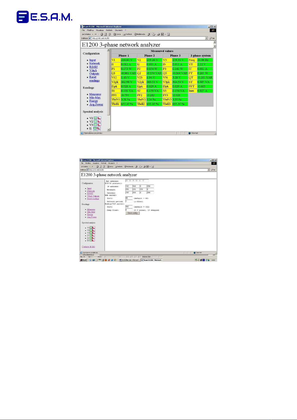
La schermata iniziale del web server integrato ha il seguente
aspetto:
On a new instrument, set the connection parameters as follows:
Connect the instrument to a PC using a crossover network
cable
Enter PC network configuration (how to do this depends on
your PC operating system) and set TCP/IP parameters
compatible with the default E1200 configuration (e.g.: PC
IP address 192.168.0.1, netmask 255.255.255.0)
Open a browser and enter http://192.168.0.250: you will get
the home page of the embedded web server, If your E1200
is not new or its network settings are unknown, press for a
few seconds the “RESET” button to restore to factory
default settings for all communication interfaces (serial
ports, web server, Modbus/TCP server). Then retry the
above described procedure.
The home page of the embedded web server looks like
this:
MANUALE D’USO / USER’S GUIDE
E1200
page 5 - 16
rev. 1.07
0714
Dopo aver visualizzato la home page del web server integrato,
fare click su “Network”, quindi impostare valori dei parametri di
connessione compatibili con quelli della propria rete locale.
When you have got the home page of the embedded web
server, click on “Network”, then enter settings of your choice,
compatible with your LAN.
L’analizzatore di rete E1200 non supporta il DHCP e richiede
pertanto l’assegnazione manuale di un indirizzo IP compatibile
con quelli della rete: tale indirizzo deve essere diverso dagli IP
statici già esistenti nella rete locale e fuori dal campo di quelli
dinamici gestiti dal router di rete con il protocollo DHCP.
L’impostazione del gateway (indirizzo IP del router) serve se si
vuole accedere all’E1200 dall’esterno della rete locale:
ovviamente in tal caso sarà necessario configurare anche il
router in modo appropriato.
Può essere necessario modificare la porta usata dal web server
(default=80) solo in casi molto particolari, ad esempio quando
sulla rete locale vi siano due web server e si voglia poterli
raggiungere entrambi dall’esterno.
Premere infine “Save Config”: lo strumento inizierà ad utilizzare i
nuovi parametri di connessione e pertanto in generale non sarà
più possibile visualizzare le pagine del web server dal PC.
Sconnettere ora il cavo di rete incrociato e ripristinare sul PC le
originarie impostazioni TCP/IP.
Collegare l’E1200 a uno switch di rete con un cavo normale: se
l’E1200 è stato correttamente configurato a questo punto sarà
accessibile con un browser da qualsiasi PC collegato alla rete.
Lo strumento è completamente configurabile per mezzo del web
server. Il web server consente inoltre la visualizzazione di tutti i
valori misurati e calcolati.
The E1200 network analyzer does not support DHCP and
therefore requires the manual assignment of an IP address: this
address must be different from any static IP address already
assigned in the local network and out of the range of dynamic IP
addresses managed by the router using DHCP.
The gateway address (router IP address) is required to allow
access to the E1200 from outside the LAN: of course in that
case also the router has to be properly configurated.
There is normally no need to change the web server port
(default=80): a different choice is required only in special cases,
e.g. when there are two web servers on the LAN and both must
be accessible from outside.
After all settings have been made, press “Save Config”: the
instrument will start using the new network configuration and
therefore in most cases its web server will be no longer visible
from the PC.
Disconnect now the crossover cable, restore the original TCP/IP
configuration on the PC and connect the E1200 to a network
switch with a standard patch cable: if the E1200 has been
properly configurated, its web server will be visible with a
browser from any PC connected to the LAN.
The instrument can be fully configured using the web server.
Moreover the web server can be used for visual monitoring of all
the measured and calculated values.

MANUALE D’USO / USER’S GUIDE
E1200
page 6 - 16
rev. 1.07
0714
Il menù “Configuration” consente di impostare:
-Input
rapporto TV
rapporto TA
inserzione trifase RSTN / Aron
tempo di risposta
unità di misura energia
intervallo di tempo per calcolo potenze medie
-Network
Indirizzo IP
Netmask
Indirizzo Gateway (indirizzo IP del router lato LAN)
Porta Modbus/TCP
Opzione scambio word dei numeri in formato float
Porta web server
Tempo di refresh delle misure sul web server
The configuration menu allows the following settings:
-Input
VT ratio
CT ratio
3-phase connection RSTN / Aron
response time
energy units
time interval for average power calculation
-
-Network
IP address
Netmask
Gateway address (router IP address, LAN side)
Modbus/TCP port
Option to swap words of floating point numbers
Web server port
Web server readings refresh time
-RS485
Per ciascuna porta seriale:
Baud rate
Slave address
Minimo ritardo alla risposta
Opzione scambio word dei numeri in formato float
Solo per la porta seriale 2:
Modbus master / slave: la modalità modbus master è
specificamente implementata per il pilotaggio dei moduli
di output analogico E3000
-V/mA Outputs
Per ogni uscita analogica con moduli E3000 (max 4 moduli
E3000 = 12 uscite analogiche):
Tipo di output (0-10V, 4-20mA, …)
Uscita normale / invertita (es. 4-20 o 20-4 mA)
Funzione di uscita nel caso del fattore di potenza
Inizio campo della variabile in uscita
Fine campo della variabile in uscita
-Reset readings
Distinti comandi consentono l’azzeramento di:
Massime potenze medie
Massimi e minimi delle misure
Valori delle energie
-RS485
For each serial port:
Baud rate
Slave address
Minimum delay before reply
Option to swap words of floating point numbers
Only for serial port 2:
Modbus master / slave: modbus master mode is
specifically implemented to drive E3000 analog output
modules
-V/mA Outputs
For each E3000 analog output (max 4 E3000 modules = 12
analog outputs):
Output type (0-10V, 4-20mA, …)
Normal / inverted output (e.g 4-20 or 20-4 mA)
Output function for power factor readings
Low range of output variable
High range of output variable
-Reset readings
Individual commands allow to reset:
Max average power values
Min / max values of all the readings
Energy values
SERVER MODBUS/TCP / MODBUS/TCP SERVER
Il protocollo Modbus/TCP è supportato dalla maggior parte dei
programmi di supervisione e acquisizione dati.
Esso permette la trasmissione di messaggi Modbus all’interno di
pacchetti TCP: a tale scopo il protocollo inserisce all’inizio di
ogni messaggio Modbus tre campi aggiuntivi, di 2 bytes
ciascuno:
Transaction identifier: numero arbitrariamente assegnato
dal client Modbus/TCP, ritornato dal server insieme alla
risposta, per identificare a quale domanda si riferisce
Protocol identifier: deve essere = 0 per identificare
Modbus/TCP
Length: lunghezza in bytes di ciò che segue, ovvero del
messaggio Modbus privato del CRC. Il CRC viene omesso
in quanto gli errori di trasmissione sono già gestiti dal TCP
The Modbus/TCP protocol is supported by most software
packages for data acquisition, monitoring and control.
It works loading Modbus messages inside TCP packets and
transferring them over a TCP/IP network. For this purpose three
additional fields, 2 bytes each, are sent before any Modbus
message, namely:
Transaction identifier: arbitrary number assigned by the
Modbus/TCP client, sent back by the server with the reply,
so that the client can match the reply with the
corresponding query
Protocol identifier: must be = 0 to identify Modbus/TCP
Length: number of following bytes, that is Modbus
message without CRC. The CRC is omitted because
transmission errors are already managed by TCP.
Ordinario messaggio Modbus:
Standard Modbus message:
Slave address
Function code
Data
CRC
Messaggio Modbus/TCP:
Modbus/TCP message:
Transaction identifier
Protocol identifier
Length
Slave address
Function code
Data

MANUALE D’USO / USER’S GUIDE
E1200
page 7 - 16
rev. 1.07
0714
Il protocollo Modbus/TCP usa di default la porta 502: è possibile
tuttavia impostare una porta diversa nella pagina “Network “ del
web server integrato.
E’ possibile inoltre scegliere l’ordine di trasmissione delle due
word di un valore floating point, vedi per i dettagli protocollo
Modbus, nota 2.
Una connessione Modbus/TCP, una volta aperta, può
trasportare tutto l’ordinario traffico di una rete Modbus ed è
quindi possibile, in linea di principio, utilizzarla per interfacciare
255 dispositivi diversi; nel caso specifico è al servizio di un solo
E1200, a cui deve essere assegnato slave address 1.
Il server Modbus/TCP dell’ E1200 supporta fino a 3 connessioni
simultanee, è cioè possibile leggere le misure dell’E1200
contemporaneamente da 3 client Modbus/TCP, oltre che dalle
due porte seriali RS485 e dal Web server.
The default port number assigned to the Modbus/TCP protocol
is 502: if desired you can select a different port in the “Network”
page of the embedded web server.
Moreover it is possible to choose the order of transmission of
the two words of a floating point number, for details see Modbus
protocol, note 2.
A Modbus/TCP connection, once opened, can carry all the
ordinary traffic of a Modbus network and can be used, in
principle, to interface up to 255 slave Modbus nodes; in our
case it is used for a single E1200 device, which must be
assigned slave address 1
The E1200 Modbus/TCP server supports up to 3 simultaneous
connections, that is the measured values can be read from 3
Modbus/TCP clients at the same time, other than from the 2
serial ports and the web server.
INTERFACCE SERIALI / SERIAL INTERFACES
Sono disponibili due porte seriali RS485: entrambe usano 1 start
bit, 8 bit di dati, nessun bit di parità, 1 stop bit: questa è una
impostazione predefinita, che non può essere modificata.
I parametri configurabili per ciascuna porta seriale sono:
BAUD: velocità di comunicazione, valori selezionabili 1200,
2400, 4800, 9600, 19200, 38400, 57600, 115200 baud
NUMT: numero terminale, valori validi 1 .. 255
XDEL: minimo intervallo di tempo fra la ricezione di un
comando Modbus e la trasmissione della risposta da
parte dell’E1200. Impostare questo parametro in modo
che il convertitore RS232/485, se presente, e l’unità
Modbus master (PLC, PC) siano entrambi pronti a
ricevere quando l’E1200 inizia a rispondere
SWFP: ordine di trasmissione delle due word dei valori floating
point, valori validi 0-1, vedi protocollo Modbus, nota 2
Parametro configurabile solo per la seconda porta seriale:
PROT: selezione Modbus slave (PROT=2, default), oppure
Modbus master (PROT=4), per pilotaggio moduli di
output analogico E3000
Impostazioni default di fabbrica per entrambe le porte:
NUMT = 1, BAUD = 9600, XDEL = 5 ms, SWFP = 0.
Per la seconda porta: PROT = 2
Il modo più semplice per configurare le porte seriali è quello di
utilizzare il web server dell’E1200. Se la connessione di rete non
è disponibile si può usare una porta per configurare l’altra.
Se le impostazioni delle porte seriali non sono note, premere per
alcuni secondi il pulsante “RESET” che ripristina le impostazioni
di fabbrica di porte seriali, web server e server Modbus/TCP.
Two RS485 serial ports are available: both ports use 1 start bit,
8 data bits, no parity, 1 stop bit: this is a predefined setting
that cannot be changed.
For each serial port the following parameters can be set:
BAUD: communication speed, selectable values 1200, 2400,
4800, 9600, 19200, 38400, 57600, 115200 baud
NUMT: slave address, valid values 1 .. 255
XDEL: minimum time interval between the reception of a
Modbus command and the transmission of the reply by
E1200. Set this parameter so that the RS232/485
converter, if present, and the Modbus master unit (PLC,
PC) are both ready to receive when E1200 starts
transmitting.
SWFP: Option to swap words of floating point numbers, valid
values 0-1, see Modbus protocol, note 2
Additional parameter available only for serial port 2:
PROT: selection between Modbus slave (PROT=2, default), or
Modbus master (PROT=4), to drive E3000 analog
output modules
Default factory settings for both serial ports:
NUMT = 1, BAUD = 9600, XDEL = 5 ms, SWFP = 0.
For second port only: PROT = 2
The easiest way to configure the serial ports is by means of the
E1200 web server. If no network connection is available, one
serial port can be used to configure the other one.
If the serial port settings are unknown, press for a few seconds
the “RESET” button to restore the default factory settings of
serial ports, web server and Modbus/TCP server.
INSERZIONI CORRETTE / CORRECT INSERTIONS
INSERZIONE ERRATA / WRONG INSERTION
Nota:
Il collegamento indicato con 0è da effettuare solo con SLAVE isolati
(Come tutti gli strumenti ESAM con seriale RS485 e protocollo Modbus RTU)
Note:
The connection marked with 0
is possible only with insulated SLAVES
(As all ESAM meters with serial RS485 and Modbus RTU protocol )

MANUALE D’USO / USER’S GUIDE
E1200
page 8 - 16
rev. 1.07
0714
PROTOCOLLO MODBUS RTU / MODBUS RTU PROTOCOL
Funzioni Modbus RTU implementate:
- 03 read holding registers. E’ possibile leggere fino a 120 word
per volta. Entrambe le word dei valori valori floating point devono
essere lette con una singola richiesta.
Se l’indirizzo iniziale o finale cade in mezzo ad un valore floating
point verrà ritornato un codice di errore (illegal address).
- 06 preset single register. Questo comando funziona solo con
valori interi. I valori floating point devono essere scritti con “preset
multiple register”
- 16 preset multiple register. Questo comando è utilizzato per
scrivere un valore floating point (2 word). E’ utilizzabile anche per
scrivere un valore intero (1 word)
Si può scrivere un solo valore intero o floating point alla volta.
Modbus RTU functions implemented:
- 03 read holding registers. Up to 120 words of contiguous data
can be retrieved at a time. Both words of floating point values must
be read with a single query. The instrument sends back an exception
response (illegal address) if the initial and final register of the query
are not chosen properly
- 06 preset single register. This command works only with integer
values. Floating point values must be written with “preset multiple
registers”
- 16 preset multiple register. This command is intended to write a
floating point value (2 words). Can be used also to write an integer
value (1 word).
Only a single value at a time can be written (float or integer).
Tipi di dati. La comunicazione seriale avviene tramite la
trasmissione di parole binarie di 16 bit (word). I dati sono di due tipi:
interi (una word) e floating point (2 word).
Esempio: Per leggere quattro misure partendo dal registro 100. si
dovranno chiedere 8 word, quindi i registri da 100 a 107.
Valori floating point. I numeri floating point seguono la specifica
IEEE 32 bit floating point standard.
Data types. Serial communication basically consists of 16 bit binary
words. Two data types are used: integer (one word) and floating
point (2 words).
Example: To read 4 measured values starting register 100,
8 words are required, that is from register 100 to 107.
Floating point value. According to the IEEE 32 bit standard format,
a floating point value is coded as follows:
MSB
LSB
seeeeeee : emmmmmmm
:
mmmmmmmm : mmmmmmmm
word A
word B
ssegno del numero 0 positivo 1 negativo
eesponente a 8 bit
mmantissa del numero 23 bit
Comando SWFP: Impostando 0 si riceverà prima la word A e poi la
word B; impostando 1 prima la word B e poi la word A
Codici di errore Modbus RTU implementati:
-1 illegal function - funzione non valida o non implementata.
-2 illegal data address - richiesta di lettura o scrittura ad un
indirizzo non valido. Es. registro inesistente, lettura di una sola
word di un valore float.
-3 illegal data value - scrittura di un valore non valido, ad esempio
fuori dai limiti ammessi.
s Sign bit. ”0” if the value is positive, “1” if the value is negative
e 8 bit exponent
m The mantissa, which is coded in 23 bits.
SWFP Command: Setting to 0 word A will be sent before word B;
setting 1 word B will be sent before word A.
Modbus RTU implemented exception codes:
-1 illegal function - invalid or non implemented function.
-2 illegal data address - read or write request at an invalid
address. Ex. Non existent register, read one word only of a
floating point value.
-3 illegal data value - write request of an invalid value, e.g. out of
allowed limits.
BLOCCO VIRTUALE DI REGISTRI MODBUS / VIRTUAL BLOCK OF MODBUS REGISTERS
La lettura di un blocco di registri modbus è molto più efficiente della
lettura separata di tante singole variabili, ma richiede che le variabili
occupino registri modbus consecutivi.
In questo strumento esiste la possibilità di creare un blocco virtuale,
che faccia apparire in sequenza variabili sparse.
La massima lunghezza del blocco virtuale è di 50 word.
Il blocco virtuale si trova nei registri modbus da 2100 a 2149.
La definizione delle variabili del blocco virtuale si trova nei registri
modbus da 2000 a 2049.
Esempio 1:
Scrivendo nei registri modbus da 2000 a 2005 i numeri 100, 0, 122,
0, 144, 0, ogni successiva richiesta di un blocco di 6 word a partire
dal registro 2100 ritornera' i valori di V1 (registri 100-101), V2
(registri 122-123) e V3 (reg. 144-145).
Notare che ogni valore di 32 bit (float) occupa 2 registri virtuali e che
deve essere inserito uno zero come secondo registro
Esempio 2:
Scrivendo nei registri modbus 2000 ... 2005 i numeri 500, 501, 304,
0, 502, 503, ogni successiva richiesta di un blocco di 6 word a partire
dal registro 2100 ritornera' i valori di indirizzo di stazione (registro
500), baud rate (registro 501), rapporto TA esterno (registri 304-305
), minimo ritardo alla risposta (registro 502) e swap float (registro
503). Notare che il rapporto TA (float) richiede 2 registri virtuali e che
e' stato inserito uno zero come secondo registro.
Reading a block of Modbus registers with a single query is much
more efficient than reading individual variables, but works only if the
variables are located in contiguous registers.
This instrument allows to define a “virtual block” of variables, that is
to read an arbitrary chosen list of variables as if their were
contiguous. The maximum length of the virtual block is 50 words.
The virtual block is located in registers from 2100 to 2149.
The list of variables of the virtual block is defined in registers from
2000 to 2049
Example 1:
Writing the numbers 100, 0, 122, 0, 144,0, to Modbus registers from
2000 to 2005, any following query of a block of 6 words, starting from
register 2100 will return the values of V1 (registers 100-101), V2
(registers 122-123) and V3 (registers 144-145).
Please note that every float requires two virtual registers and that a
zero must be entered as second register.
Example 2:
Writing the numbers 500, 501,304, 0, 502, 503, to Modbus registers
from 2000 to 2005, any following query of a block of 6 words, starting
from register 2100 will return the values of station address (register
500), baud rate (register 501),external CT ratio (registers 304-305),
minimum reply delay time (register 502) and swap float (register
503). Please note that CT ratio (float) requires two virtual registers
and that a zero must be entered as second word register.

MANUALE D’USO / USER’S GUIDE
E1200
page 9 - 16
rev. 1.07
0714
Tab. 1: REGISTRI DELLE MISURE / REGISTERS OF MEASURED VALUES
Register
Type
Read / Write
Label
Description
Aron
Unit
100-101
Float
Read only
V1
Tensione fase 1 / Voltage Phase 1
V
102-103
Float
Read only
I1
Corrente fase 1 / Current Phase 1
A
104-105
Float
Read only
P1
Potenza attiva fase 1 / Active power Phase 1
W
106-107
Float
Read only
Q1
Potenza reattiva fase 1 / Reactive power Phase 1
VAR
108-109
Float
Read only
V12
Tensione concatenata fase 1-2 / Linked Voltage Phase 1-2
V
110-111
Float
Read only
V1pk
Valore picco V1 nell’ultimo periodo AC / V1 peak value in last AC period
V
112-113
Float
Read only
IP1pk
Valore picco I1 nell’ultimo periodo AC / I1 peak value in last AC period
A
114-115
Float
Read only
S1
Potenza Apparente fase 1 / Apparent power Phase 1
VA
116-117
Float
Read only
PF1
Fattore di potenza fase 1 / Power factor Phase 1
118-119
Float
Read only
THD V1
Distorsione armonica totale V1 / Total harmonic distortion V1
%
120-121
Float
Read only
THD I1
Distorsione armonica totale I1 / Total harmonic distortion I1
%
122-123
Float
Read only
V2
Tensione fase 2 / Voltage Phase 2
V
124-125
Float
Read only
I2
Corrente fase 2 / Current Phase 2
A
126-127
Float
Read only
P2
Potenza attiva fase 2 / Active power Phase 2
W
128-129
Float
Read only
Q2
Potenza reattiva fase 2 / Reactive power Phase 2
VAR
130-131
Float
Read only
V23
Tensione concatenata fase 2-3 / Linked Voltage Phase 2-3
V
132-133
Float
Read only
V2pk
Valore picco V2 nell’ultimo periodo AC / V2 peak value in last AC period
V
134-135
Float
Read only
I2pk
Valore picco I2 nell’ultimo periodo AC / I2 peak value in last AC period
A
136-137
Float
Read only
S2
Potenza Apparente fase 2 / Apparent power Phase 2
VA
138-139
Float
Read only
PF2
Fattore di potenza fase 2 / Power factor Phase 2
140-141
Float
Read only
THD V2
Distorsione armonica totale V2 / Total harmonic distortion V2
%
142-143
Float
Read only
THD I2
Distorsione armonica totale I2 / Total harmonic distortion I2
%
144-145
Float
Read only
V3
Tensione fase 3 / Voltage Phase 3
V
146-147
Float
Read only
I3
Corrente fase 3 / Current Phase 3
A
148-149
Float
Read only
P3
Potenza attiva fase 3 / Active power Phase 3
W
150-151
Float
Read only
Q3
Potenza reattiva fase 3 / Reactive power Phase 3
VAR
152-153
Float
Read only
V31
Tensione concatenata fase 3-1 / Linked Voltage Phase 3-1
V
154-155
Float
Read only
V3pk
Valore picco V3 nell’ultimo periodo AC / V3 peak value in last AC period
V
156-157
Float
Read only
I3pk
Valore picco I3 nell’ultimo periodo AC / I3 peak value in last AC period
A
158-159
Float
Read only
S3
Potenza Apparente fase 2 / Apparent power Phase 2
VA
160-161
Float
Read only
PF3
Fattore di potenza fase 3 / Power factor Phase 3
162-163
Float
Read only
THD V3
Distorsione armonica totale V3 / Total harmonic distortion V3
%
164-165
Float
Read only
THD I3
Distorsione armonica totale I3 / Total harmonic distortion I3
%
166-167
Float
Read only
Freq
Frequenza / Frequency
Hz
168-169
Float
Read only
Vtm
Tensione concatenata media / Average Voltage (V12+V23+V31)/3
V
170-171
Float
Read only
Itm
Corrente media / Average Current (I1+I2+I3)/3
A
172-173
Float
Read only
Ptot
Potenza Attiva totale / Total Active power (P1+P2+P3)
W
174-175
Float
Read only
Qtot
Potenza Reattiva totale / Total Reactive power (Q1+Q2+Q3)
VAR
176-177
Float
Read only
Stot
Potenza Apparente totale / Total Apparent power (P²+Q²)
VA
178-179
Float
Read only
PF
Fattore di potenza del sistema trifase / The three-phase power factor
Φ
180-181
Float
Read only
INEU
Corrente di neutro / Neutral current
A
199
Int
Read only
Senso ciclico delle fasi (vedi Tab. 4) / Phase sequence (see Tab. 4)
200-201
Float
Read only
EAP
Energia attiva positiva / Positive Active Energy
Wh
202-203
Float
Read only
EAN
Energia attiva negativa / Negaitive Active Energy
Wh
204-205
Float
Read only
ERP
Energia reattiva positiva / Positive Reactive Energy
VARh
206-207
Float
Read only
ERN
Energia reattiva negativa / Negative Reactive Energy
VARh
208-209
Float
Read only
EAP1
Energia attiva positiva fase 1 / Phase 1 Positive Active Energy
Wh
210-211
Float
Read only
EAN1
Energia attiva negativa fase 1 / Phase 1 Negative Active Energy
Wh
212-213
Float
Read only
ERP1
Energia reattiva positiva fase 1 / Phase 1 Positive Reactive Energy
VARh
214-215
Float
Read only
ERN1
Energia reattiva negativa fase 1 / Phase 1 Negative Reactive Energy
VARh
216-217
Float
Read only
EAP2
Energia attiva positiva fase 2 / Phase 2 Positive Active Energy
Wh
218-219
Float
Read only
EAN2
Energia attiva negativa fase 2 / Phase 2 Negative Active Energy
Wh
220-221
Float
Read only
ERP2
Energia reattiva positiva fase 2 / Phase 2 Positive Reactive Energy
VARh
222-223
Float
Read only
ERN2
Energia reattiva negativa fase 2 / Phase 2 Negative Reactive Energy
VARh
224-225
Float
Read only
EAP3
Energia attiva positiva fase 3 / Phase 3 Positive Active Energy
Wh
226-227
Float
Read only
EAN3
Energia attiva negativa fase 3 / Phase 3 Negative Active Energy
Wh
228-229
Float
Read only
ERP3
Energia reattiva positiva fase 3 / Phase 3 Positive Reactive Energy
VARh
230-231
Float
Read only
ERN3
Energia reattiva negativa fase 3 / Phase 3 Negative Reactive Energy
VARh
232-233
Float
Read only
PMP
Potenza attiva positiva media / Average Positive Active Power
W

MANUALE D’USO / USER’S GUIDE
E1200
page 10 - 16
rev. 1.07
0714
Register
Type
Read / Write
Label
Description
Aron
Unit
234-235
Float
Read only
PMN
Potenza attiva negativa media / Average Negative Active Power
W
236-237
Float
Read only
QMP
Potenza reattiva positiva media / Average Positive Reactive Power
VAR
238-239
Float
Read only
QMN
Potenza reattiva negativa media / Average Negative Reactive Power
VAR
240-241
Float
Read only
PMP1
Potenza att. pos. media fase 1 / Phase 1 Average Pos. Act. Power
W
242-243
Float
Read only
PMN1
Potenza att. neg. media fase 1 / Phase 1 Average Neg. Act. Power
W
244-245
Float
Read only
QMP1
Potenza reatt. pos. media fase 1 / Phase 1 Average Pos. React. Power
VAR
246-247
Float
Read only
QMN1
Potenza reatt. neg. media fase 1 / Phase 1 Average Neg. React. Power
VAR
248-249
Float
Read only
PMP2
Potenza att. pos. media fase 2 / Phase 2 Average Pos. Act. Power
W
250-251
Float
Read only
PMN2
Potenza att. neg. media fase 2 / Phase 2 Average Neg. Act. Power
W
252-253
Float
Read only
QMP2
Potenza reatt. pos. media fase 2 / Phase 2 Average Pos. React. Power
VAR
254-255
Float
Read only
QMN2
Potenza reatt. neg. media fase 2 / Phase 2 Average Neg. React. Power
VAR
256-257
Float
Read only
PMP3
Potenza att. pos. media fase 3 / Phase 3 Average Pos. Act. Power
W
258-259
Float
Read only
PMN3
Potenza att. neg. media fase 3 / Phase 3 Average Neg. Act. Power
W
260-261
Float
Read only
QMP3
Potenza reatt. pos. media fase 3 / Phase 3 Average Pos. React. Power
VAR
262-263
Float
Read only
QMN3
Potenza reatt. neg. media fase 3 / Phase 3 Average Neg. React. Power
VAR
264-265
Float
Read only
PMMP
Max Potenza media att. pos. / Max Average Positive Active Power
W
266-267
Float
Read only
PMMN
Max Potenza media att. neg. / Max Average Negative Active Power
W
268-269
Float
Read only
QMMP
Max Potenza media reatt. pos. / Max Average Positive Reactive Power
VAR
270-271
Float
Read only
QMMN
Max Potenza reatt. neg. media / Max Average Negative Reactive Power
VAR
272-273
Float
Read only
PMMP1
Max Potenza att. pos. media fase 1 / Max Phase 1 Average Pos. Act. Power
W
274-275
Float
Read only
PMMN1
Max Potenza att. neg. media fase 1 / Max Phase 1 Average Neg. Act. Power
W
276-277
Float
Read only
QMMP1
Max Potenza reatt. pos. media fase 1 / Max Phase 1 Average Pos. React. Power
VAR
278-279
Float
Read only
QMMN1
Max Potenza reatt. neg. media fase 1 / Max Phase 1 Average Neg. React. Power
VAR
280-281
Float
Read only
PMMP2
Max Potenza att. pos. media fase 2 / Max Phase 2 Average Pos. Act. Power
W
282-283
Float
Read only
PMMN2
Max Potenza att. neg. media fase 2 / Max Phase 2 Average Neg. Act. Power
W
284-285
Float
Read only
QMMP2
Max Potenza reatt. pos. media fase 2 / Max Phase 2 Average Pos. React. Power
VAR
286-287
Float
Read only
QMMN2
Max Potenza reatt. neg. media fase 2 / Max Phase 2 Average Neg. React. Power
VAR
288-289
Float
Read only
PMMP3
Max Potenza att. pos. media fase 3 / Max Phase 3 Average Pos. Act. Power
W
290-291
Float
Read only
PMMN3
Max Potenza att. neg. media fase 3 / Max Phase 3 Average Neg. Act. Power
W
292-293
Float
Read only
QMMP3
Max Potenza reatt. pos. media fase 3 / Max Phase 3 Average Pos. React. Power
VAR
294-295
Float
Read only
QMMN3
Max Potenza reatt. neg. media fase 3 / Max Phase 3 Average Neg. React. Power
VAR
10001127
Int
Read only
Ampiezza armoniche V1 / Amplitude of V1 harmonics
(3)
11281255
Int
Read only
Ampiezza armoniche I1 / Amplitude of I1 harmonics
(3)
12561383
Int
Read only
Ampiezza armoniche V2 / Amplitude of V2 harmonics
(3)
13841511
Int
Read only
Ampiezza armoniche I1 / Amplitude of I2 harmonics
(3)
15121639
Int
Read only
Ampiezza armoniche V3 / Amplitude of V3 harmonics
(3)
16401767
Int
Read only
Ampiezza armoniche I3 / Amplitude of I3 harmonics
(3)
21002149
- - -
Read only
Registri blocco virtuale / Virtual register block
Tab. 2: REGISTRI DEI MINIMI E MASSIMI DELLE MISURE / REGISTERS OF MIN. AND MAX. MEASURED VALUES
Min Reg.
Max reg.
Type
Read/Write
Description
Aron
Unit
2200-2201
2400-2401
Float
Read only
Tensione fase 1 / Voltage Phase 1
V
2202-2203
2402-2403
Float
Read only
Corrente fase 1 / Current Phase 1
A
2204-2205
2404-2405
Float
Read only
Potenza attiva fase 1 / Active power Phase 1
W
2206-2207
2406-2407
Float
Read only
Potenza reattiva fase 1 / Reactive power Phase 1
VAR
2208-2209
2408-2409
Float
Read only
Tensione concatenata fase 1-2 / Linked Voltage Phase 1-2
V
2210-2211
2410-2411
Float
Read only
Valore picco V1 nell’ultimo periodo AC / V1 peak value in last AC period
V
2212-2213
2412-2413
Float
Read only
Valore picco I1 nell’ultimo periodo AC / I1 peak value in last AC period
A
2214-2215
2414-2415
Float
Read only
Potenza Apparente fase 1 / Apparent power Phase 1
VA
2216-2217
2416-2417
Float
Read only
Fattore di potenza fase 1 / Power factor Phase 1
2218-2219
2418-2419
Float
Read only
Distorsione armonica totale V1 / Total harmonic distortion V1
%
2220-2221
2420-2421
Float
Read only
Distorsione armonica totale I1 / Total harmonic distortion I1
%
2222-2223
2422-2423
Float
Read only
Tensione fase 2 / Voltage Phase 2
V
2224-2225
2424-2425
Float
Read only
Corrente fase 2 / Current Phase 2
A
2226-2227
2426-2427
Float
Read only
Potenza attiva fase 2 / Active power Phase 2
W
2228-2229
2428-2429
Float
Read only
Potenza reattiva fase 2 / Reactive power Phase 2
VAR
2230-2231
2430-2431
Float
Read only
Tensione concatenata fase 2-3 / Linked Voltage Phase 2-3
V

MANUALE D’USO / USER’S GUIDE
E1200
page 11 - 16
rev. 1.07
0714
Min Reg.
Max reg.
Type
Read/Write
Description
Aron
Unit
2232-2233
2432-2433
Float
Read only
Valore picco V2 nell’ultimo periodo AC / V2 peak value in last AC period
V
2234-2235
2434-2435
Float
Read only
Valore picco I2 nell’ultimo periodo AC / I2 peak value in last AC period
A
2236-2237
2436-2437
Float
Read only
Potenza Apparente fase 2 / Apparent power Phase 2
VA
2238-2239
2438-2439
Float
Read only
Fattore di potenza fase 2 / Power factor Phase 2
2240-2241
2440-2441
Float
Read only
Distorsione armonica totale V2 / Total harmonic distortion V2
%
2242-2243
2442-2443
Float
Read only
Distorsione armonica totale I2 / Total harmonic distortion I2
%
2244-2245
2444-2445
Float
Read only
Tensione fase 3 / Voltage Phase 3
V
2246-2247
2446-2447
Float
Read only
Corrente fase 3 / Current Phase 3
A
2248-2249
2448-2449
Float
Read only
Potenza attiva fase 3 / Active power Phase 3
W
2250-2251
2450-2451
Float
Read only
Potenza reattiva fase 3 / Reactive power Phase 3
VAR
2252-2253
2452-2453
Float
Read only
Tensione concatenata fase 3-1 / Linked Voltage Phase 3-1
V
2254-2255
2454-2455
Float
Read only
Valore picco V3 nell’ultimo periodo AC / V3 peak value in last AC period
V
2256-2257
2456-2457
Float
Read only
Valore picco I3 nell’ultimo periodo AC / I3 peak value in last AC period
A
2258-2259
2458-2459
Float
Read only
Potenza Apparente fase 3 / Apparent power Phase 3
VA
2260-2261
2460-2461
Float
Read only
Fattore di potenza fase 3 / Power factor Phase 3
2262-2263
2462-2463
Float
Read only
Distorsione armonica totale V3 / Total harmonic distortion V3
%
2264-2265
2464-2465
Float
Read only
Distorsione armonica totale I3 / Total harmonic distortion I3
%
2266-2267
2466-2467
Float
Read only
Frequenza / Frequency
Hz
2268-2269
2468-2469
Float
Read only
Tensione concatenata media / Average Voltage (V12+V23+V31)/3
V
2270-2271
2470-2471
Float
Read only
Corrente media / Average Current (I1+I2+I3)/3
A
2272-2273
2472-2473
Float
Read only
Potenza Attiva totale / Total Active power (P1+P2+P3)
W
2274-2275
2474-2475
Float
Read only
Potenza Reattiva totale / Total Reactive power (Q1+Q2+Q3)
VAR
2276-2277
2476-2477
Float
Read only
Potenza Apparente totale / Total Apparent power (P²+Q²)
VA
2278-2279
2478-2479
Float
Read only
Fattore di potenza del sistema trifase / The three-phase power factor
2280-2281
2480-2481
Float
Read only
Corrente di neutro / Neutral current
A
Tab. 3: REGISTRI DEI PARAMETRI / PARAMETER REGISTERS
Register
Type
Read / Write
Label
Description
Value / Unit
300-301
Float
Read only
TAP
Ingresso nominale I / Rated I Input
[A]
302-303
Float
Read only
TVP
Ingresso nominale V / Rated V Input
[V]
304-305
Float
Read / Write
ETAR
Rapporto TA esterni / External CT ratio
1…99999
306-307
Float
Read / Write
ETVR
Rapporto TV esterni / External VT ratio
1…99999
308
Int
Read / Write
InCfg
0 = trifase 4 fili 1 = Aron / 0= three-phase 4 wires 1 = Aron
0-1
309
Int
Read / Write
IAVG
Selezione media misure / Averaging mode selection
Tab. 5
310
Int
Read / Write
TAOPT
1 = rapporto TA diverso per ogni fase / 1 = different CT ratio for each phase
0-1
311-312
Float
Read / Write
ETAR1
Se / if TAOPT=1 rapporto TA esterno fase 1 / external CT ratio phase 1
1…99999
313-314
Float
Read / Write
ETAR2
Se / if TAOPT=1 rapporto TA esterno fase 2 / external CT ratio phase 2
1…99999
315-316
Float
Read / Write
ETAR3
Se / if TAOPT=1 rapporto TA esterno fase 3 / external CT ratio phase 3
1…99999
318
Int
Read / Write
TPM
tempo per calcolo potenze medie / time interval for average power calculation
1...15 min
350
Int
Write only
RESPK
Azzeramento valori massimi e minimi / Reset max and min values (4)
0-1 (5)
351
Int
Write only
RESPM
Restart calcolo potenze medie / Restart average power calculation
0-1 (5)
352
Int
Write only
RSPMM
Reset massime potenze medie / Reset max average powers
0-1 (5)
353
Int
Write only
RESEN
Azzeramento energie / Reset energy values
0-1 (5)
354
Int
Write only
LDEF
Ripristino configurazione default di fabbrica / Restore factory default
configuration
0-1 (5)
500
Int
Read / Write
NUMT1
Numero di terminale / Station address
1…255
501
Int
Read / Write
BAUD1
Velocità seriale / Baud rate
Tab. 6
502
Int
Read / Write
XDEL1
Minimo tempo di ritardo alla risposta / Min reply delay time
0…255 ms
503
Int
Read / Write
SWFP1
Scambio word numeri float / Floating point numbers swap
0-1 (2)
505
Int
Read/Write
NUMT2
Numero di terminale / Station address
1...255
506
Int
Read/Write
BAUD2
Velocità seriale / Baud rate
Tab. 6
507
Int
Read/Write
XDEL2
Minimo tempo di ritardo alla risposta / Min reply delay time
0…255
508
Int
Read/Write
SWFP2
Scambio word numeri float / Floating point numbers swap
0-1 (2)
509
int
Read/Write
PROT
2 = Modbus slave, 4 = Modbus master
2-4
600
Int
Read only
VSW
Versione software / Software release
(3)
601
Int
Read only
MODEL
Codice modello strumento / Instrument model code
71

MANUALE D’USO / USER’S GUIDE
E1200
page 12 - 16
rev. 1.07
0714
Register
Type
Read / Write
Label
Description
Value / Unit
800
int
Read/Write
IPAD0
Indirizzo IP / IP address, 1° byte (default = 192)
0 ... 255
801
int
Read/Write
IPAD1
Indirizzo IP / IP address, 2° byte (default = 168)
0 ... 255
802
int
Read/Write
IPAD2
Indirizzo IP / IP address, 3° byte (default = 0)
0 ... 255
803
int
Read/Write
IPAD3
Indirizzo IP / IP address, 4° byte (default = 250)
0 ... 255
804
int
Read/Write
NMSK0
Netmask, 1° byte (default = 255)
0 ... 255
805
int
Read/Write
NMSK1
Netmask, 2° byte (default = 255)
0 ... 255
806
int
Read/Write
NMSK2
Netmask, 3° byte (default = 255)
0 ... 255
807
int
Read/Write
NMSK3
Netmask, 4° byte (default = 0)
0 ... 255
808
int
Read/Write
GTWY0
Indirizzo IP del router / router IP address, 1° byte (default = 192)
0 ... 255
809
int
Read/Write
GTWY1
Indirizzo IP del router / router IP address, 2° byte (default = 168)
0 ... 255
810
int
Read/Write
GTWY2
Indirizzo IP del router / router IP address, 3° byte (default = 0)
0 ... 255
811
int
Read/Write
GTWY3
Indirizzo IP del router / router IP address, 4° byte (default = 200)
0 ... 255
812
int
Read/Write
WSPRT
Porta web server / Web server port (default = 80)
1 … 32767
813
int
Read/Write
WSRFR
Tempo di rinfresco letture web server / Web server readings refresh time
1 ... 99 sec
814
int
Read/Write
MBPRT
Porta ModbusTCP / Modbus TCP port (default = 502)
1 ... 32767
815
int
Read/Write
MBSWP
Modbus TCP: scambio word numeri float / floating point numbers swap
0-1 (2)
20002049
Int
Read / Write
Assegnazione registri blocco virtuale / Virtual block register assignement
2600
Int
Read/Write
AONT1
E3000 modulo 1, indirizzo di stazione / slave address
1 ... 255
2601
Int
Read/Write
AONT2
E3000 modulo 2, indirizzo di stazione / slave address
1 ... 255
2602
Int
Read/Write
AONT3
E3000 modulo 3, indirizzo di stazione / slave address
1 ... 255
2603
Int
Read/Write
AONT4
E3000 modulo 4, indirizzo di stazione / slave address
1 ... 255
2700
Int
Read/Write
AOS11
E3000 mod 1, out 1: selezione misura in uscita / output reading selection (6)
100 ... 180
2701
Int
Read/Write
AOT11
E3000 mod 1, out 1: tipo di uscita / output type
Tab. 8
2702
Int
Read/Write
AOI11
E3000 mod 1, out 1: uscita normale - invertita / normal - inverted output
0-1
2703
Int
Read/Write
AOF11
E3000 mod 1, out 1: funzione applicata all’uscita / function applied to output
Tab. 8
2704
Int
Read/Write
AOS12
E3000 mod 1, out 2: selezione misura in uscita / output reading selection (6)
100 ... 180
2705
Int
Read/Write
AOT12
E3000 mod 1, out 2: tipo di uscita / output type
Tab. 7
2706
Int
Read/Write
AOI12
E3000 mod 1, out 2: uscita normale - invertita / normal - inverted output
0-1
2707
Int
Read/Write
AOF12
E3000 mod 1, out 2: funzione applicata all’uscita / function applied to output
Tab. 8
2708
Int
Read/Write
AOS13
E3000 mod 1, out 3: selezione misura in uscita / output reading selection (6)
100 ... 180
2709
Int
Read/Write
AOT13
E3000 mod 1, out 3: tipo di uscita / output type
Tab. 7
2710
Int
Read/Write
AOI13
E3000 mod 1, out 3: uscita normale - invertita / normal - inverted output
0-1
2711
Int
Read/Write
AOF13
E3000 mod 1, out 3: funzione applicata all’uscita / function applied to output
Tab. 8
2712
Int
Read/Write
AOS21
E3000 mod 2, out 1: selezione misura in uscita / output reading selection (6)
100 … 180
2713
Int
Read/Write
AOT21
E3000 mod 2, out 1: tipo di uscita / output type
Tab. 7
2714
Int
Read/Write
AOI21
E3000 mod 2, out 1: uscita normale - invertita / normal - inverted output
0-1
2715
Int
Read/Write
AOF21
E3000 mod 2, out 1: funzione applicata all’uscita / function applied to output
Tab. 8
2716
Int
Read/Write
AOS22
E3000 mod 2, out 2: selezione misura in uscita / output reading selection (6)
100 ... 180
2717
Int
Read/Write
AOT22
E3000 mod 2, out 2: tipo di uscita / output type
Tab. 7
2718
Int
Read/Write
AOI22
E3000 mod 2, out 2: uscita normale - invertita / normal - inverted output
0-1
2719
Int
Read/Write
AOF22
E3000 mod 2, out 2: funzione applicata all’uscita / function applied to output
Tab. 8
2720
Int
Read/Write
AOS23
E3000 mod 2, out 3: selezione misura in uscita / output reading selection (6)
100 ... 180
2721
Int
Read/Write
AOT23
E3000 mod 2, out 3: tipo di uscita / output type
Tab. 7
2722
Int
Read/Write
AOI23
E3000 mod 2, out 3: uscita normale - invertita / normal - inverted output
0-1
2723
Int
Read/Write
AOF23
E3000 mod 2, out 3: funzione applicata all’uscita / function applied to output
Tab. 8
2724
Int
Read/Write
AOS31
E3000 mod 3, out 1: selezione misura in uscita / output reading selection (6)
100 ... 180
2725
Int
Read/Write
AOT31
E3000 mod 3, out 1: tipo di uscita / output type
Tab. 7
2726
Int
Read/Write
AOI31
E3000 mod 3, out 1: uscita normale - invertita / normal - inverted output
0-1
2727
Int
Read/Write
AOF31
E3000 mod 3, out 1: funzione applicata all’uscita / function applied to output
Tab. 8
2728
Int
Read/Write
AOS32
E3000 mod 3, out 2: selezione misura in uscita / output reading selection (6)
100 ... 180
2729
Int
Read/Write
AOT32
E3000 mod 3, out 2: tipo di uscita / output type
Tab. 7
2730
Int
Read/Write
AOI32
E3000 mod 3, out 2: uscita normale - invertita / normal - inverted output
0-1
2731
Int
Read/Write
AOF32
E3000 mod 3, out 2: funzione applicata all’uscita / function applied to output
Tab. 8
2732
Int
Read/Write
AOS33
E3000 mod 3, out 3: selezione misura in uscita / output reading selection (6)
100 ... 180
2733
Int
Read/Write
AOT33
E3000 mod 3, out 3: tipo di uscita / output type
Tab. 7
2734
Int
Read/Write
AOI33
E3000 mod 3, out 3: uscita normale - invertita / normal - inverted output
0-1
2735
Int
Read/Write
AOF33
E3000 mod 3, out 3: funzione applicata all’uscita / function applied to output
Tab. 8

MANUALE D’USO / USER’S GUIDE
E1200
page 13 - 16
rev. 1.07
0714
Register
Type
Read / Write
Label
Description
Value / Unit
2736
Int
Read/Write
AOS41
E3000 mod 4, out 1: selezione misura in uscita / output reading selection (6)
100 ... 180
2737
Int
Read/Write
AOT41
E3000 mod 4, out 1: tipo di uscita / output type
Tab. 7
2738
Int
Read/Write
AOI41
E3000 mod 4, out 1: uscita normale - invertita / normal - inverted output
0-1
2739
Int
Read/Write
AOF41
E3000 mod 4, out 1: funzione applicata all’uscita / function applied to output
Tab. 8
2740
Int
Read/Write
AOS42
E3000 mod 4, out 2: selezione misura in uscita / output reading selection (6)
100 ... 180
2741
Int
Read/Write
AOT42
E3000 mod 4, out 2: tipo di uscita / output type
Tab. 7
2742
Int
Read/Write
AOI42
E3000 mod 4, out 2: uscita normale - invertita / normal - inverted output
0-1
2743
Int
Read/Write
AOF42
E3000 mod 4, out 2: funzione applicata all’uscita / function applied to output
Tab. 8
2744
Int
Read/Write
AOS43
E3000 mod 4, out 3: selezione misura in uscita / output reading selection (6)
100 ... 180
2745
Int
Read/Write
AOT43
E3000 mod 4, out 3: tipo di uscita / output type
Tab. 7
2746
Int
Read/Write
AOI43
E3000 mod 4, out 3: uscita normale - invertita / normal - inverted output
0-1
2747
Int
Read/Write
AOF43
E3000 mod 4, out 3: funzione applicata all’uscita / function applied to output
Tab. 8
2800-2801
float
Read/Write
AOL11
E3000 mod 1, out 1: inizio campo uscita / output low range
(7)
2802-2803
float
Read/Write
AOH11
E3000 mod 1, out 1: fine campo misura / output high range
(7)
2804-2805
float
Read/Write
AOL12
E3000 mod 1, out 2: inizio campo uscita / output low range
(7)
2806-2807
float
Read/Write
AOH12
E3000 mod 1, out 2: fine campo misura / output high range
(7)
2808-2809
float
Read/Write
AOL13
E3000 mod 1, out 3: inizio campo uscita / output low range
(7)
2810-2811
float
Read/Write
AOH13
E3000 mod 1, out 3: fine campo misura / output high range
(7)
2812-2813
float
Read/Write
AOL21
E3000 mod 2, out 1: inizio campo uscita / output low range
(7)
2814-2815
float
Read/Write
AOH21
E3000 mod 2, out 1: fine campo misura / output high range
(7)
2816-2817
float
Read/Write
AOL22
E3000 mod 2, out 2: inizio campo uscita / output low range
(7)
2818-2819
float
Read/Write
AOH22
E3000 mod 2, out 2: fine campo misura / output high range
(7)
2820-2821
float
Read/Write
AOL23
E3000 mod 2, out 3: inizio campo uscita / output low range
(7)
2822-2823
float
Read/Write
AOH23
E3000 mod 2, out 3: fine campo misura / output high range
(7)
2824-2825
float
Read/Write
AOL31
E3000 mod 3, out 1: inizio campo uscita / output low range
(7)
2826-2827
float
Read/Write
AOH31
E3000 mod 3, out 1: fine campo misura / output high range
(7)
2828-2829
float
Read/Write
AOL32
E3000 mod 3, out 2: inizio campo uscita / output low range
(7)
2830-2831
float
Read/Write
AOH32
E3000 mod 3, out 2: fine campo misura / output high range
(7)
2832-2833
float
Read/Write
AOL33
E3000 mod 3, out 3: inizio campo uscita / output low range
(7)
2834-2835
float
Read/Write
AOH33
E3000 mod 3, out 3: fine campo misura / output high range
(7)
2836-2837
float
Read/Write
AOL41
E3000 mod 4, out 1: inizio campo uscita / output low range
(7)
2838-2839
float
Read/Write
AOH41
E3000 mod 4, out 1: fine campo misura / output high range
(7)
2840-2841
float
Read/Write
AOL42
E3000 mod 4, out 2: inizio campo uscita / output low range
(7)
2842-2843
float
Read/Write
AOH42
E3000 mod 4, out 2: fine campo misura / output high range
(7)
2844-2845
float
Read/Write
AOL43
E3000 mod 4, out 3: inizio campo uscita / output low range
(7)
2846-2847
float
Read/Write
AOH43
E3000 mod 4, out 3: fine campo misura / output high range
(7)
TABELLA 4 / TABLE 4
TABELLA 5 / TABLE 5
Valore
Senso ciclico delle fasi
Valore
Selezione Media Misure
Value
Voltage Phase Sequence
Value
Averaging mode selection
123
Corretto / Sequence OK
0
NM, misura eseguita ogni semiperiodo / NA, measure every half ac period
132
Invertito / reverse sequence
1
Media aritmetica dei 2 ultimi semiperiodi / Arithmetic mean of last 2 half ac periods
0
Tutte fasi Off / All Phase Off
2
ME, costante di tempo circa 50 ms / EA, time constant about 50msec
1
Fase 3 on / Phase 3 on
3
ME, costante di tempo circa 100 ms / EA, time constant about 100msec
10
Fase 2 on / Phase 2 on
4
ME, costante di tempo circa 200 ms / EA, time constant about 200msec
100
Fase 1 on / Phase 1 on
5
ME, costante di tempo circa 500 ms / EA, time constant about 500msect
11
Fase 3+2 on / Phase 3+2 on
6
ME, costante di tempo circa 1000 ms / EA, time constant about 1000msec
101
Fase 1+3 on / Phase 1+3 on
110
Fase 1+2 on / Phase 1+2 on
111
3 Fasi on,senso indeterminato
3 Phases on, Sequence error
N.B.
Dove: NM = Nessuna media; ME = Media Esponenziale
Where: NA = No Average; EA = Exponential average

MANUALE D’USO / USER’S GUIDE
E1200
page 14 - 16
rev. 1.07
0714
TABELLA 6 / TABLE 6
Valore / Value
1
2
3
4
5
6
7
8
Baud rate
1200
2400
4800
9600 Default
19200
38400
57600
115200
TABELLA 7 / TABLE 7
TABELLA 8 / TABLE 8
Valore
Tipo di uscita analogica
Valore
Funzione applicata all’uscita
Value
Analog Output Type
Value
Function applied to output
0
0 ... 20 mA
1
Lineare, tutte le misure tranne i PF / Linear, all readings except PF
1
0 ... 10 mA
10
Output = PF: fi = ±90°, range = 0 ... 1 ... 0
4
4 ... 20 mA
11
Output = sign(Q)*(1-PF): fi = ±90°, range = -1 ... 0 ... 1
5
2 … 10 mA
12
Output = sign(Q)*PF: fi = ±90°, range = 0 ... -1/+1 ... 0
8
20 mA
13
Output = sign(Q)*(2*PF-1): fi = ±60°, range = 0 ... -1/+1 ... 0
9
10 mA
64
0 ... 10 V
68
2 ... 10 V
72
10 V
(1) La versione software è moltiplicata per 100. Es. 107 = 1.07 / The software release is multiplied by 100 . Ex 107 = 1.07
(2) Un valore floating point è lungo 32 bit ed è inviato da modbus come 2 word (di 16 bits ognuna). Non c’è un accordo standard
riguardo quale word debba essere inviata per prima. Con questo parametro si può scegliere l’ordine di invio affinché il Modbus
master le riconosca. / A floating point value is 32 bits long and is sent by Modbus as 2 words (16 bits each). There is no
standard agreement about which word has to be sent first, so set this parameter to have them sent in the order that your master
Modbus equipment understands.
MSB
LSB
seeeeeee : emmmmmmm
:
mmmmmmmm : mmmmmmmm
word A
word B
s segno del numero: “1” se il valore è negativo, “0” se il valore è positivo / Sign bit. negative it is “1”; positive it is “0”
e esponente a 8 bit / 8 bit exponent
m mantissa del numero 23 bit / The mantissa which is code in 23 bits
Impostando SWFP=0 word A è trasmessa prima; impostando SWFP= 1 word B è trasmessa prima.
Setting SWFP=0 word A is transmitted first; if SWFP=1 word B is transmitted first.
(3) Valori normalizzati, ampiezza della fondamentale = 10000 / Normalized values, amplitude of harmonic #1 = 10000
(4) Il comando di azzeramento dei massimi e minimi attribuisce ad ogni massimo e minimo il valore correntemente misurato.
The max-min reset command RESPK=1 set any maximum and minimum value to the currently measured value.
(5) il comando viene eseguito scrivendo 1 nel registro Modbus, il valore letto è sempre zero.
Write 1 in the Modbus register to execute the command, the read back value is always zero
(6) Valori validi = 100 … 180 (misure da V1 a Ineu) e 0 = output analogico disabilitato. Valori dispari non validi.
Valid values =100 ... 180 (measures from V1 to Ineu) and 0 = analog output disabled. Odd values are not valid
(7) espresso in unità della misura in uscita / engineering unit of the selected output reading

MANUALE D’USO / USER’S GUIDE
E1200
page 15 - 16
rev. 1.07
0714
SOLUZIONE PROBLEMI DI COMUNICAZIONE / COMMUNICATION TROUBLESHOOTING
L’interfaccia seriale RS485 è basata su una linea di
comunicazione differenziale bilanciata, impedenza tipica: 120.
La lunghezza massima del collegamento non è definita ma
dipende dalla velocità comunicazione, dal rapporto segnale
disturbo, dalla qualità del cavo. Si fissa generalmente a 1200 metri
la lunghezza massima.
Si può usare cavo non schermato se la distanza è di qualche
metro in ambiente elettricamente poco “rumoroso”. Per distanze
comprese tra 15 e 100 metri è possibile usare un generico cavo
schermato e twistato, mentre per i collegamenti oltre 100 metri è
opportuno usare cavo di qualità, ad esempio CEAM CPR 6003 o
BELDEN 9841.
Lo schermo del cavo utilizzato dovrà essere collegato al morsetto
0 e messo a terra da un lato (preferibilmente lato master).
Quando Modbus su RS485 non funziona:
1) Provare con una rete Modbus semplice, un master e uno
slave: controllare il cablaggio sia corretto, ovvero che A, B e
0 del master siano collegati ai rispettivi A, B e 0 dello slave
2) Verificare che i parametri base di comunicazione del master
siano: 8 bit, 1 stop bit, bit di parità assente, e che il baud rate
sia lo stesso dello slave
3) Verificare che l’indirizzo assegnato allo slave sia quello che il
master cerca di interrogare
4) Se si utilizza un convertitore RS232/485, verificare che si
commuti in ricezione prima che lo slave abbia iniziato ad
inviare la risposta
5) Se la rete smette di funzionare quando si aggiunge uno
slave, controllare che l’ultimo slave aggiunto non abbia A e B
invertiti o lo stesso indirizzo di un altro slave già collegato.
6) Le variabili float devono essere lette o scritte con un singolo
comando Modbus: non e’ possibile leggere o scrivere
“mezzo float”.
7) Per specifica del protocollo i registri Modbus (quelli scritti nel
manuale dello strumento) si contano a partire da 1, ma gli
indirizzi dei registri si contano da 0. Ciò significa che per
chiedere la variabile che si trova nel registro 100 sulla linea
seriale viaggia il numero 99. Il software dell’unita’ master
dovrebbe provvedere a inviare 99 quando gli si chiede il
registro 100, in modo che per l’utente tutto sia trasparente.
Se così non fosse impostare nel master il numero del registro
- 1 (cioè in questo esempio 99)
8) L’analizzatore ESAM E1200 gestisce la richiesta di un blocco
di holding registers (modbus funzione 3) fino a un massimo
di 120 word (60 variabili float): gli indirizzi iniziale e finale non
devono cadere a metà di una variabile float.
9) Negli strumenti ESAM la scrittura in blocco di holding
registers (modbus funzione 16) e’ limitata a 2 word, ovvero
una variabile float
10) Se si ricevono numeri senza senso, verificare che l’ordine in
cui lo slave invia le due word che compongono le variabili
float sia quello che il master sia aspetta. In caso contrario
impostare diversamente il master o lo slave.
11) In caso di malfunzionamento solo in campo, verificare che la
rete RS485 sia cablata a regola d’arte, soprattutto per
collegamenti di lunghezza elevata e con molti slave connessi:
usare doppino schermato di buona qualità, collegare la calza
al terminale 0 degli slave, mettere la calza a terra in un unico
punto, evitare diramazioni della linea e collegamenti “a
stella”, montare la resistenza di terminazione (120 ohm) ai
due estremi della linea.
The RS485 serial interface is based on a differential balanced
communication line with a typical impedance of 120 ohms.
The maximum achievable length of the link depends on
communication speed, signal to noise ratio and cable quality: it
is generally specified as 1200 meters.
An unshielded twisted pair can be used on short distances if the
electrical environment is not too noisy.
For distances between 15 and 100 meters any shielded twisted
pair will work, but for longer links a high quality low loss cable
like CEAN CPR 6003 or BELDEN 9841 is suggested.
The cable shield must be connected to the 0 terminals and
grounded at one point only (preferably on master side).
When Modbus on RS485 doesn’t work:
1) Try a simple Modbus network, just one master and one
slave: check wiring, that is master A, B, 0 terminals
properly connected to slave A, B, 0.
2) Check master communication parameters: they must be 8
data bits, 1 stop bit, no parity, baud rate the same of the
slave
3) Check if the address of the slave is the one the master is
trying to access.
4) If you are using a RS232/RS485 converter, verify that it
properly switches in receive mode before the slave starts
sending its reply.
5) If the network stops working when you add a slave, check
if the slave is properly wired and if its address is not the
same of another slave already connected
6) Floating point variables must be read and written with a
single Modbus command: it is not allowed to read or write
one half of a float.
7) According to Modbus specification, Modbus registers (that
is those listed on the instruction manual) are counted
starting from 1, while their addresses starts from 0. This
means that when you ask for register 100 the actual
number which the master must send on the line is 99. The
master should deal with this in a transparent way for the
user: if not, you have to modify master setup entering
register number - 1 (in this example 99)
8) ESAM E1200 implements Modbus function 3 (read holding
registers) up to a maximum of 120 words (60 floating point
variables): initial and final addresses of the block must not
be in the middle of a float.
9) ESAM instruments implement Modbus function 16 (preset
multiple registers) only for 2 words, that is 1 floating point
value.
10) If the master is receiving meaningless numbers, check if
the slave sends the two words of a float in the same order
as the master is expecting. If not change setup either in the
master or in the slave
11) If you experience network malfunctioning in field only,
verify the layout of the RS485 line. Use high quality
shielded pairs, always connect 0 terminals, ground the
shield in one point only, avoid line branches and star
topologies, put the 120 ohm termination resistance at the
ends of the line. All this is most important with long lines
and many slaves connected.

MANUALE D’USO / USER’S GUIDE
E1200
page 16 - 16
rev. 1.07
0714
Quando Modbus/TCP non funziona:
1) Controllare che sul connettore di rete dell’E1200 sia acceso il
led verde e che quando vi è attività di rete (ad esempio
mentre si cerca di interrogare l’E1200) si accenda quello
giallo: in caso contrario vi è un problema di connessione fisica
(cavo difettoso, troppo lungo o del tipo sbagliato; switch di
rete difettoso…)
2) Verificare che il web server funzioni: in caso contrario
controllare la configurazione di rete dell’E1200 (indirizzo IP,
netmask), come descritto nella sezione “Interfaccia Ethernet”
di questo manuale. L’indirizzo IP dell’E1200 deve essere
diverso da quelli statici già assegnati e fuori dal campo di
quelli dinamici gestiti dal DHCP
3) Verificare che il client Modbus/TCP usi la stessa porta su cui
l’E1200 si aspetta di essere interrogato (porta default = 502)
4) Verificare che il client Modbus/TCP cerchi l’E1200 all’indirizzo
di stazione 1
5) In condizioni normali un client Modbus/TCP apre una
connessione e la utilizza indefinitamente finché serve. Se si è
cercato più volte di fila di aprire connessioni e/o si è verificato
sovraccarico di rete, può risultare impossibile riconnettersi
all’E1200. Ciò dipende dal fatto che lo strumento gestisce al
massimo 3 connessioni Modbus/TCP simultanee e che
precedenti connessioni possono essere rimaste “mezze
aperte”, cioè che siano considerate attive dall’E1200 anche
se non lo sono più dal punto di vista del client. Le connessioni
“mezze aperte” vengono chiuse dall’E1200 automaticamente
dopo un certo periodo di tempo, che dipende dal protocollo
TCP ed è relativamente lungo (dell’ordine di 1 minuto)
6) Verificare i punti da (6) a (10) relativi ai malfunzionamenti di
Modbus su RS485, applicabili a Modbus in generale, come
implementato nell’analizzatore di rete E1200
When Modbus/TCP doesn’t work:
1) Check if the green led on the E1200 network connector is
on and if the yellow led is on in presence of network
activity (e.g. when you try to connect to the E1200):
otherwise check the network hardware (defective cable,
too long or wrong type; defective network switch, …)
2) Check if the web server works: otherwise verify the E1200
network configuration (IP address, netmask), as detailed in
the “Ethernet interface” section of this manual. The E1200
IP address must be different from any already assigned
static IP address and out of the range of dynamic IP
addresses managed by DHCP
3) Check if the E1200 and your Modbus/TCP client are both
configured to work on the same port (default port = 502)
4) Check if your Modbus/TCP client is looking for the E1200
at slave address 1
5) In normal conditions a Modbus/TCP client opens a
connection and keeps it open as long as needed for data
acquisition. If you have tried many times to open
connections and/or you had experienced network overload
conditions, it may become impossible to reconnect to
E1200. This is because the instrument can manage up to 3
simultaneous Modbus/TCP connections and some of the
previous trials may have generated “half open”
connections, that is connections still active from E1200
point of view, even if already dropped by the client. Half
open connections are closed by E1200 after a relatively
long timeout that is specified by the TCP protocol (about 1
minute)
6) Check points from (6) to (10) of the troubleshooting list for
Modbus on RS485, which are generally applicable to
Modbus as implemented in E1200 network analyzer
ESAM si riserva il diritto di apportare modifiche in qualsiasi momento al fine di migliorare il progetto e fornire il migliore prodotto possibile.
ESAM reserves the right to make modifications in every moment to improve the project and to give the best product.
ATTENZIONE TENSIONE PERICOLOSA Rischio di shock elettrico e ustioni. L’apparecchio deve essere installato da personale qualificato.
Togliere tensione prima di eseguire ogni tipo di lavoro e osservare le istruzioni per l’uso. (per altre eventuali informazioni ved. www.esam.biz)
WARNING HAZARDOUS VOLTAGE Can cause electrical shock and burns. This equipment must be installed by qualified persons only.
Disconnect power before proceeding with any work and observe the operating instructions (see www.esam.biz for other possible info).
20010 Bareggio (MI) Italy –Via S. Pietro, 10
Elettronica Strumenti Apparecchiature Misura
Tel. +39 0290361297 –Fax +39 0290362314
Table of contents
Popular Measuring Instrument manuals by other brands

GENERAL RADIO COMPANY
GENERAL RADIO COMPANY 732-B operating instructions

Emerson
Emerson ROSEMOUNT NGA2000 HFID Reference manual

McCrometer
McCrometer V-Cone Installation operation & maintenance

JONARD TOOLS
JONARD TOOLS PON-55 instruction manual

Megger
Megger BERT-20E1 user manual

RADWAG
RADWAG MA 50/1.R Startup guide


