Esatto ERCB90TB User manual

Version
V1.2 0922
Everything you need
for your 90cm Box
Cnopy Rngehood
is in this User Mnul
Model/s
ERCB90TB
ERCB90TBS

User Manual
2
Welcome
Congrtultions on purchsing your new Rngehood. The Estto brnd is
proudly distributed within Austrli by Residenti Group Pty Ltd.
Plese refer to the wrrnty crd t the rer of this mnul for informtion
regrding your product’s prts nd lbour wrrnty, or visit us online t:
www.residenti.group
At Residenti Group, we re customer obsessed nd our Support Tem re
there to ensure you get the most out of your pplince. Should you wnt to lern
more bout your new rngehood, it's fetures or importntly tking cre of the
pplince, our Support Tem re here to help.
You cn use our online Support Centre t nytime by visiting:
http://support.residentigroup.com.u
Or you cn contct us vi phone by diling: 1300 11 HELP (4357).
It is importnt tht you red through the following use nd cre mnul
thoroughly to fmilirise yourself with the instlltion nd opertion
requirements of your pplince to ensure optimum performnce.
Agin, thnk you for choosing n Estto pplince nd we look forwrd
to being of service to you.
Kind Regrds,
The Residenti Tem
Residenti roup
—
Head Office
165 Brkly Avenue
Burnley, Victori
Austrli 3121
—
ACN
600 546 656
—
Online
residenti.group
www.estto.house
@estto.house
—
Postage
PO Box 5177
Burnley, Victori
Austrli 3121
—
Telephone
1300 11 4357
www.esatto.house

esatto.house
3
Pge 2
Welcome
Pge 4
Sfety Instructions
Pge 8
Product Overview
Pge 10
Instlltion
Instructions
Pge 13
Opertion
Instructions
Pge 14
Mintennce
Clening
Pge 16
Troubleshooting
Pge 18
Your Receipt
Contents
Pge 19
Purchse Detils
Pge 20
Wrrnty

User Manual
4
IMPORTANT SAFETY INSTRUCTIONS
READ CAREFULLY AND KEEP FOR FUTURE
REFERENCE
Red this mnul thoroughly before rst use,
even if you re fmilir with this type of product.
The sfety precutions enclosed herein reduce
the risk of re, electric shock nd injury when
correctly dhered to. Mke sure you understnd
ll instructions nd wrnings.
Keep the mnul in sfe plce for future
reference, long with the completed wrrnty
crd nd purchse receipt. If you sell or trnsfer
ownership of this product, pss on these
instructions to the new owner.
Alwys follow bsic sfety precutions nd
ccident prevention mesures when using n
electricl pplince. The following sttements you
will see in this booklet hve these menings:
WARNING: Indicting informtion concerning
your personl sfety.
CAUTION: Indicting informtion on how to
void dmging the pplince or cbinetry.
IMPORTANT: Indicting tips nd informtion
bout use of the pplince.
USAGE CONDITIONS AND RESTRICTIONS
• Domestic use only: This pplince is intended
for indoor household use only. It is not intended
for commercil, industril or outdoor use. It is not
intended for use in recretionl vehicle.
• Purpose: Do not use this pplince for nything
other thn its intended purpose. Other uses re
not recommended nd my cuse re, electric
shock or personl injury.
• Attchments: The use of ttchments is not
recommended by the pplince mnufcturer
nd distributor s they my be hzrdous.
• Improper use: Dmge due to improper use,
or repirs mde by unqulied personnel will
void your wrrnty. We ssume no libility
for ny eventul dmges cused by misuse
of the product or noncomplince with these
instructions.
BEFORE USING YOUR APPLIANCE
This mnul explins the proper use of your new
Estto rngehood. Plese red this mnul crefully
before using the product. This mnul should
be kept in sfe plce for hndy reference. This
rngehood is domestic pplince which hs been
mnufctured nd tested to comply with Austrlin
nd New Zelnd Stndrd AS/NZS 60335.2.31.
This rngehood must only be instlled in
ccordnce with the instructions provided. Incorrect
instlltion my cuse hrm to persons, dmge
property nd void the product’s wrrnty.
Red the following crefully to void dmge
or injury.
IMPORTANT: Check for ny dmge or mrks.
If you nd the pplince is dmged or mrked,
you must report it within 7 dys if you wish to clim
for dmge/ mrks under the mnufcturer’s
wrrnty. This does not ect your sttutory rights.
Sfety Instructions

esatto.house
5
WARNING: Follow these instructions crefully
to void injury, electric shock or re.
• Young children should be supervised to ensure
they do not ply with the rngehood.
• This pplince is not intended for use by persons
(including children) with reduced physicl,
sensory or mentl cpbilities, or lck of
experience nd knowledge, unless they hve
been given supervision or instruction concerning
the use of the pplince by person responsible
for their sfety.
• Ensure the rngehood is switched o before
crrying out mintennce, to void ny
possibility of electric shock.
• Do not mbé under the rngehood.
• This rngehood is not suitble for use
over brbecues.
• This rngehood cnnot be instlled for externl
use—only to be instlled indoors.
• The rngehood nd lters must be clened
regulrly to keep in good working order.
• The exhust from the rngehood must not be
dischrged into ny heting ue, which my
crry combustion products from other sources.
(Figure 1)
• Exhust ir must not be dischrged into
wll cvity, unless the cvity is designed
for the purpose.
• There shll be dequte ventiltion of the room
when the rngehood is used t the sme time
s pplinces burning gs or other fuels (not
pplicble tht only dischrge the ir bck into
the room).
• Regultions concerning the dischrge of ir hve
to be fullled.
• There must be dequte ventiltion of the room
when the rngehood is used t the sme time s
pplinces burning gs or other fuels.
• Your new rngehood is gurnteed ginst
electricl or mechnicl defects, subject to
certin exclusions tht re noted in the Wrrnty
Terms nd Conditions (t the rer of this user
mnul). The foregoing does not ect your
sttutory rights.
• Alwys cover lit gs burners with pots or pns
when rngehood is in use.
• Alwys switch o gs burners before you remove
pots or pns.
• Do not leve lit gs burners exposed due to the
risk of re. (Figure 2)
Figure 1
Figure 2

User Manual
6
Sfety Instructions (Continued)
ELECTRICAL CONNECTION
• Check tht the mins voltge mtches with the
voltge on the dt plte inside the rngehood.
• Check tht the instlltion complies with
stndrds of locl building, gs nd electricl
uthorities.
• Before connecting to the mins supply ensure
tht the mins voltge corresponds to the
voltge on the rting plte inside the rngehood.
• Only plug this unit into properly erthed outlet.
If in doubt seek dvise from suitbly qulied
person or service gent.
WARNING: If the supply cord is dmged, it must
be replced by the mnufcturer or its service
gent or similrly qulied person in order to void
hzrd.
WARNING: All electricl work must be done in
ccordnce with locl nd ntionl electricl codes
s pplicble nd should be undertken
by licenced nd qulied persons only. Filure to
follow these instructions cn result in deth, re or
electricl shock.
SAFETY WARNINGS: FOR THE INSTALLER
When installing the rangehood, make sure you
adhere to the minimum and maximum distances
from the rangehood base to the cooktop surface
(as per table on page 10).
Exhust ue instlltion:
The following rules must be strictly followed to
obtin optiml ir extrction.
• Keep exhust ue short nd stright.
• Do not reduce the size or restrict exhust ue.
• Keep bends in the exhust ue to minimum;
the more bends the lower the extrction
performnce.
• When using exible ue lwys instll
duct with helix pulled tut to minimise
pressure loss.
• Filure to observe these bsic instructions will
drsticlly reduce the performnce nd increse
the noise levels of the rngehood.
Exhust ir must not be dischrged into wll
cvity, unless the cvity is designed for tht
purpose. The exhust from the rngehood
must not be dischrged into ny heting ue, which
my crry combustion products from other sources.
NOTE: Some instlltions my require the
expndble/telescopic ducting to be cut to length.
Cut with shrp tin snips or ne-tooth hck
sw blde, tking cre not to distort or dent the
exhust cover. Where using expndble ducting,
it’s importnt to hve the ducting fully tught to
mximise eciency of the irow.

esatto.house
7
UNPACKING
During trnsporttion, protective pckging ws
used to protect the pplince ginst ny dmge.
After unpcking, plese dispose of ll elements of
pckging in wy tht will not cuse dmge to
the environment.
All mterils used for pckging the pplince re
environmentlly friendly; they re
100% recyclble nd re mrked with the
pproprite symbol.
CAUTION: During unpcking, the pckging
mterils (polythene bgs, polystyrene pieces, etc.)
should be kept out of rech of children.
DISPOSAL OF THE APPLIANCE
Old pplinces should not simply be disposed
of with norml household wste nd should be
delivered to collection nd recycling centre for
electric nd electronic equipment. A symbol shown
on the product, the instruction mnul or the
pckging shows tht it is suitble for recycling.
Mterils used inside the pplince re recyclble
nd re lbelled with informtion concerning this.
By recycling mterils or other prts from used
devices you re mking signicnt contribution to
the protection of our environment.
Informtion on pproprite disposl centres for
used devices cn be provided by your locl uthority.
TTRROOUUBBLLEESSHHOOOOTTIINNGG
Fault Cause Solution
Light on, but fan does
not work
The fan blade is jammed. Switch of the unit and
repair by qualified
service personnel only.
The motor is damaged.
Both light and fan do
not work
light bulb burn. Replace the bulb
with correct rating.
Power cord looses. Plug in to the power
supply again.
Serious Vibration
of the unit
The fan blade is damaged. Switch of the unit and
repair by qualified
service personnel only.
The fan motor is
not fixed tightly.
The unit is not hung
pro-perly on the
bracket.
Take down the unit and
check whether the bracket
is in proper location.
Suction per-formance
not good
Too long distance
between the unit and
the cooking plane
Readjust the
distance to 65-75cm
HINTS ON DISPOSAL
According to the European waste regulation 2012/19/EU this
symbol on the product or on its packaging indicates that this
product may not be treated as household waste. Instead it
should be taken to the appropriate collection point for the
recycling of electrical and electronic equipment. By ensuring this
product is disposed of correctly, you will help prevent potential
negative consequences for the environment and human health,
which could otherwise be caused by inappropriate waste
handling of this product. For more detailled information about
recycling of this product, please contact your local council or
your household waste disposal service.
Manufacturer

User Manual
8
Product Overview
YOUR RANGEHOOD
550-1040
60
900
500
280
323
Model/s ERCB90TB ERCB90TBS
Product Dimensions (W, D, H): 900mm, 500mm, 550–1040mm 900mm, 500mm, 550–1040mm
Extrction: 750m3/hr 750m3/hr
Weight (Net): 14.36kg 13.59kg
Speed Settings: 3 3
Lighting: 2 × 1.5W LED 2 × 1.5W LED
Aluminium Filters 3 3
Power Supply: 220–240 Volts 50/60Hz 220–240 Volts 50/60Hz
Mx Noise Rting: 72dB(A) 72dB(A)
Figure 3
Note: The images in this user manual are for reference only. Your appliance may appear dierently.

esatto.house
9
RANGEHOOD COMPONENTS
Your Estto Box Cnopy Rngehood is supplied with:
• 1 × Rangehood
• 1 × Expandable 150mm pipe
• 1 × One-way valve (2pcs)
• 1 × Packet of screws and wall plugs
• 2 × Flue pieces (upper and lower)
• 1 × Wall Bracket (“hook”)
• 1 × Lower Chimney Bracket
• 1 × Outside Chimney bracket
• 1 × User Manual
• 1 × Quick Start Guide
ADDITIONAL ITEMS REQUIRED FOR INSTALLATION
• Duct tape or cable ties
• Ducting relevant to your installation requirements
(including any rigid bends, vents and/or adapters)
• Drill and/or screwdriver
• Spirit Level
• Tape Measure
• Jigsaw
• Ladder
• Pencil
OPTIONAL ACCESSORIES
Residenti Group sell the following optionl ccessories, which cn
be purchsed seprtely by contcting our After Sles Support Tem.
• Crbon Filter
• Vrious ducting solutions (rigid ducting, dpters, vents/outlets nd elbow bends)

User Manual
10
Instlltion Instructions
WARNING: Before strting the instlltion, plese
refer to the Sfety Informtion section.
• Alwys switch the power o prior to beginning
the instlltion.
• Stinless steel is very esily dmged during
instlltion.
• Wherever possible, protect the rngehood with
the crdbord box or plstic.
• A power point must be locted within 1.5m of
the power cord exit from the rngehood, nd it
should be lwys ccessible to llow isoltion
from power during clening or mintennce.
• A 150mm round ducting dpter is supplied,
however ll other ducting ccessories re not.
• All ducting must comply with building codes nd
locl requirements.
• If you re re-circulting the ir, rther thn
ducting, plese ensure tht the side outlet grilles
re not obstructed in ny wy s this will ect
the eciency of the rngehood.
• Ensure tht the rngehood is mounted in
level position, both horizontlly nd verticlly.
This is essentil to ensure the rngehood
opertes correctly nd prevents grese build
up t one end.
IMPORTANT: Never use silicone round
your rngehood or ue pieces. Never instll the
rngehood or ue pieces into the plster ceiling
which prevents esy ccess to the rngehood for
servicing requirements.
IMPORTANT: Before instlling your rngehood,
plese record the detils of your rngehood’s rting
lbel (locted within the rngehood, behind the
luminium grese lters) into the form on pge 19.
This will be helpful should you need to contct our
service tem in the future.
POSITIONING THE RANGEHOOD
IMPORTANT: The height of the rngehood
underside must be minimum of 600mm* to
mximum 800mm from the top of your cooktop
surfce (for gs cooktops this is the top of the
gs burner).
* If the instlltion instructions for your cooktop
specify greter distnce thn the minimum, then
tht shll be the minimum height for instlltion.
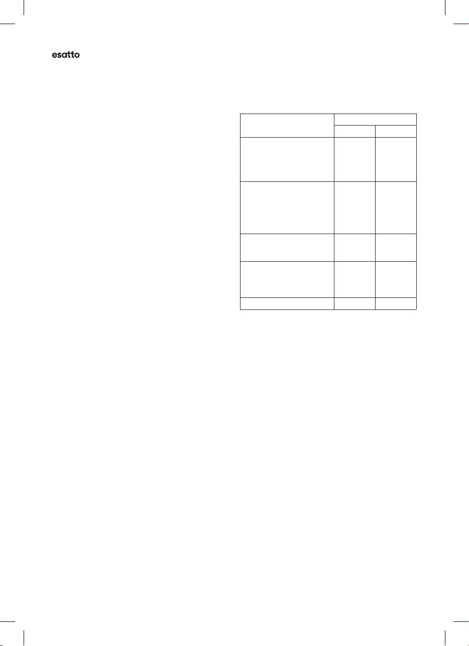
COOKTOP
FUEL TYPE:
DIMENSION A
Minimum* Maximum
Gas (multiple burners
with maximum 45.4 MJ/h
total output and no
single burner exceeding
16.2 MJ/h output)
600mm 800mm
Gas (multiple burners
with total output greater
than 45.4 MJ/h but less
than 77.8 MJ/h, and no
single burner exceeding
17.3 MJ/h output)
760mm 800mm
Gas (single burner not
exceeding 21.6 MJ/h
output)
650mm 800mm
Gas (single burner with
an output greater than
21.6 MJ/h but not
exceeding 29.2 MJ/h)
760mm 800mm
Electric 600mm 800mm
INSTALLATION PREPARATION
Before beginning the instlltion of your rngehood,
the method of ducting should be considered. This
rngehood cnnot be operted in recircultion
mode. We recommend to duct wherever possible.
Plese follow the below tips on how to correctly
duct your rngehood:
• Alwys use correctly sized ducting.
• Do not reduce the size of the ducting.
• Alwys use solid ducting.
• Alwys use non-mmble ducting.
• Alwys duct to the outside tmosphere.
• Avoid use exible ducting.
• Do not duct into the ceiling spce.
Alwys vent to the outside tmosphere.
• Avoid shrp 90 degree bends s much
s possible. Use 45 degree bends insted
wherever possible.
• Duct to the outside tmosphere using the
shortest duct run possible.
• Use cylindricl ducting whenever possible.
Ducting Options
• Into your ceiling cvity nd then vented through
your eves.
• Stright up nd through the roof.
• Through your wll.

esatto.house
11
WALL MOUNTING INSTALLATION
Prepre for instlltion
1. If you hve n outlet to the outside, your
rngehood cn be connected s below picture
by mens of n extrction duct (enmel,
luminum, exible pipe or inmmble
mteril with n interior dimeter of 150mm)
2. Before instlltion, ensure tht turn the unit
o nd unplugged from the outlet.
3. The rngehood should dhere to the minimum
nd mximum distnces from the rngehood
bse to the cooktop surfce (s per the Position
the Rngehood section on pge 10).
4. Determine the position of the three holes on
the wll.
5. Drill the three holes in the wll with the 8 mm
drill.
6. Insert the three wll plugs.
7. Attch the wll brcket to the wll plugs with
the three ST4 × 30mm screws.
Sfety holes
8. Determine the position of the two sfety holes
on the wll.
9. Drill the two sfety holes in the wll with
the 8 mm drill.
10. Insert the two wll plugs.
11. Lift up the rngehood nd hng onto the wll
brcket hook. Use the two ST4 × 30mm screws
to secure it.
12. Fix the one-wy-vlve to the ir outlet of the
rngehood. Then ttched the exhust pipe onto
the one-wy-vlve s shown below.
Wall plugs
Screws
ST4×30mm
Wall bracket
Safety holes
Wall bracket Rangehood
Rangehood
Pipe

User Manual
12
Instlltion Instructions (Continued)
Instlling the lower chimney brcket
13. Determine the position of the two chimney
brcket holes on the wll.
14. Drill the two holes into the wll using 8 mm
drill.
15. Insert the two wll plugs.
16. Attch the lower chimney brcket to the
wll plugs using the two ST4 × 30mm screws.
17. Attch the upper chimney into lower chimney,
then hnge the xing hole to the upper chimney
brcket's hooks, s shown below.
18. Then pull out the upper chimney upwrds,
djusting the height required.
Instlling the upper chimney brcket
19. Determine the position of the two chimney
brcket holes on the wll.
20.Drill the two holes into the wll using
8 mm drill.
21. Insert the two wll plugs.
22.Attch the upper chimney brcket to the
wll plugs using the two ST4 × 30mm screws.
23.Assembly the chimney onto the unit nd x it
with two ST4 × 8mm screws shown below.
Lower chimney
bracket
Wall plugs Screws
ST4×30mm
Upper chimney
bracketWall plugs
Screws
ST4×30mm
Screws
ST4×8mm

esatto.house
13
Opertion Instructions
CAUTION:
• Do not touch the light within 30 minutes fter using the pplince.
• Do not cover the lmp with therml insultion or other mterils.
CONTROL PANEL
1. Power Button
Press this button once to turn on.
Press this button twice to turn o.
2. Decrese Speed Button
Press this button to decrese the extrction speed by one power level.
NOTE: When operting on power level 1, the decrese button will chnge ny speed settings
s it is lredy on the lowest extrction speed.
3. Digitl Disply
"1" – Rngehood is extrcting t the lowest speed.
"2" – Rngehood is extrcting t medium speed.
"3" – Rngehood is extrcting t the highest speed.
NOTE: When the disply is o, the rngehood hs been powered o.
4. Increse Speed Button
Press this button to increse the extrction speed by one power level.
NOTE: When operting on power level 3, the increse button will chnge ny speed settings
s it is lredy on the highest extrction speed.
5. Light Button
Press this button to turn the light on.
Press this button gin to turn the light o.
6. Delyed Power O
To utomticlly power o your rngehood fter 5 minutes, enter the Delyed Power O setting by
long pressing the Decrese & Increse buttons together for 3 seconds. Once in the Delyed Power O
setting, the disply will blink "1", "2", "3".
To cncel the Delyed Power O setting, long press the Decrese & Increse buttons for 3 seconds
nd the disply will stop blinking.
1 42 53
6
Note: The images in this user manual are for reference only. Your appliance may appear dierently.

User Manual
14
PRIOR TO CLEANING YOUR RANGEHOOD
WARNING!
• Be sure to turn o the pplince nd remove the plug before ny mintennce is perform.
• Alwys let the pplince nd its components cool down before clening them.
• Do not use brsive wipes, chemicls or lcohol s these could dmge the surfce.
• Do not clen ny Electricl/Electronic prts .
• Do not use ny crid or corrosive detergents.
• Do not use ny brsive detergents or ny lkline dishwsher detergents!
• Mintennce nd inspection should be undertken on frequent bsis.
If there is ny visible dmge, strong odour or excessive overheting of components,
stop using the pplince.
• Clen the pplince in ccordnce with instructions. Filure to do so my result in risk of re.
RISK OF ELECTRIC SHOCK!
• Do not use stem clener.
CLEANING OF THE RANGEHOOD
TASK FREQUENCY
Clen the stinless surfce with soft cloth nd lukewrm
wter. A clening uid suitble for stinless steel my be used.
NOTE: To prevent ny criss-cross scrtches, ensure tht you
wipe long the grin of the stinless steel.
Weekly
Clen the control pnel with soft cloth nd wrm wter.
Ensure tht the cloth is clen nd is not too wet. Use dry soft
cloth to remove ny excess moisture.
Weekly
Clening the mesh lters Monthly
(See Clening the mesh lters for more
detils)
Clening the ctive crbon lter Every 3 to 6 months
(See Instlling nd replcing the crbon
lter for more detils)
Mintennce Clening

esatto.house
15
CLEANING THE MESH FILTERS
1. Remove mesh lter.
Cleaning option #1: Cleaning Manually (max 30°C)
• Sok the lter for bout 3 minutes in wter with mild non-corrosive grese-removing detergent.
• Wsh the lter seprtely from crockery nd kitchen utensils.
• Brush the lter gently with soft brush.
NOTE: Do not pply too much pressure to void dmging the lter
• Over time, fding nd discolourtion my hppen.
This is norml nd is not considered wrrnty issue.
2. Cleaning option #2: Cleaning using the dishwasher (max 30°C)
• Plce the lter in the dishwsher nd run progrm with mild non-corrosive grese-removing
detergent. NOTE: It is dvisble not to use rinse ids.
• Wsh the lter seprtely from crockery nd kitchen utensils.
• Brush the lter gently with soft brush.
NOTE: Do not pply too much pressure to void dmging the lter
• Over time, fding nd discolourtion my hppen.
This is norml nd is not considered wrrnty issue.
3. Leve the lter to dry nturlly out of direct sunlight.
4. Put the lter bck in its correct position.
INSTALLING AND REPLACING THE CARBON FILTER
The crbon lter is n optionl spre prt vilble to purchse by contcting our After Sles Support Tem.
Do not clen or wsh the crbon lters. If crbon lter
is used, we recommend replcing the crbon lter every
3 to 6 months.
To instll nd replce the crbon lter:
1. Disconnect the power supply from the wll socket.
2. Remove the mesh lter.
3. Instll or replce the ctive crbon lters
(refer to the imge on the right)
4. Plce the mesh lter bck into position.
5. Reconnect power supply to the wll socket.
REPLACING THE LIGHT GLOBE
WARNING! Only qulied electricin or service gent my replce the globe.
• Unplug ll power connections before opening the pplince.
• RISK OF BURNING! Alwys let the globe cool down before replcing it.
• Alwys use gloves or cloth to void direct contct with your hnds.
• Direct contct my reduce the lifespn of the globe.
To replce the light globe:
1. Mke sure you switch o the pplince.
2. Disconnect the power supply from the wll socket.
3. Press the lter lock nd remove the lter.
4. Replce the light globe
5. Plce the mesh lter bck into position.
6. Reconnect the power supply to the wll socket.

User Manual
16
OPERATION IN CASE OF EMERGENCY
In the event of n emergency you should:
• Switch o ll rngehood controls.
• Switch the rngehood o t the power outlet nd immeditely unplug.
• Cll After Sles Support on 1300 11 4357 or emil support@residentigroup.com.u
Some minor fults cn be fixed by referring to the instructions given in the tble below.
IMPORTANT: If your pplince ppers to be operting incorrectly, then you should disconnect it
from your electricl supply nd then contct After Sles Support.
WARNING: Do not ttempt to repir the rngehood yourself.
Plese note tht if n engineer is sked to ttend whilst the product is under wrrnty nd finds tht the
problem is not the result of n pplince fult, then you my be lible for the cost of the cll out chrge.
The pplince must be ccessible for the engineer to perform ny necessry repir.
If your pplince is instlled in such wy tht n engineer is concerned tht dmge will be cused to the
pplince or your kitchen, then they will not complete repir. This includes situtions where the rngehood
hs been tiled in or seled in with selnt.
Plese refer to the conditions of tht pper on the wrrnty crd t the rer of this user mnul.
Troubleshooting

esatto.house
17
FAULT COMMON CAUSE COMMON SOLUTIONS
The lights cn be turned on,
however the motor does not
work
Fn switch is broken Cll After Sles Support for further
guidnce.
The motor is broken
Both the light nd motor do
not work
The fuse is broken Reset or replce the fuse.
The power supply cord is loose
or disconnected
Reconnect the power supply to the
wll socket.
Oil is leking The one-wy-vlve nd exhust
pipe re not tightly sel
Disssemble the one-wy-vlve nd
sel with selnt.
There is lekge between
section nd cover
Disssemble the section nd sel
with selnt.
The light is not working The light globes re dmged
or blown
The globes need replcing.
Refer to Replcing the light globe.
The is insucient suction
power or ir is not extrcted
dequtely.
The distnce between the
rngehood nd the cooktop is
too gret.
Hve your instller re-djust the
instlltion position, ensuring tht
the minimum distnces re observed
s per the building code nd relevnt
stndrds.
Ducting is loose, kinked, too
long or too mny bends.
Check tht your rngehood hs been
ducted correctly nd in ccordnce
with the instlltion instructions.
The rngehood is no longer in
horizontl position
The screws or not tight enough Tighten the screws nd level the
rngehood in horizontl position.
The rngehood is vibrting
ginst the wll or cupbord
The rngehood undermount is
not fixed correctly.
Tighten the internl sfety screws.

User Manual
18
Attch your receipt
to this pge

esatto.house
19
Purchse Detils
For your records, plese record detils of your purchse below nd stple
your receipt on the opposite pge. Your seril number cn be found on the rer of your Rngehood.
STORE DETAILS
STORE NAME
|
ADDRESS
|
TELEPHONE
|
PURCHASE DATE
|
PRODUCT DETAILS
MODEL NO.
|
SERIAL NO.*
|

User Manual
20
WARRANTY TERMS AND CONDITIONS
RANGEHOODS
This document sets out the terms and conditions of the
product warranties for Residentia Group Appliances. It is
an important document. Please keep it with your proof of
purchase documents in a safe place for future reference
should you require service for your Appliance.
1. IN THIS WARRANTY
(a) ‘acceptable quality’ as referred to in clause 10 of
this warranty has the same meaning referred to in
the ACL;
(b) ‘ACL’ means Trade Practices Amendment (Australian
Consumer Law) Act (No.2) 2010;
(c) ‘Appliance’ means any Residentia Group product
purchased by you accompanied by this document;
(d) ‘ASR’ means Residentia Group authorised service
representative;
(e) ‘Residentia Group’ means Residentia Group Pty Ltd
of 165 Barkly Ave, Burnley VIC 3121, ACN 600 546 656
in respect of Appliances purchased in Australia;
(f ) ‘major failure’ as referred to in clause 10 of this
warranty has the same meaning referred to in the
ACL and includes a situation when an Appliance
cannot be repaired or it is uneconomic for Residentia
Group, at its discretion, to repair an Appliance during
the Warranty Period;
(g) ‘Warranty Period’ means:
(i) where the Appliance is used for personal,
domestic or household use (i.e. normal
single family use) as set out in the instruction
manual, the Appliance is warranted against
manufacturing defects for 24 months, following
the date of original purchase of the Appliance;
(h) ‘you’ means the purchaser of the Appliance not
having purchased the Appliance for re-sale, and ‘your’
has a corresponding meaning.
2. This warranty only applies to Appliances purchased
and used in Australia and is in addition to (and does
not exclude, restrict, or modify in any way) any
non-excludable statutory warranties in Australia.
3. During the Warranty Period Residentia Group or
its ASR will, at no extra charge if your Appliance
is readily accessible for service, without special
equipment and subject to these terms and conditions,
repair or replace any parts which it considers to
be defective. Residentia Group or its ASR may use
remanufactured parts to repair your Appliance. You
agree that any replaced Appliances or parts become
the property of Residentia Group. This warranty does
not apply to light globes, batteries, lters, seals or
similar perishable parts.
4. Parts and Appliances not supplied by Residentia
Group are not covered by this warranty.
Wrrnty
— THIS WARRANTY IS VALID IN AUSTRALIA ONLY —
This manual suits for next models
1
Table of contents
Other Esatto Ventilation Hood manuals

Esatto
Esatto ERCB90TBS User manual

Esatto
Esatto ERU90S User manual

Esatto
Esatto ERU52TB User manual

Esatto
Esatto ERU52TB User manual

Esatto
Esatto ERCB90TS User manual

Esatto
Esatto ERF60W User manual

Esatto
Esatto ERCB90TS User manual

Esatto
Esatto ERC603S User manual

Esatto
Esatto ESL60DRS User manual

Esatto
Esatto ERF60S User manual
Popular Ventilation Hood manuals by other brands

Heinner
Heinner DCH-650RIX manual

Swegon
Swegon CASA Smart Blues Instructions for use

Hearth and Home Technologies
Hearth and Home Technologies Heat Recovery Ventilator HRV200PLUS Installation and operating instructions

Wolf
Wolf Downdraft Ventilation Use & care guide

IKEA
IKEA SVÄVANDE manual

inventum
inventum AKE9004ARVS instruction manual