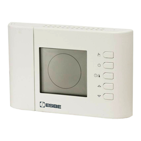
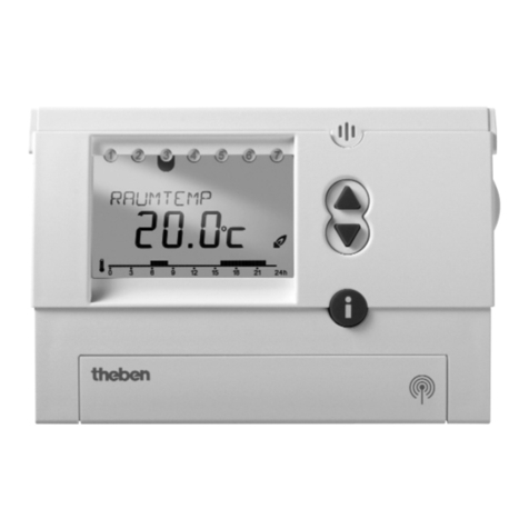
ESBE TPE214 User manual

- ITALIANO -
TRD02B0002EV 029374 091117
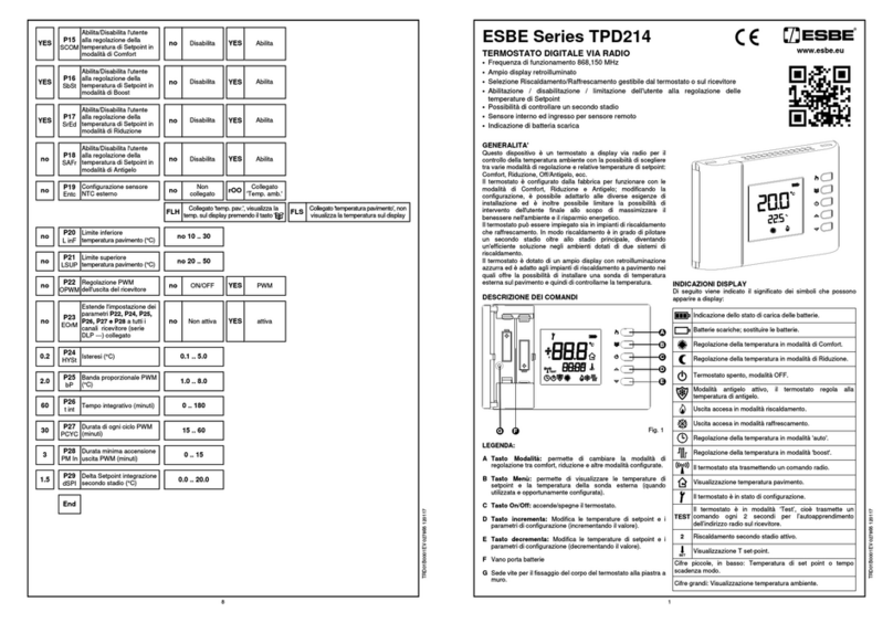
DESCRIZIONE DEI COMANDI
LEGENDA:
A Tasto ' 4 ': Tasto multifunzione
Normale funzionamento
- Se premuto una olta isualizza la temperatura di
set-point impostata.
- Se premuto ripetutamente modifica le temperature di
set-point (incrementando il alore).
In configurazione
- Se premuto una olta isualizza il parametro impostato.
- Se premuto ripetutamente modifica il parametro
selezionato (incrementando il alore).
B Tasto ' ': tasto multifunzione
Normale funzionamento
- Imposta la modalità di regolazione (in accordo con il
parametro P02):
Comfort => Riduzione => OFF/ANTIGELO.
- Se premuto per 10 secondi in erte la logica di
funzionamento: Riscaldamento Raffrescamento.
In configurazione
- Visualizza i parametri configurabili
C Tasto ' 3 ': Tasto multifunzione
Normale funzionamento
- Se premuto una olta isualizza la temperatura di
set-point impostata.
- Se premuto ripetutamente modifica le temperature di
set-point (decrementando il alore).
In configurazione
- Se premuto una olta isualizza il parametro impostato.
- Se premuto ripetutamente modifica il parametro
selezionato (decrementando il alore).
INDICAZIONI DISPLAY
Di seguito iene indicato il significato dei simboli che possono
apparire a display:
Indicazione dello stato di carica delle batterie.
Batterie scariche; sostituire le batterie.
Regolazione della temperatura in modalità di Comfort.
Regolazione della temperatura in modalità di
Riduzione.
Termostato spento, modalità OFF.
Modalità antigelo atti o, il termostato regola alla
temperatura di antigelo.
Uscita accesa in modalità riscaldamento.
Uscita accesa in modalità raffrescamento.
Regolazione della temperatura in modalità 'auto'.
Il termostato sta trasmettendo un comando radio.
Il termostato è in stato di configurazione.
Il termostato è in modalità ‘Test’, cioè trasmette un
comando ogni 2 secondi per l’autoapprendimento
dell’indirizzo radio sul rice itore.
Visualizzazione T set-point.
EEE Con P10 impostato su EXT, il sensore esterno
utilizzato è guasto o non collegato.
GENERALITA'
Questo dispositi o è un termostato a display ia radio per il
controllo della temperatura ambiente con la possibilità di
scegliere tra arie modalità di regolazione e relati e
temperature di set-point: Comfort, Riduzione, Off/Antigelo.
Il termostato è configurato dalla fabbrica per funzionare con le
modalità di Comfort, Riduzione e Antigelo; modificando la
configurazione, è possibile adattarlo alle di erse esigenze di
installazione ed è inoltre possibile limitare la possibilità di
inter ento dell'utente finale allo scopo di massimizzare il
benessere nell'ambiente e il risparmio energetico.
Il termostato può essere impiegato sia in impianti di
riscaldamento che raffrescamento.
Il termostato è adatto anche agli impianti di riscaldamento a
pa imento.
MESSA IN FUNZIONE
Alla prima messa in funzione aprire il termostato, come indicato
nel paragrafo 'INSTALLAZIONE' IN (C di Fig. 6), e inserire le
pile rispettando le polarità indicate. Le pile de ono essere del
tipo AA 1.5V alcaline.
Im ostazione Riscaldamento / Raffrescamento
Il termostato è impostato dalla fabbrica in modalità
riscaldamento.
Per modificare la modalità di regolazione tenere premuto per
10 secondi il pulsante ' '.
A. Se precedentemente il termostato era impostato su
riscaldamento, errà impostata la modalità di raffrescamento
e sul display lampeggerà il simbolo ' ' per 8 secondi.
B. Se precedentemente il termostato era impostato su
raffrescamento, errà impostata la modalità di riscaldamento
e sul display lampeggerà il simbolo ' ' per 8 secondi.
Durante il normale funzionamento, l’atti azione del
riscaldamento iene segnalata dall’icona ' ' (Fiamma) mentre,
al contrario l’atti azione del raffrescamento iene segnalata
dall’icona ' ' (Ne e).
Nel caso il termostato sia configurato per funzionare con un
cronotermostato in un sistema radio New Wa e, non sarà
possibile modificare l'impostazione riscaldamento/
raffrescamento in quanto essa è definita sul cronotermostato o
sul modulo relè.
Im ostazione modalità di regolazione
Le modalità per regolare la temperatura ambiente sono 3 e
possono essere scelte mediante la pressione del tasto ' '.
Comfort: Il termostato regola la temperatura
ambiente secondo la modalità di comfort, di
solito è la temperatura desiderata durante le
ore diurne.
Riduzione / Auto: Il termostato regola la temperatura
ambiente secondo la modalità di riduzione,
di solito è la temperatura desiderata durante
le ore notturne, se il parametro P01 è
impostato su trA. Al contrario, se il
parametro P01 è impostato su rEC il
termostato regola la temperatura ambiente
secondo le modalità di comfort o di
riduzione a seconda del programma orario
impostato sul cronotermostato associato.
OFF / Antigelo: Disatti a il termostato; il display mostrera' la
scritta ' OFF '. Se il termostato e' stato
impostato in modalità di riscaldamento sara'
atti a la funzione antigelo e sul display
comparirà il simbolo ' '; in tal caso la
temperatura ambiente sarà regolata
secondo il alore impostato per la
temperatura di antigelo, nel parametro P03
( edere il paragrafo 'CONFIGURAZIONE
INSTALLATORE').
Il termostato è configurato dalla fabbrica per utilizzare le
modalità di OFF, Comfort e Riduzione.
Modificando il parametro installatore P02 è possibile disatti are
la selezione di una o più modalità ( edere il paragrafo
'CONFIGURAZIONE INSTALLATORE').
Premendo il tasto ' ' si cicla tra le arie modalità di
regolazione atti ate:
Una olta impostata una modalità di regolazione essa rimane
impostata fino a che non si preme ancora il tasto ' '.
Per maggiori istruzioni su come configurare le modalità di
regolazione, edere il paragrafo 'CONFIGURAZIONE
INSTALLATORE'.
Tem erature di set- oint
Fig. 2
Durante il normale funzionamento il display isualizza la
temperatura ambiente rile ata e l'icona relati a alla modalità di
regolazione impostata. Per isualizzare la relati a temperatura
di set-point impostata premere uno dei tasti '3' o '4': il display
isualizza la temperatura di set-point e si accende l'icona ' ' (a
indicare che si sta isualizzando la temperatura di set-point).
L'icona ' ' si accende assieme all'icona ' ' a indicare che il
display sta isualizzando la temperatura di set-point 'Comfort'
oppure si può accendere assieme all'icona ' ' a indicare che il
display sta isualizzando la temperatura di set-point
'Riduzione'.
Premendo i tasti '3' e '4' si modifica la temperatura di set-point
isualizzata. Premendo il tasto '3' o '4' le cifre della
temperatura di set-point iniziano a lampeggiare per indicare
che il set-point può essere modificato.
Premendo il tasto ' ' mentre il display sta isualizzando la
temperatura di set-point 'Comfort', il display passa a
isualizzare il set-point 'Riduzione'. Vice ersa se il display
sta a isualizzando il set-point 'Riduzione', premendo il tasto
' ' il display passa a isualizzare il set-point 'Comfort'.
Premendo ulteriormente il tasto ' ' oppure dopo alcuni
secondi di inatti ità, il display ritorna a isualizzare la
temperatura ambiente.
SENSORE NTC ESTERNO
Il termostato possiede un ingresso ('REMOTE SENSOR', B di
Fig. 6) per il collegamento di un sensore NTC esterno
(opzionale) oltre al sensore interno.
Il sensore esterno può essere usato per rile are la temperatura
ambiente nel caso il termostato debba essere installato in una
posizione non adatta alla rile azione della temperatura
ambiente.
Nel caso in cui l'installazione pre eda un montaggio con sonda
a distanza, è necessario impostare correttamente il parametro
P10 e collegare una sonda di tipo NTC da 4700 ohm a 25°C. In
caso di dubbio sul tipo di sonda da collegare si prega di
consultare il costruttore.
Il termostato esce dalla fabbrica predisposto per il
funzionamento con sonda interna.
CONFIGURAZIONE DEL SISTEMA RADIO
Verificare sul paragrafo 'COMPATIBILITÀ CON SISTEMA
RADIO NEW WAVE', che il rice itore da accoppiare al
termostato sia compatibile.
Prima di installare il termostato ia radio nella posizione
desiderata, è necessario controllare che il rice itore rice a
correttamente i suoi segnali. L’operazione si effettua atti ando
la funzione 'Test' premendo contemporaneamente i tasti '3' e
'4'.
In modalità 'Test' il termostato isualizza sul display la scritta
'TEST' e trasmette continuamente al rice itore comandi di
accensione e spegnimento con una pausa tra l’uno e l’altro di
circa 2 secondi; ogni olta che il termostato trasmette un
comando radio sul display si accende il simbolo ' '.
La modalità 'Test', può essere terminata in ogni momento
premendo il tasto ' '.
In ogni caso la modalità 'Test' termina automaticamente dopo
circa 17 minuti.
La modalità 'Test' de e essere usata per auto-apprendere
l’indirizzo del termostato sul rice itore e successi amente nel
rice itore il relè della relati a uscita de e continuamente
accendersi e spegnersi ogni 2 secondi, lo stato è indicato
anche dal relati o Led. Se questo a iene, il termostato
comunica correttamente con il rice itore.
Quando si posiziona il termostato nella zona desiderata,
assicurarsi che i due dispositi i comunichino ancora
correttamente.
Se il termostato iene posizionato troppo lontano dal rice itore,
il relè di uscita rimarrà sempre acceso o sempre spento: in
questo caso si consiglia di tro are una migliore posizione
magari più icina al rice itore, ed assicurarsi che non sia in
icinanza di schermi metallici, o di mura in cemento armato che
potrebbero indebolire la trasmissione radio.
La qualità del segnale può essere monitorata nel rice itore (per
maggiori informazioni, edere la relati a documentazione).
ASSOCIAZIONE CON UN CRONOTERMOSTATO
In un sistema radio New Wa e, formato da un un modulo
rice itore a più canali, un cronotermostato e più termostati
semplici, è possibile far regolare la temperatura ambiente ai
termostati secondo il programma orario impostato sul
cronotermostato.
Ciò si può ottenere associando sul rice itore le uscite
controllate dai termostati a quella del cronotermostato. In
questo modo un cronotermostato e i termostati ad esso
associati formano una ‘zona’.
Per esempio in un’abitazione si potrebbe creare una zona
giorno e una zona notte con regolazione su più stanze secondo
fasce orarie di erse programmabili su due cronotermostati.
I canali associati rice eranno dal cronotermostato
l’informazione di quale modalità di regolazione utilizzare e
quindi di quale temperatura regolare, comfort o ridotta, ma
anche spento o antigelo.
Se il cronotermostato sta regolando ad una temperatura di
Comfort, i termostati associati regoleranno secondo il loro set-
point Comfort, se in ece il cronotermostato sta regolando una
temperatura ridotta i termostati associati regoleranno con la
loro temperatura di riduzione. Analogamente se il
cronotermostato è spento con funzione di antigelo a 5°C, anche
i termostati associati regoleranno la temperatura di antigelo
5°C.
Anche il termostato a display può a ere l'uscita associata ad un
cronotermostato e quando è impostato in modalità
'Auto' (simbolo ' ' acceso), il rice itore regolerà con la
modalità di regolazione rice uta dal cronotermostato.
Quando si intende utilizzare il termostato in associazione con
un cronotermostato è necessario che il parametro P01 sia
impostato a 'rEC'.
Vedere le istruzioni del modulo rice itore per la procedura di
associazione.
CONFIGURAZIONE INSTALLATORE
La configurazione installatore permette di definire il
funzionamento del termostato per adattarlo ai di ersi tipi di
ambienti e ai di ersi tipi di impianti.
Per accedere alla configurazione, tenere contemporaneamente
premuti i tasti '4' e ' ' per alcuni secondi finché sul display
non appare il simbolo ' ' e la scritta 'Con' (configurazione).
Da questo momento, premendo il tasto ' ', si scorre tra i ari
parametri installatore identificati con ' P ' e dal numero del
parametro, da P01 a P18.
La fine della configurazione iene indicata con la scritta 'End'
OFF /
C
SET
TEST
1
•
Frequenza di funzionamento 868,150 MHz
•
Display con retroilluminazione azzurra
•
Selezione Riscaldamento/Raffrescamento gestibile
dal termostato o sul rice itore
•
Limitazione dell'utente alla regolazione delle
temperature di set-point
•
Sensore interno ed ingresso per sensore remoto
•
Indicazione di batteria scarica
SET
TEST
C
Fig. 1
B
A
C
SET
TEST
F
C
ESBE Series TPE214
TERMOSTATO DIGITALE VIA RADIO

- ITALIANO -
TRD02B0002EV 029374 091117
quindi ripremendo ulteriormente il tasto ' ' la configurazione
iene sal ata e il termostato passa al normale funzionamento.
In qualsiasi momento, tenendo premuto per qualche secondo il
tasto ' ', si può uscire dal menù di configurazione senza
sal are le modifiche effettuate.
Durante lo scorrimento dei parametri, premendo una olta il
tasto, il display isualizza l'impostazione attuale del parametro.
Per modificare la configurazione del parametro selezionato
utilizzare i tasti '3' o '4'; tenendo premuto i tasti '3' o '4' si
incrementa o decrementa il alore elocemente.
Dopo la fine e il sal ataggio della configurazione, iene a iata
automaticamente la procedura di ' TEST ' durante la quale il
termostato comunica al rice itore alcune informazioni di
configurazione dell'uscita le quali erranno sal ate in modo non
olatile dal rice itore e utilizzate per regolare la temperatura
nella modalità desiderata.
Quindi è importante eseguire l'autoapprendimento sul rice itore
prima di modificare la configurazione e alla fine della
configurazione è importante erificare che il rice itore rice a
correttamente i comandi di ' TEST '.
Reset configurazione installatore
Per effettuare il reset della configurazione installatore, in modo
da portare tutti i parametri ai alori di default impostati in
fabbrica, accedere alla configurazione e quando il display
isualizza 'Con' premere contemporaneamente i due tasti '3' e
'4' per alcuni secondi fino a che la schermata torna alla
isualizzazione normale.
Descrizione arametri di configurazione
I parametri della configurazione installatore sono illustrati nella
tabella 1 e di seguito spiegati.
E' ossibile che alcuni arametri installatore non vengano
visualizzati erché vengono ro osti solo i arametri
necessari all'attuale configurazione (il modo di configurare
un arametro uò escludere uno o iù dei arametri
successivi).
P01: permette di utilizzare la modalità riscaldamento /
raffrescamento del termostato (trA) o del rice itore (rEC).
Questo parametro a modificato a ' rEC ' (rice itore) solo
quando si intende utilizzare il termostato in associazione con
un cronotermostato in un sistema radio New Wa e o si intende
utilizzare l'ingresso esterno di selezione riscaldamento/
raffrescamento o l’ingresso riduzione dei moduli a relè New
Wa e.
P02: permette di personalizzare le modalità di regolazione che
potranno essere richiamate con il pulsante ' '. Le modalità
di regolazione sono Comfort, Riduzione e OFF, e possono
essere abilitate o disabilitate singolarmente modificando P02.
La modalità Riduzione sarà sostituita dalla modalità Auto nel
caso P01 sia configurato a 'rEC'.
La modalità OFF sarà sostituita dalla modalità Antigelo nel
caso P03 sia configurato con una temperatura di antigelo.
P03: con questo parametro è possibile impostare la
temperatura di antigelo, che errà mantenuta quando il
termostato è spento.
La temperatura di antigelo è impostabile nel range 0.5 .. 25 °C
oppure può essere disabilitata configurando il parametro fino a
far apparire il alore ‘no’.
Il dispositi o è impostato dalla fabbrica a 6 °C.
P04: offset temperatura ambiente.
Con l’offset è possibile correggere la temperatura ambiente
rile ata di ±10,0 °C, in modo da correggere e entuali errori
sistematici di lettura do uti ad un e entuale posizionamento del
termostato in zone inadatte a rile are la temperatura
dell’ambiente.
Il dispositi o è impostato dalla fabbrica con l’offset a 0,0°C.
P05: tempo di campionamento.
Per garantire una lunga durata delle pile, il termostato aspetta
un periodo di tempo tra una trasmissione e l’altra che può
essere scelto tra 3 o 10 minuti.
E’ quindi normale che la temperatura isualizzata non enga
aggiornata immediatamente e che per edere accendersi o
spegnersi l’uscita si debba aspettare il periodo di tempo
impostato.
L’opzione dei 3 minuti do rebbe essere scelta in caso di utilizzo
con sistemi di riscaldamento/raffrescamento eloci, mentre con
i comuni sistemi di riscaldamento a termosifone o a pa imento,
anche l’opzione 10 minuti consente un’ottima accuratezza e
comfort. In ogni caso, in qualsiasi momento, premendo il tasto
' ' si può forzare un aggiornamento.
Scegliendo il periodo più lungo si a rà una durata delle batterie
più lunga.
P06 e P07: questi due parametri configurano il range di
temperatura entro cui è possibile impostare la temperatura di
set-point quando il termostato è in modalità di riscaldamento. In
particolare P06 è il limite inferiore e può essere configurato
liberamente nel range 5.0°C .. 35.0°C, mentre P07 è il limite
superiore che può essere configurato in un range che parte dal
limite inferiore, scelto in P06, fino a 35.0°C.
Il range massimo è di conseguenza 5°C .. 35°C e può essere
facilmente ristretto secondo le esigenze dell’installazione.
P08 e P09: questi due parametri configurano il range di
temperatura entro cui è possibile impostare la temperatura di
set-point quando il termostato è in modalità di raffrescamento
con la stessa logica dei due punti precedenti.
Al cambiare dell’impostazione raffrescamento/riscaldamento
erranno automaticamente ridefiniti i limiti della temperatura di
set-point. Nel caso in cui la selezione raffrescamento/
riscaldamento sia sul rice itore (P01=rEC) questi due parametri
non erranno usati e saranno sempre usate le impostazioni dei
parametri P06 e P07.
P10: configurazione sensore NTC.
Il termostato esce dalla fabbrica predisposto per il
funzionamento con sonda interna (P10= Int).
In alternati a alla sonda interna è possibile collegare una sonda
remota al connettore 'REMOTE SENSOR', indicato con B in
Fig. 5 ed impostare questo parametro su 'Ext': in questo modo
si disabilita la sonda interna e si abilita quella remota.
Assicurarsi di usare il giusto tipo di sonda remota, e rispettare
la lunghezza massima dei fili ammessa.
P11: regolazione PWM dell'uscita, permette di scegliere se
COMPATIBILITÀ CON SISTEMA RADIO NEW WAVE
Il termostato funziona con i rice itori radio New Wa e con le
seguenti limitazioni sulle ersioni di firmware (FW):
DAPF84 (antenna atti a): tutti
DAPF84 (ripetitore): da FW. 021023A1 e
successi i
DLP841M (modulo 8 canali) da FW 020842A1 e
successi i
DLP841M001 (modulo 8 canali) tutti
DLP8412 (modulo 8 canali): tutti
DLP241M (modulo 2 canali): da FW 020843A1 e
successi i
DLP241M001 (modulo 2 canali): tutti
DRPF84M01 (rice itore un canale): da FW 021057A1 e
successi i
DRPF84M011 (rice itore un canale): tutti
Versioni successi e di firmware sono identificate con un
numero superiore (escluso A1 finale).
CARATTERISTICHE TECNICHE
Alimentazione: 2 x 1,5V pile alcaline tipo AA
Durata Batterie: 5 anni con P05=10 minuti
3 anni con P05=3 minuti
Frequenza: 868,150 MHz
Modulazione: GFSK
Max. potenza RF trasmessa: 1 mW
Tipo antenna: Interna
Max. distanza dal rice itore: >300 m in campo libero
>50 m all’interno di edifici
dipendente dall’edific io e
dall’ambiente)
Temperatura ambiente (sensore interno o remoto in alternati a)
Campo di regolazione: 5,0 .. 35,0°C
Isteresi: 0,2°C configurabile 0,1 .. 5,0 °C
Tipo di sensore: NTC 4K7 Ohm ±1% @ 25°C
Risoluzione: 0,1°C
Range: -9,9°C .. +50,0°C
Precisione: ±1,0°C
Massima lunghezza dei fili
erso il sensore remoto: 15 m
Antigelo: configurabile OFF|0.5 .. 25.0 °C
6.0°C (default)
Offset: ± 10.0°C. (Default 0.0°C)
Spegnimento
retroilluminazione: 20 secondi da ultima pressione
Grado di protezione: IP 30
Tipo di azione: 1
Categoria di so ratensione: II
Grado di inquinamento: 2
Indice di traking (PTI): 175
Classe di protezione contro
le scosse elettriche: III
Tensione impulsi a
Nominale: 2500V
Numero di cicli manuali: 50000
Numero di cicli automatici: nessun limite
Classe del software: A
Tensione pro e EMC: 3V
Corrente pro e EMC: 35mA
Tolleranze distanze esclusione
modo guasto ‘corto’: ±0,15mm
Temperatura pro a sfera: 75° C
Temp. di funzionamento: 0°C .. +40°C
Temperatura di stoccaggio: -10°C .. +50°C
Limiti di umidità: 20% .. 80% RH non condensante
Contenitore: Materiale: ABS+PC V0 autoestinguente
Colore: Bianco segnale (RAL 9003)
Peso: ~ 115 gr
CLASSIFICAZIONE SECONDO REGOLAMENTO
2013.811.CE
Classe: IV
Contributo all’efficienza energetica: 2%
DIMENSIONI
GARANZIA
Nell'ottica di un continuo s iluppo dei propri prodotti, il
costruttore si riser a il diritto di apportare modifiche a dati
tecnici e prestazioni senza prea iso.
Il consumatore è garantito contro i difetti di conformità del
prodotto secondo la Diretti a Europea 1999/44/c nonché il
documento sulla politica di garanzia del costruttore. Su
richiesta è disponibile presso il enditore il testo completo della
garanzia.
l'uscita del rice itore de e essere pilotata in modo ON/OFF o
PWM (Pulse Width Modulation).
Con regolazione ON/OFF (no) si a rà una regolazione con
isteresi personalizzabile sul parametro P13, mentre con
regolazione PWM (YES) si a rà una regolazione proporzionale
che è possibile adattare ai ari ambienti con i parametri banda
proporzionale, tempo integrati o, e tempo del ciclo.
P12: estende il modo di pilotaggio dell'uscita agli altri canali,
questo parametro ha significato solo se il termostato è stato
accoppiato con un rice itore a più canali (DLP ---).
Se questo parametro iene impostato su 'YES', tutti i canali del
rice itore erranno configurati con l'impostazione ON/OFF o
PWM scelta al parametro P11 ed i relati i parametri da P13 a
P17 isteresi, banda proporzionale, tempo integrati o, e tempo
del ciclo. In questo modo si può usare il termostato per
configurare il modo di pilotaggio dell'uscita non solo del canale
su cui è stato fatto l'autoapprendimento, ma anche degli altri
canali disponibili sul rice itore. In questo modo si può
cambiare, per esempio, l'isteresi del rice itore o fare di entare
un'uscita PWM anche se il canale poi errà pilotato da un
termostato semplice non configurabile.
P13: isteresi, rappresenta l'ampiezza dell'isteresi che errà
utilizzata quando in P11 si sceglie una regolazione ON/OFF
(no).
P14: banda proporzionale PWM, iene utilizzata per la
regolazione proporzionale quando, in P11, l'uscita è configurata
per essere pilotata con PWM (YES).
P15: tempo integrati o in minuti, iene utilizzato per la
regolazione proporzionale quando, in P11, l'uscita è configurata
per essere pilotata con PWM. Se impostato a zero non si ha
nessuna azione integrati a.
P16: tempo ciclo PWM, è la durata in minuti di ogni ciclo PWM,
cioè ogni quanti minuti iene ripetuto l'impulso a larghezza
ariabile.
P17: minimo tempo ON del PWM, cioè la minima larghezza
dell'impulso PWM o ero il tempo minimo di accensione
dell'uscita. Nel caso in cui sia collegato un attuatore
elettrotermico, questo parametro a impostato con il tempo di
apertura dell'attuatore, altrimenti accensioni per tempi inferiori
al tempo di apertura non generano azioni apprezzabili in uscita.
P18: isualizzazione di default della temperatura di set-point. Il
termostato è impostato di fabbrica sul parametro “no”, o ero il
termostato isualizza la temperatura ambiente rile ata, ma se
questo parametro iene impostato su “YES”, la temperatura
isualizzata è quella di set-point, ma può comunque essere
isualizzata momentaneamente la temperatura ambiente dopo
che si è modificata la temperatura di set-point. In ece, se il
parametro è impostato su “OnL”, “solo set-point”, il termostato
isualizza solamente le temperature di set-point (set-point
comfort, set-point riduzione) e non è possibile isualizzare la
temperatura ambiente.
REGOLAZIONE DELLA TEMPERATURA
Il termostato è in grado di pilotare l'uscita sul rice itore in modo
ON/OFF o PWM. Il pilotaggio della al ola in modo PWM
permette di effettuare una regolazione proporzionale e quindi
regolare la temperatura ambiente con il massimo comfort e
risparmio.
Tutta ia ambienti di ersi necessitano di impostazioni di erse al
fine di ottenere una regolazione precisa.
I parametri responsabili della qualità della regolazione sono:
- P14 Banda proporzionale
- P15 Tempo di integrazione
La banda proporzionale, espressa in °C, è quella differenza tra
set-point e temperatura ambiente che fa sì che il regolatore
apra tutta la al ola. Tanto più stretta è la banda proporzionale
tanto più è reatti o il sistema al ariare della temperatura
ambiente. Un’impostazione della banda proporzionale troppo
stretta può generare oscillazioni della temperatura ambiente o
instabilità del sistema. Un’impostazione troppo larga può
portare a non raggiungere nell’ambiente la temperatura
impostata sul set-point. Quando il tempo di integrazione è
impostato a zero non si ha nessuna azione integrati a, e la
regolazione è di tipo P (Proporzionale).
Impostando un tempo di integrazione di erso da zero la
regolazione sarà di tipo P + I (Proporzionale + Integrale). Tanto
più piccolo è il tempo integrale tanto più grande è l’azione
integrale, ice ersa un tempo integrale lungo genera un’azione
integrale blanda. Un’azione integrale blanda o assente può far
sì che non si riesca a raggiungere nell’ambiente la temperatura
impostata sul set-point. Un’azione integrale troppo forte può
generare delle oscillazioni della temperatura ambiente. Può
essere necessario ritoccare questi parametri a seconda
dell’ambiente in cui si opera al fine di ottenere la migliore
regolazione.
RETROILLUMINAZIONE DISPLAY
L’accensione della retroilluminazione del display si erifica in
seguito alla pressione di un qualsiasi pulsante. Lo spegnimento
è automatico dopo 20 secondi dall’ultima pressione del
pulsante.
INSERIMENTO / SOSTITUZIONE BATTERIE
Il display mostra costantemente lo stato di carica delle batterie
tramite il simbolo ' '. La carica delle batterie è massima
se all’interno del simbolo tutti e tre gli indicatori di li ello sono
accesi.
Al contrario le batterie sono scariche e de ono essere sostituite
quando il simbolo appare completamente uoto ' '.
Il simbolo ' ' lampeggia nel caso in cui le batterie siano
troppo scariche per permettere una trasmissione radio.
Per la sostituzione delle batterie procedere come indicato nei
punti 1, 2 e 4 a pagina 3.
23.6mm85mm
85mm
2

- ITALIANO -
TRD02B0002EV 029374 091117
Tabella 1
: Configurazione installatore
Riassunto dei parametri costituenti la configurazione.
CON
Dati di
Default
End
INSTALLAZIONE
a
ATTENZIONE
- Prima di rocedere con l’installazione del termostato
assicurarsi che i segnali radio trasmessi siano
correttamente ricevuti dall’unità ricevente.
- Affinché la regolazione della tem eratura ambiente
avvenga correttamente, installare il termostato a circa
1,5 m dal avimento, lontano da sorgenti di calore,
correnti d’aria, e areti articolarmente fredde ( onti
termici). Quando viene usato il sensore remoto er
acquisire la tem eratura ambiente queste note sono da
a licarsi alla osizione dello stesso.
- La connessione con un sensore remoto deve essere
effettuata usando fili con sezione di almeno 1,5 mm² e
non iù lunghi di 15 metri. Non usare la stessa
canalizzazione er segnale del sensore e tensione di rete.
- L’installazione ed il collegamento elettrico del
termostato devono essere eseguiti da ersonale
qualificato ed in conformità alle leggi vigenti.
Fig. 3
Spingere, con l’aiuto di un caccia ite, la linguetta plastica
situata nella feritoia posta sul lato sinistro, fino a solle are
leggermente la calotta (Fig. 3).
1
Fig. 4
Ruotare la calotta esercitando una leggera pressione fino
ad estrarla completamente (Fig. 4).
2
Co nfigurare il termos t ato, edi paragrafo
'CONFIGURAZIONE INSTALLATORE'.
6
Richiudere il termostato eseguendo le seguenti
operazioni:
- Posizionare i due dentini della parte destra della calotta
negli appositi intagli.
- Ruotare la calotta e spingere erso l’interno, con un
dito, la linguetta plastica posta sulla parte sinistra della
base (indicata dalla freccia in Fig. 8) ed esercitare una
pressione che faccia scattare la linguetta plastica di
fissaggio all’interno dell’apposito foro.
5
Fig. 8
2
1
1
3
P04
-10.0 .. +10.0 0.0
OFFSET: Correzione temperatura ambiente (°C)
P06
5.0 .. 35.0 8.0
Temperatura Set-point limite inferiore riscaldamento (°C)
P07
5.0 .. 35.0 29.0
Temperatura Set-point limite superiore riscaldamento (°C)
P08
5.0 .. 35.0 10.0
Temperatura Set-point limite inferiore raffrescamento (°C)
P09
5.0 .. 35.0 35.0
Temperatura Set-point limite superiore raffrescamento (°C)
P03
no | 0.5 .. 25.0
6.0
Set-point temperatura di antigelo (°C)
P05
3 | 10
10
Tempo di campionamento (minuti)
P10
Sensore NTC
remoto
Ext
Sensore NTC
interno
Int Int
Configurazione sensore NTC
P12
Non atti a
no
atti a
YES no
Estende l'impostazione dei parametri P11, P13, P14, P15,
P16 e P17 a tutti i canali rice itore (serie DLP ---) collegato
P11
PWM
YES
ON/OFF
no no
Regolazione PWM dell'uscita del rice itore
P13
0.1 .. 5.0
0.2
Isteresi (°C)
P14
1.0 .. 8.0
2.0
Banda proporzionale PWM (°C)
P15
0 .. 180 60
Tempo integrati o (minuti)
P16
15 .. 60
30
Durata di ogni ciclo PWM (minuti)
P17
0 .. 15
3
Durata minima accensione uscita PWM (minuti)
Indi iduare la migliore posizione di installazione ( edere
paragrafo 'CONFIGURAZIONE DEL SISTEMA RADIO),
quindi fissare la base del termostato alla parete tramite le
due sedi per iti con interasse 60 mm (utilizzare le iti e/o i
tasselli in dotazione) facendo passare i fili dell'e entuale
sonda remota tramite l'apertura rettangolare (A di Fig. 5).
3
Fig. 5
60mm
A
60 mm
- Inserire correttamente le batterie (rispettando la corretta
polarità) nel ano batterie (C di Fig. 6), non usare pile
scariche, usare pile alcaline.
- Eseguire il collegamento elettrico dell'e entuale sonda
remota utilizzando il connettore 'REMOTE SENSOR' (B
di Fig. 6), seguendo lo schema di collegamento di
Fig. 7; quindi impostare correttamente il parametro P10.
Leggere il paragraf o 'CONFIGURAZIONE
INSTALLATORE'.
4
P01
Trasmettitore
trA trA
Selezione Riscaldamento / Raffrescamento Rice itore
rEC
P02
CrO
Comfort -
Riduzione - Off
CrO
Riduzione - Off
rO
Comfort -
Riduzione
Cr
Comfort - Off
C O
Off
O
Riduzione
r
Comfort
C
Abilitazione modalità di regolazione
3
P18
Vis. set-point
YES
Vis. Ta.
no no
Visualizzazione di default della temperatura set-point
B
C
Fig. 6 Fig. 7
Vis. solo set –point
OnL
www.esbe.eu

- ENGLISH -
TRD02B0002EV 029374 091117
Table 1:
Installer configuration
Summary of the configuration parameters.
CON
Default
data
INSTALLATION
a
WARNING
-
Make sure that the transmitted radio signals are
correctly received by the receiving unit before installing
the thermostat.
- Install the thermostat at about 1.5 m from the floor,
away from heat sources, draught and articularly cold
walls (heat bridges), for the room tem erature to be
regulated correctly. These notes must be a lied to
lace the remote sensor when this is used to acquire
the room tem erature.
- A remote sensor must be connected using wires having
at least 1.5 mm² section and no longer than 15
metres. Do not use the same i es for sensor signals
and mains voltage.
- The installation and electrical connection of the
thermostat must be erformed by qualified ersonnel
and in com liance with current standards.
Fig. 3
Push, with the help of a screwdri er, the plastic tooth
located in the slot on the left side, then lift the plastic
co er (Fig. 3).
1
Fig. 4
Turn the co er, while pressing it slightly, until it is fully
extracted (Fig. 4).
2
Configure the thermostat: see "INSTALLER
CONFIGURATION" paragraph.
6
Close the thermostat as follows:
- Match the two teeth located in the right side of the
plastic base with the two slots located on the plastic
co er.
- Close the left side of the co er while slightly pressing
with a finger, at the same time, the plastic tooth on the
left side to the internal (see the arrow in Fig. 8).
Complete the rotation of the co er until the plastic tooth
on the base snaps into the rele ant hole of the co er.
5
Fig. 8
2
1
1
3
P04
-10.0 .. +10.0 0.0
OFFSET: Room temperature correction (°C)
P06
5.0 .. 35.0 8.0
Temperature Set-point lower limite heating (°C)
P07
5.0 .. 35.0 29.0
Temperature Set-point upper limit heating (°C)
P08
5.0 .. 35.0 10.0
Temperature Set-point lower limite cooling (°C)
P09
5.0 .. 35.0 35.0
Temperature Set-point upper limit cooling (°C)
P02
CrO
Comfort -
Economy - Off
CrO
Economy -
Off
rO
Comfort -
Economy
Cr
Comfort - Off
C O
Off
O
Economy
r
Comfort
C
Allowed regulation modes setting
P03
no | 0.5 .. 25.0
6.0
Antifrost temperature set-point (°C)
P05
3 | 10
10
Sampling time (minutes)
P10
Remote NTC
sensor
Ext
Internal NTC
sensor
Int Int
NTC sensor configuration
P12
Not acti e
no
Acti e
YES no
Extends setting of P11, P13, P14, P15, P16 and P17
parameters to all connected recei er channels (DLP--- series)
P11
PWM
YES
ON/OFF
no no
PWM Regulation of recei er output
P13
0.1 .. 5.0
0.2
Hysteresis (°C)
P14
1.0 .. 8.0
2.0
PWM Proportional band (°C)
P15
0 .. 180 60
Additional time (minutes)
P16
15 .. 60
30
Duration of each PWM cycle (minutes)
P17
0 .. 15
3
PWM output switch-on minimum duration (minutes)
Find the best location for the installation (see section
‘RADIO SYSTEM CONFIGURATION), then secure the
thermostat base to the wall using the two screw holes with
a 60mm. distance (use the screws and/or bolts supplied)
after ha ing passed the remote sensor wires (if present)
through the rectangular opening (A in Fig. 5).
3
Fig. 5
60mm
A
60 mm
- Insert the batteries (respecting the correct polarity) in
the battery compartment (C in Fig. 6); use only alkaline,
brand new batteries.
- Connect the remot sensor (if present) using the
‘REMOTE SENSOR’ connector (B in Fig. 6), according
to the wiring diagram shown in Fig. 7; then remember to
set properly the parameter P10.
Read the section 'INSTALLER CONFIGURATION'.
4
P01
trA
Heating/Cooling selection Transmitter
trA
Recei er
rEC
3
P18
set-point disp
YES
Ta. disp
no no
Default display of the set-point temperature
End
B
C
Fig. 6 Fig. 7
Vis. set–point only
OnL
www.esbe.eu

- ENGLISH -
TRD02B0002EV 029374 091117
CONTROLS LAYOUT
KEY:
A Key ' 4 ': multifunction key
Normal operation
- If pressed once shows the set-point temperature.
- If pressed repeatedly increases the set-point temperature.
In setting mode
- If pressed once shows the set parameter.
- If pressed repeatedly changes the selected parameter
(increases the alue).
B Key ' ': multifunction key:
Normal operation
- Sets the regulation mode (according to parameter P02):
Comfort => Economy => OFF/ANTIFROST.
- If pressed for more than 10 seconds, it re erses the
operation logic: Heating Cooling.
In setting mode
- Shows the parameters list
C Key ' 3 ': Multifunction key
Normal operation:
- If pressed once shows the set-point temperature.
- If pressed repeatedly decreases the set-point
temperature.
In configuration mode
- If pressed once shows the set parameter.
- If pressed repeatedly changes the selected parameter
(decreases the alue).
DISPLAY INDICATIONS
The meaning of the symbols appearing on the display is gi en
below:
OVERVIEW
This de ice is a radio-controlled display thermostat to control
the room temperature with the option to choose among different
setting modes and related set-point temperatures: Comfort,
Economy, Off/Antifrost.
The thermostat is set by default to operate in Comfort,
Economy and Antifrost modes; it can be adapted to the
different installation requirements by modifying the settings and
the final user inter ention can be restricted, aiming to optimize
en ironment comfort and energy sa ing. The thermostat can be
used in both heating and cooling systems and it is also suitable
for floor heating systems.
START-UP
When acti ating for the first time, open the thermostat co er, as
shown in paragraph 'INSTALLATION' in (C of Fig. 6), and insert
batteries with the correct polarity. Batteries shall be 1.5V
alkaline AA type.
Heating/Cooling Set-u
The thermostat is set by default in heating mode.
Hold down ' ' for 10 seconds to modify the regulation mode.
A. Cooling mode will be set if the thermostat was pre iously set
on heating and the symbol ' ' will flash on display for 8
seconds.
B. Heating mode will be set if the thermostat was pre iously set
on cooling and the symbol ' ' will flash on display for 8
seconds.
The lit icon ' ' Flame indicates that heating mode is on during
normal operation; on the contrary, cooling acti ation is signalled
by the Snow icon ' '.
The heating/cooling mode setting cannot be modified if the
thermostat is set to operate with a programmable thermostat in
New Wa e radio system, as the setting is defined on the
programmable thermostat or on the relay module.
Regulation mode set-u
There are 3 ways to set the room temperature that can either
be selected by pressing ' '.
Comfort: The thermostat sets the room temperature in
comfort mode; this is normally the preferred
temperature during the day-time.
Economy/Auto: The thermostat sets the room temperature
according to the economy mode (this is
usually the preferred temperature during
night time), when parameter P01 is set on
trA. When, on the contrary, parameter P01 is
set on rEC the thermostat regulates the room
temperature according to comfort mode or
economy mode depending on the time
program which has been set on the
associated programmable thermostat.
OFF / Antifrost: Turns off the thermostat. The display will
show the icon ' OFF '. If the thermostat was
set in heating mode the antifrost function will
be acti e and the symbol ' ' will appear on
the display; in this case the room
temperature will be set according to the
alue set as antifrost temperature in
parameter P03 (see paragraph 'INSTALLER
CONFIGURATION').
The thermostat is set by factory default to use OFF, Comfort
and Economy modes.
Through the installer parameter P02 it is possible to deacti ate
the option to select one or more functions (see the 'INSTALLER
CONFIGURATION' paragraph).
Pressing ' ' cyclically scroll among the different acti ated
setting modes:
Once a setting mode is set, it remains so until the ' ' key is
pressed again.
See the 'INSTALLER CONFIGURATION' paragraph for further
information on how to configure the setting modes.
Set- oint Tem erature
Fig. 2
During normal operation the display shows the room
temperature detected and the icon for the selected operating
mode. In order to show the rele ant set-point temperature
press any of the keys '3' or '4': the display will show the set-
point temperature and the icon ' ' will turn on (thus showing
that the alue shown refers to the set-point temperature).
The icon ' ' turns on along with icon '
' thus meaning that the
display is showing the ‘Comfort’ set-point temperature or as an
alternati e, together with icon ' ' thus meaning that the display
is showing the ’Economy’ set-point temperature.
Pressing the key '3' or '4' results in modifiying the current set-
point temperature. By pressing the key '3' or '4' the set-point
temperature digits start flashing to point out that the set-point
can be changed.
Pressing the key ' ' while the display is showing the
‘Comfort’ set-point temperature results in switching to the
‘Economy’ set-point display.
On the other hand when the display shows the 'Economy' set-
point pressing the ' ' key results in showing the 'Comfort'
set-point.
A further pressing of the '
' key results in showing the room
temperature, as well as after a few seconds of inacti ity on the
keys.
EXTERNAL NTC SENSOR
The thermostat features an input ('REMOTE SENSOR', B in
Fig. 6) to connect an external NTC sensor (optional)
alternati ely the the internal one.
The external sensor can be used to measure the room
temperature when the thermostat is installed in a position which
does not allow a correct room temperature measurement.
When the installation requires an installation with a remote
sensor, it is necessary to set correctly the parameter P10 and
connect a 4700 ohm at 25 °C NTC sensor. If there is any doubt
about the type of sensor to be connected, please consult the
manufacturer.
The thermostat lea es the factory already set to operate with
the internal sensor.
RADIO SYSTEM CONFIGURATION
Check if the recei er that must be paired with the thermostat is
reported compatible on the 'COMPATIBILITY WITH NEW
WAVE RADIO SYSTEM' paragraph.
Check if the recei er correctly recei es the wireless thermostat
signals before installing the latter in the desired position. The
operation is performed by acti ating the 'Test' function by
simultaneously pressing '3' and '4' buttons.
The thermostat displays the icon 'TEST' and continuously
transmits switch-on and off controls to the recei er, with a 2
second pause between them, in 'Test' mode; the symbol ' '
on the display switches on e ery time the thermostat transmits
a radio control. The 'Test' mode can be interrupted at any time
by pressing ' '. Howe er, the 'Test' mode automatically
ends after approx.17 minutes.
The 'Test' mode must be used to self-learn the thermostat
address on the recei er and, consequently, the relati e output
relay in the recei er must be continuously switched-on and off
e ery 2 seconds; the related LED also indicates the status. If
so, the thermostat correctly communicates with the recei er.
Make sure that the two de ices still correctly communicate
when positioning the thermostat in the destination area.
The output relay always remains on or off if the thermostat is
positioned too far from the recei er: if so, we recommend to
find a better position, possibly closer to the recei er, and
ensure it is not near metal screens or reinforced concrete walls
that might weaken radio transmission.
The signal quality can be checked with the recei er (see the
relati e documentation for further information).
ASSOCIATION WITH A PROGRAMMABLE
THERMOSTAT
In a New Wa e radio system made up by a multi-channel
recei er module, a programmable thermostat and se eral
simple thermostats, it is possible, for the thermostats, to
regulate the room temperature based on the hourly program set
on the programmable thermostat. This can be achie ed by
associating the outputs controlled by the thermostats on the
recei er, to the programmable thermostat ones. With this kind
of configuration, a programmable thermostat and the
thermostats associated to it form an 'area'.
For example, a day area and a night area can be created in a
house, with different settings in multiple rooms based on the
different programmable hourly bands on two programmable
thermostats.
The associated channels will recei e from the programmable
thermostat the information about which setting mode to use and
therefore, which temperature to regulate, comfort or economy,
but also off or antifrost. If the programmable thermostat is
regulating at a Comfort temperature, the associated
thermostats will regulate according to their Comfort set-point;
whereas, if the programmable thermostat is regulating with an
economy temperature, the associated thermostats will be set
with their own economy temperature. Similarly, if the
programmable thermostat is switched off with antifrost function
at 5°C, the associated thermostats will also regulate the
antifrost temperature of 5°C. The display thermostat can also
ha e the output associated to a programmable thermostat and,
when set in 'Auto' mode (symbol ' ' on), the recei er
regulates with the setting mode recei ed from the
programmable thermostat. The P01 parameter must be set at
'rEC', when it is intended to use the thermostat in association
with a programmable thermostat. See the recei er instructions
for the association procedure.
INSTALLER CONFIGURATION
The installer configuration allows to define the thermostat
operation to set it to the different kinds of rooms and systems.
Hold '4' and ' ' simultaneously pressed for a few seconds
until the ' ' symbol and the word ' Con ' (configuration) appear
on the display, to access the configuration parameter. From this
moment, pressing ' ', will scroll among the different installer
parameters identified with 'P' and by the parameter number,
from P01 to P18.
The end of configuration is indicated with the word 'End'. Press
' ' again to sa e the configuration and then the thermostat
switches to normal operation.
At any time, by pressing for a few seconds the ' ' key, the
configuration menu is quit without sa ing any changes made.
C
SET
TEST
OFF /
1
SET
TEST
C
Fig. 1
B
A
C
SET
TEST
F
C
•
Operating frequency 868.150 MHz
•
Blue backlight display
•
Heating/Cooling switching can be controlled on the
thermostat or on the recei er
•
User limitations to set the Set-point temperatures
•
Internal sensor and input plug for remote sensor
•
Low battery icon
Full batteries life.
Low batteries life; need replacement.
Temperature set in Comfort mode.
Temperature set in Economy mode.
Thermostat switched off, OFF mode.
Acti e antifrost mode, the thermostat sets to antifrost
temperature.
Heating mode output.
Cooling mode output.
Temperature regulation in "auto" mode.
The thermostat is transmitting a radio control.
The thermostat is under configuration.
The thermostat is in 'Test' mode, meaning it transmits a
self-learning control of the radio address on the
recei er e ery 2 seconds.
T set-point displayed.
EEE If P10 is set on EXT, the utilized external sensor is
faulty or unplugged.
ESBE Series TPE214
WIRELESS DIGITAL THERMOSTAT

- ENGLISH -
TRD02B0002EV 029374 091117
When scrolling through the parameters list, with keys '3' or '4'
the display shows the current alue for that parameter.
Use keys '3' or '4' to modify the selected parameter
configuration; the alue is quickly increased or decreased by
holding the keys '3' or '4' pressed.
The ' TEST ' procedure is automatically acti ated after
configuration and sa ing phase are o er. During this test, the
thermostat communicates information on the output
configuration to the recei er, which the latter sa es in a
ersatile way and it is used to regulate the temperature in the
desired mode.
It is important, therefore, to run the self-learning procedure on
the recei er before modifying the configuration; and it is
important to check that the recei er correctly recei es the '
TEST ' controls at the end of configuration.
Reset installer configuration
To reset installer configuration, in order to bring all the
parameters to factory default alues, access the configuration
and, when the display shows 'Con', simultaneously press '3'
and '4' for a few seconds until the screen goes back to normal
mode.
Descri tion of configuration arameters
The installer configuration parameters are shown in table 1 and
explained below.
Some installer arameters may not be dis layed as only
the arameters currently required by the configuration are
shown (the configuration way of a arameter, may exclude
one or more subsequent arameters).
P01: allows using the thermostat (trA) or recei er (rEC) heating/
cooling mode.
This parameter must only be modified to ' rEC ' (recei er) when
it is desired to use the thermostat in association with a
programmable thermostat in a New Wa e radio system or the
external heating/cooling selection input or economy input of the
New Wa e relay modules.
P02: allows to customise the regulation modes that can be
selected with the key ' '. The regulation modes a ailable
are Comfort, Economy and OFF: each of these can be enabled
or disabled by changing P02.
Economy mode will be replaced by Auto mode if P01 is set as
'rEC'.
The OFF mode will be replaced by Antifrost mode in case P03
is set with an antifrost temperature.
P03: by this parameter the Antifrost temperature can be set:
this will be maintained when the thermostat is turned off.
The antifrost temperature can be set in the range 0.5 .. 25 °C or
disabled by setting the parameter until the alue ‘no’ appears.
By factory default this parameter is set at 6 °C.
P04: room temperature offset.
The detected room temperature can be corrected by ±10.0 °C
with the offset, in order to correct any systematic reading error
due to thermostat positioning in unsuitable areas to detect the
room temperature.
By default the de ice is set with 0.0 °C offset.
P05: sampling time.
To ensure batteries long life, the thermostat waits a period of
time between two transmissions that can be selected with a 3
or 10 minutes alue. Thereforet, it’s normal that the
temperature displayed is not immediately updated; moreo er
for the same reason it can be necessary to wait some minutes
until the output is turned on or off.
The 3 minutes option should be selected when the heating/
cooling system is fast, while with the common ‘slower’ heating
systems based on radiators or floor heating, e en the 10
minutes option gi es perfect accuracy and comfort.
In any case, at any time, pressing the ' ' key forces an
update of the system.
Choosing the longest inter al makes the battery life last longer.
P06 and P07: these two parameters set the temperature range
within which the set-point temperature can be chosen when the
thermostat is in heating mode. P06 is the lower limit and can be
freely set from 5.0 .. 35.0 °C, while P07 is the higher limit that
can be set in a range from the lower limit, chosen in P06, up to
35.0°C.
Therefore, the widest temperature range is 5 .. 35 °C and can
be easily reduced based on installation requirements.
P08 and P09: these two parameters configure the temperature
range within which the set-point temperature can be set when
the thermostat is in cooling mode, with the same logic of the
pre ious two points.
The set-point temperature limits are re-defined upon changing
the cooling/heating settings. In the e ent the cooling/heating
selection is on the recei er (P01=rEC), these two parameters
will not be used and, instead, parameters P06 and P07 will
always be used as settings.
P10: NTC sensor configuration.
The thermostat is set by default prepared to operate with the
internal NTC (P10= Int). Alternati ely to the internal sensor a
remote sensor can be wired to the connector 'REMOTE
SENSOR', shown with B in Fig. 6 and set parameter P10 as
'Ext': this way the internal sensor is disabled while the external
is enabled. Make sure to use the proper remote sensor type,
and respect the maximum wire length allowed.
P11: output PWM regulation, allows to choose whether the
recei er output must be dri en in ON/OFF or PWM (Pulse
Width Modulation) mode.
Customisable hysteresis setting on parameter P13 will be with
ON/OFF regulation, while a proportional setting will be obtained
with PWM regulation (YES) that can be adapted to the different
room with proportional band, additional time and cycle time
parameters.
COMPATIBILITY WITH NEW WAVE RADIO SYSTEM
The thermostat works with the New Wa e radio recei ers with
the following limits on the firmware ersions (FW):
DAPF84 (acti e antenna): all
DAPF84 (repeater): from FW. 021023A1 and
subs.
DLP841M (8 channel module) from FW. 020842A1 and
subs.
DLP841M001 (8 channel module): all
DLP8412 (8 channel module): all
DLP241M (2 channel module): from FW. 020843A1 and
subs.
DLP241M001 (2 channel module): all
DRPF84M01 (one channel recei er): from FW. 021057A1 and
subs.
DRPF84M011 (one channel recei er): all
Subsequent firmware ersions are identified with a higher
number (excluding final A1).
TECHNICAL FEATURES
Power supply: 2 x 1.5V
alkaline AA type
batteries
Duration of the batteries: 5 years with P05=10 minutes
3 years with P05=3 minutes
Frequency: 868.150 MHz
Modulation: GFSK
Max. RF power transmitted: 1 mW
Type of antenna: Internal
Max. distance from recei er: >300 m in free field
>50 m in buildings (depending on
the building and en ironment)
Temperature sensor (internal sensor or remote as alternati e)
Regulation range: 5.0 .. 35.0°C
Hysteresis: 0.2°C configurable 0.1 .. 5.0 °C
Type of sensor: NTC 4K7 Ohm ±1% @ 25°C
Resolution: 0.1°C
Range: -9.9°C .. +50.0°C
Precision: ±1.0°C
Maximum length of the wires
to the remote sensor: 15 m
Antifrost: 6.0°C adjustable OFF|0.5 .. 25.0 °C
Offset: ± 10.0°C. (Default 0.0°C)
Backlighting switch-off: 20 seconds from last pressing
Protection rating: IP 30
Type of action: 1
O er oltage category: II
Pollution degree: 2
Tracking Index (PTI): 175
Class of protection against
electric shocks: III
Rated impulse oltage: 2500V
Number of manual cycles: 50000
Number of automatic cycles: unlimited
Software class: A
EMC test oltage: 3V
EMC test current: 35mA
Distances tolerances fault
mode ‘short’ exclusion: ±0,15mm
Ball pressure test temp.: 75° C
Operating temperature: 0°C .. +40°C
Storage temperature: -10°C .. +50°C
Humidity limits: 20% .. 80% RH (non-condensing)
Enclosure: Material: ABS+PC V0 self-extinguishing
Colour: Signal White (RAL 9003)
Weight: ~ 115 gr
CLASSIFICATION UNDER REG. 2013.811.EC
Class: IV
Contribution to energy efficiency: 2%
DIMENSIONS
WARRANTY
In the iew of a constant de elopment of their products, the
manufacturer reser es the right to amend technical data and
features without prior notice. The consumer is guaranteed
against any lack of conformity according to the European
Directi e 1999/44/EC as well as to the manufacturer’s
document about the warranty policy. The full text of the
warranty is a ailable on request from the seller.
P12: it extends dri e output mode to the other channels; this
parameter make sense to be set on only if the thermostat is
paired with a multi-channel recei er (DLP ---).
If this parameter is set on 'YES', all recei er channels will be
configured with ON/OFF or PWM setting of parameter P11 and
the related parameters from P13 to P17 hysteresis, proportional
band, additional time and cycle time. So, the thermostat can be
used to configure the output dri e mode on the channel on
which self-learning was made and also on the other channels
a ailable on the recei er. The recei er hysteresis can, for
example, be changed in this mode or make an output become
PWM, e en if the channel will then be dri en by a simple, not
configurable, thermostat.
P13: hysteresis, it represents the hysteresis width used when
an ON/OFF regulation (no) is set in P11.
P14: PWM proportional band, it is used for proportional setting
when the output is configured in P11, to be dri en with PWM
(YES).
P15: integrati e time in minutes, it is used for proportional
regulation when the output is configured in P11, to be dri en
with PWM. If it’s set to zero there will be no integrati e action.
P16: PWM cycle time, it is the duration of each PWM cycle in
minutes, so after how many minutes the ariable width impulse
is repeated.
P17: minimum time of PWM ON, meaning the minimum PWM
impulse width or the minimum output switch-on time. This
parameter must be set with the actuator opening time, if an
electro-thermal actuator is connected, otherwise switch-ons for
lower times respect to the opening time, do not generate
significant output actions.
P18: set-point temperature displayed by default. The
thermostat is set by factory default on “no” parameter, so the
thermostat shows the detected room temperature, but if this
parameter s set on “YES”, the displayed temperature is the set
point one, but the room temperature can be temporarily
displayed after the set-point temperature is modified. Instead, if
the parameter is set on “OnL”, “set-point only”, the thermostat
shows only the set-point temperatures (set-point comfort, set-
point economy) and it is not possible to display the room
temperature.
TEMPERATURE REGULATION
The thermostat can dri e the output on the recei er, in ON/OFF
or PWM mode.
The al e dri e in PWM mode allows proportional regulation
and, therefore, to regulate the room temperature with perfect
comfort and energy sa ing.
Howe er, different rooms require different settings to obtain a
precise regulation.
The parameters responsible for regulation quality are:
- P14 Proportional band
- P15 Integration time
The proportional band in °C is the difference between set-point
and room temperature that guarantee the al e is fully open.
The narrower the proportional band is, the more reacti e is the
system upon arying of the room temperature. An excessi ely
narrow proportional band setting can generate room
temperature oscillations or system instability. An excessi ely
large setting may fail to lead to the desired temperature set on
the set-point. No additional action is had when the integration
time is set at zero and the regulation is of P (Proportional) type.
If an integration time different from zero is set, the setting will
be P + I (Proportional + Integral). The shorter the integral time
is, the longer the integral action will be; ice- ersa, a long
integral time generates a mild integral action. A mild or missing
integral action may pre ent the set temperature on set-point to
be achie ed in the room. An excessi ely strong integral action
may cause the room temperature to oscillate. These
parameters may require modifying, depending on the room
being worked on, in order to obtain the best regulation.
DISPLAY BACK-LIGHTING
Switch-on of the display Switch-off is automatic after 20
seconds from last button pressure.
BATTERIES INSERTION/REPLACEMENT
The display permanently shows the batteries charge state by
means of symbol ' '. Batteries are charged to maximum if
all three le el indicators inside the symbol are on.
On the contrary, the batteries are drained and must be replaced
when the symbol appears completely empty ' '.
The symbol ' ' flashes when the batteries are excessi ely
drained to allow radio transmission.
For batteries replacement proceed as explained on points 1, 2
and 4 at page 3.
23.6mm85mm
85mm
2

- FRANÇAIS -
TRD02B0002EV 029374 091117
DESCRIPTION DES COMMANDES
LÉGENDE:
A Touche ' 4 ': Touche multifonctionnelle
Fonctionnement normal
- En appuyant une seule fois, l’afficheur indique la
température du Set-point.
- En appuyant plusieurs fois on modifie les températures du
set-point (augmentant la aleur).
Mode configuration
- En appuyant une fois, l’afficheur indique le paramètre fixé.
- En appuyant plusieurs fois on modifie la paramètre
sélectionné (augmentant sa aleur).
B Touche' ': touche multifonctionnelle:
Fonctionnement normal
- Définir le mode de réglage (en accord a ec le paramètre
P02): Confort => Réduction => OFF/ANTIGEL.
- En appuyant pendant au moins 10 secondes on in ertit la
logique de fonctionnement: Chauff age
Refroidissement.
Mode configuration
- affiche les paramètres à configurer
C Touche ' 3 ': Touche multifonctionnelle
Fonctionnement normal:
- En appuyant une seule fois, l’afficheur indique la
température du Set-point.
- En appuyant plusieurs fois on modifie les températures du
set-point (diminuant la aleur).
Mode configuration
- En appuyant une fois, l’afficheur indique le paramètre fixé.
- En appuyant plusieurs fois on modifie la paramètre
sélectionné (diminuant sa aleur).
INDICATIONS ÉCRAN
Ci-après, est indiquée la signification des symboles qui peu ent
apparaître sur l'écran:
GÉNÉRALITÉS
Ce dispositif est un thermostat a ec écran par radio pour le
contrôle de la température ambiante a ec la possibilité de
choisir parmi di erses modalités de réglage et les températures
correspondantes de point de consigne: Confort, Réduction, Off/
Antigel.
Le thermostat est configuré à l'usine pour fonctionner a ec les
modalités de Confort, Réduction et Antigel; en modifiant la
configuration, il est possible de l'adapter aux di erses
exigences d'installation, de plus, il est possible de limiter la
possibilité d'inter ention de l'utilisateur final a ec l'objectif
d'optimiser le bien-être de l'en ironnement et l'économie
d'énergie.
Le thermostat peut être utilisé sur les installations de chauffage
mais également de refroidissement.
Le thermostat est également utilisable en cas d’installations de
chauffage au sol.
MISE EN FONCTION
À la première mise en fonction ou rir le thermostat selon les
indications du paragraphe 'INSTALLATION' EN (C di Fig. 5), et
introduire les piles en respectant les polarités. Les piles doi ent
être de type AA 1.5V alcalines.
Configuration Chauffage/Refroidissement
Le thermostat est configuré par l'usine en modalité chauffage.
Pour modifier la modalité de réglage, tenir appuyé pendant 10
secondes le bouton ' '.
A. Si précédemment le thermostat était configuré sur
chauffage, la modalité de refroidissement sera configurée et
sur l'écran clignotera le symbole ' ' pendant 8 secondes.
B. Si précédemment le thermostat était configuré sur
refroidissement, la modalité de chauffage sera configurée et
sur l'écran clignotera le symbole ' ' pendant 8 secondes.
Pendant le fonctionnement normal, l'acti ation du chauffage est
signalée par l'icône ' ' Flamme allumée tandis que, au
contraire
l'acti ation du refroidissement est signalée par l'icône ' '
Neige.
Si le thermostat est configuré pour fonctionner a ec un
chronothermostat dans un système radio New Wa e, il ne sera
pas possible de modifier la configuration de chauffage/
refroidissement car elle est définie sur le chronothermostat ou
sur le module du relais.
Configuration en modalité de réglage
Les modalités pour régler la température ambiante sont au
nombre de 2 et peu ent être choisies au moyen de la touche
' '.
Confort: le thermostat règle la température ambiante
selon la modalité de confort, en général la
température souhaitée pendant les heures
diurnes.
Réduction / Auto: le thermostat règle la température ambiante
selon la modalité de réduction, qui
d’habitude, est la température désirée
durant les heures nocturnes si le paramètre
P01 est placé sur trA. Au contraire, si le
paramètre P01 est placé sur rEC le
thermostat règle la température ambiante
selon la modalité de confort ou de réduction
selon le programme horaire du
chronothermostat associé.
OFF / Antigel: désacti e le thermostat; l’écran affiche
' OFF '. Si le thermostat a été réglé sur
chauffage, la fonction antigel est acti e et
sur l’écran apparaît le symbole ' '; dans
ce cas la température ambiante sera réglée
selon la aleur fixée pour la température
antigel au paramètre P03 ( oir
le paragraphe 'CONFIGURATIO N
INSTALLATEUR').
Le thermostat est configuré par l'usine pour utiliser les
modalités de OFF, Confort et de Réduction.
En modifiant le paramètre installateur P02 on peut désacti er la
sélection d’une ou de plusieurs modalités ( oir le paragraphe
'CONFIGURATION INSTALLATEUR').
En appuyant sur la touche ' ' on sélectionne en mode
séquentiel les différentes modalités de réglage acti ées:
Lorsqu'une modalité de réglage est configurée elle reste
configurée jusqu'à ce que l'on appuie encore sur la touche
' '.
Pour plus d'informations sur la manière de configurer les
modalités de réglage, oir le paragraphe 'CONFIGURATION
INSTALLATEUR'.
Tem ératures des oints de consigne
Fig. 2
Durant le fonctionnement normal l’écran affiche la température
ambiante rele ée et l’icône relati e à la modalité de régulation
acti e. Pour oir la température du set-point, appuyer une des
touches '3' ou '4': l’écran affiche la température du set-point et
l’icône ' ' s’allume (pour indiquer que la température du set-
point est affichée).
L'icône ' ' s’allume en même temps que l’icône ' ' pour
indiquer que l’écran affiche la température de set-point 'Confort'
ou alors elle peut s’allumer a ec l’icône ' ' pour indiquer que
l’écran affiche la température de set-point 'Réduction'.
En appuyant sur les touches '3' et '4' on modifie la température
du set-point affichée. En appuyant sur '3' ou '4', les chiffres de
la température du set-point commencent à clignoter pour
indiquer que le point de consigne peut être modifié.
En appuyant sur la touche ' ' pendant que l’écran affiche la
température du set-point 'Confort', sur l’écran sera affiché le set
-point 'Réduction'. Vice- ersa si l’écran affichait le set-point
‘Réduction', en appuyant sur la touche ' ' sur l’écran
s’affichera le set-point 'Confort'.
En appuyant ultérieurement sur la touche ' ' ou après
quelques secondes d’inacti ité, sur l’écran apparaît de nou eau
la température ambiante.
CAPTEUR NTC EXTÉRIEUR
Le thermostat possède une entrée ('REMOTE SENSOR', B de
Fig. 6) qui permet d’ajouter un capteur NTC externe (en option)
en plus du capteur interne.
Le capteur externe peut être utilisé pour rele er la température
ambiante dans le cas où le thermostat doit être installé dans
une position non idéale à la prise de la température ambiante.
Dans le cas où l’installation pré oit un montage a ec sonde à
distance, il faut régler correctement le paramètre P10 et
connecter une sonde du type NTC de 4700 ohm à 25°C. En
cas de doute sur le type de sonde à connecter, il est conseillé
de consulter le constructeur.
Le thermostat sort d’usine prédisposé pour le fonctionnement
a ec sonde interne.
CONFIGURATION DU SYSTÈME RADIO
Vérifier au paragraphe 'COMPATIBILITÉ AVEC UN SYSTÈME
RADIO NEW WAVE' que le récepteur accouplé aux
thermostats soit compatible.
A ant d'installer le thermostat par radio dans la position
souhaitée, il est nécessaire de contrôler que le récepteur
reçoi e correctement ses signaux. L’opération s'effectue en
acti ant la fonction 'Test' en appuyant simultanément sur les
touches '3 ' et '4'.
En modalité 'Test' le thermostat affiche sur l'écran l'inscription
'TEST' et transmet en continu au récepteur les commandes
d'allumage et d'arrêt a ec une pause entre l'une et l'autre de
2 secondes en iron; chaque fois que le thermostat transmet
une commande radio sur l'écran le symbole ' ' s'allume.
La modalité 'Test', peut être terminée à tout moment en
appuyant sur la touche ' '.
Dans tous les cas la modalité 'Test' termine automatiquement
après 17 minutes en iron.
La modalité 'Test' doit être utilisée pour apprendre
automatiquement l'adresse du thermostat sur le récepteur et
ensuite dans le récepteur le relais de la sortie correspondante
doit s'allumer en continu et s'éteindre toutes les 2 secondes,
l'état est indiqué également par le led correspondant. Si ceci se
produit, le thermostat communique correctement a ec le
récepteur.
Lorsque le thermostat se met dans la zone souhaitée, érifier
que les deux dispositifs communiquent encore correctement.
Si le thermostat est positionné trop loin du récepteur, le relais
de sortie restera toujours allumé ou toujours éteint: dans ce cas
il est conseillé de trou er une meilleure position si possible plus
près du récepteur et érifier qu'il n'y ait pas d'écrans
métalliques aux alentours ou de mur en béton armé qui pourrait
affaiblir la transmission radio.
La qualité du signal peut être contrôlée dans le récepteur (pour
plus d'informations, oir la documentation correspondante).
ASSOCIATION AVEC UN CHRONOTHERMOSTAT
Dans un système radio New Wa e, formé d'un module
récepteur à plusieurs canaux, d'un chronothermostat et
plusieurs thermostats simples, il est possible de faire régler la
température ambiante aux thermostats selon le programme
horaire configuré sur le chronothermostat.
Ceci peut être obtenu en associant sur le récepteur les sorties
contrôlées par les thermostats à celle du chronothermostat. De
cette façon un chronothermostat et les thermostats qui lui sont
associés forment une 'zone'.
Par exemple, dans une maison on pourrait créer une zone jour
et une zone nuit a ec un réglage dans plusieurs pièces selon
des plages horaires différentes programmables sur deux
chronothermostats.
Les canaux associés rece ront du chronothermostat
l'information de la modalité de réglage à utiliser et par
conséquent de la température normale, confort ou réduite, mais
également éteint ou antigel. Si le chronothermostat est en train
de régler à une température de Confort, les thermostats
associés régleront selon leur point de consigne Confort, si au
contraire le chronothermostat est en train de régler une
température réduite, les thermostats associés régleront a ec
leur température de réduction. De la même manière, si le
chronothermostat est éteint a ec une fonction d'antigel à 5°C,
les thermostats associés régleront aussi la température
d'antigel à 5°C.
Le thermostat a ec écran peut a oir la sortie associée à un
chronothermostat et lorsqu'il est configuré en modalité
'Auto' (symbole ' ' allumé), le récepteur réglera a ec la
modalité de réglage reçue par le chronothermostat.
Lorsque l'on souhaite utiliser le thermostat en association a ec
un chronothermostat, il est nécessaire que le paramètre P01
soit configuré sur 'rEC'.
Voir les instructions du module récepteur pour la procédure
d'association.
CONFIGURATION INSTALLATEUR
La configuration de l'installateur permet de définir le
fonctionnement du thermostat pour l'adapter aux différents
types d'en ironnements et aux différents types d'installations.
Pour accéder à la configuration, tenir simultanément appuyer
les touches '3' et ' ' pendant quelques secondes jusqu'à ce
OFF /
C
SET
TEST
1
•
Fréquence de fonctionnement 868,150 MHz
•
Écran a ec rétroéclairage bleu
•
Sélection Chauffage/Refroidissement gérable par
le thermostat ou sur le récepteur
•
Limitation de l'utilisateur au réglage des
températures des Points de consigne
•
Capteur interne et entrée pour capteur à distance
•
Indication de batterie déchargée
Fig. 1
B
A
C
SET
TEST
F
C
SET
TEST
C
Indication de l'état de charge des batteries.
Batteries déchargées; remplacer les batteries.
Réglage de la température en modalité Confort.
Réglage de la température en modalité Réduction.
Thermostat éteint, modalité OFF.
Modalité antigel acti é, le thermostat règle à la
température d'antigel.
Sortie allumée en modalité chauffage.
Sortie allumée en modalité refroidissement.
Réglage de la température en modalité "auto".
Réglage de la température en modalité "auto".
Le thermostat est en état de configuration.
Le thermostat est en modalité "Test", ceci transmet une
commande toutes les 2 secondes pour l'apprentissage
automatique de l'adresse radio sur le récepteur.
Visualisation T point de consigne.
EEE A ec P10 réglé sur EXT, le capteur externe utilisé est
en panne ou non connecté.
ESBE Series TPE214
THERMOSTAT NUMÉRIQUE PAR RADIO

- FRANÇAIS -
TRD02B0002EV 029374 091117
que s'affiche sur l'écran le symbole ' ' et l'inscription
'Con' (configuration).
À ce moment-là, en appuyant sur la touche ' ', on défile
parmi les di ers paramètres installateur identifiés a ec ' P ' et
par le numéro du paramètre, de P01 à P18.
La fin de la configuration est indiquée a ec l'inscription 'End',
par conséquent en appuyant de nou eau sur la touche ' '
la configuration est sau egardée et le thermostat passe au
fonctionnement normal.
À tout moment, en appuyant quelques secondes sur la touche
' ', on peut sortir du menu de configuration sans sau er les
modifications effectuées.
Durant le déroulement de tous les paramètres, en appuyant
plusieurs fois la touche '3' ou '4', l’écran affichera le réglage
actuel du paramètre.
Pour modifier la configuration du paramètre sélectionné, utiliser
les touches '3' ou '4'; en tenant appuyées les touches '3' ou '4'
on n'augmente ou diminue la aleur rapidement.
Après le terme et la sau egarde de la configuration, démarre
automatiquement la procédure de ' TEST ' pendant laquelle le
thermostat communique au récepteur quelques informations de
configuration de la sortie qui seront sau egardées en mode
non olatile par le récepteur et utilisées pour régler la
température dans la modalité souhaitée.
Il est donc important d'effectuer l'apprentissage automatique
sur le récepteur a ant de modifier la configuration et à la fin de
la configuration il est important de érifier que le récepteur
reçoi e correctement les commandes de ' TEST '.
Réinitialisation configuration installateur
Pour effectuer la réinitialisation de la configuration de
l'installateur, afin de porter tous les paramètres aux aleurs par
défaut configurés à l'usine, accéder à la configuration et
lorsque l'écran affiche 'Con' appuyer simultanément sur les
deux touches '3' et '4' pendant quelques secondes jusqu'à ce
que la page-écran retourne à l'affichage normal.
Descri tion des aramètres de configuration
Les paramètres de la configuration de l'installateur sont illustrés
dans le tableau 1 et sont expliqués ci-dessous.
Il est ossible que certains aramètres de l'installateur ne
soient as visualisés car sont ro osés uniquement les
aramètres nécessaires à la configuration actuelle (le
mode de configurer un aramètre eut exclure un ou
lusieurs des aramètres suivants).
P01 : permet d'utiliser la modalité de chauffage/ refroidissement
du thermostat (trA) ou du récepteur (rEC).
Ce paramètre doit être modifié à ' rEC ' (récepteur) uniquement
lorsque l'on souhaite utiliser le thermostat en association a ec
un chronothermostat dans un système radio New Wa e ou si
l'on souhaite utiliser l'entrée extérieure de sélection chauffage/
refroidissement ou encore l’entrée réduction des modules a ec
relais New Wa e.
P02 : permet de personnaliser les modalités de réglage qui
pourront être affichées a ec la touche ' '. Les modalités de
réglage sont Confort, Réduction et OFF, et peu ent être
habilitées ou déshabilitées singulièrement en modifiant P02.
La modalité Réduction est remplacée par la modalité Auto dans
le cas où P01 est configuré sur 'rEC'.
La modalité OFF est remplacée par la modalité Antigel dans le
cas où P03 est configuré a ec une température antigel.
P03 : a ec ce paramètre on peut régler la température d’antigel
qui sera maintenue quand le thermostat est éteint.
La température d’antigel est réglable dans un inter alle de
0.5 .. 25 °C ou bien peut être déshabilitée en configurant le
paramètre sur la aleur ‘no’.
Le dispositif est réglé en usine à 6 °C.
P04 : offset température ambiante.
Il est possible a ec l'offset de corriger la température ambiante
rele ée de ±10,0 °C, afin de corriger les é entuelles erreurs
systématiques de lecture dues à un positionnement du
thermostat dans des zones inappropriées pour rele er la
température de la pièce.
Le dispositif est configuré à l'usine a ec l'offset à 0,0°C.
P05 : temps de réaction.
Pour garantir une longue durée des piles, le thermostat attend
une période de temps entre une transmission et une autre qui
peut être fixée entre 3 et 10 minutes.
Il est donc normal que la température affichée ne soit pas mise
à jour immédiatement et que pour oir une sortie s’allumer ou
s’éteindre il faille attendre une période de temps fixe.
L’option des 3 minutes de rait être choisie en cas d’utilisation
dans des systèmes de chauffage/refroidissement rapides, alors
que dans les systèmes communs de chauffage a ec radiateur
ou au sol, même l’option 10 minutes consent une précision et
un confort optimum. Dans tous les cas, à tout moment, en
appuyant sur la touche ' ' on peut forcer une mise à jour.
Choisissant une période plus longue, la durée des piles sera
majeure.
P06 et P07 : ces deux paramètres configurent la gamme de
température dans laquelle il est possible de configurer la
température du point de consigne lorsque le thermostat est en
modalité de chauffage. En particulier P06 est la limite inférieure
et peut être configuré librement dans la gamme 5.0°C .. 35.0°C,
tandis que P07 est la limite supérieure qui peut être configurée
dans une gamme qui part de la limite inférieure, choisie dans
P06, jusqu'à 35.0°C.
La gamme maximale est par conséquent 5°C.. 35°C et peut
être facilement restreinte selon les exigences de l'installation.
P08 et P09 : ces deux paramètres configurent la gamme de
température dans laquelle il est possible de configurer la
température des points de consigne lorsque le thermostat est
en modalité de refroidissement a ec la même logique des deux
points précédents.
Lors du changement de la configuration refroidissement/
chauffage, les limites de la température des points de consigne
seront automatiquement redéfinies. Si la sélection
refroidissement/chauffage est sur le récepteur (P01=rEC) ces
deux paramètres ne seront pas utilisés et seront toujours
utilisées les configurations des paramètres P06 et P07.
P10 : configuration du capteur NTC.
Le symbole ' ' clignote si les batteries sont trop
déchargées pour permettre la transmission radio.
Pour le remplacement des piles sui re les indications aux
points 1, 2 et 4 en page 2.
COMPATIBILITÉ AVEC LE SYSTÈME RADIO NEW
WAVE
Le thermostat fonctionne a ec les récepteurs radio New Wa e
a ec les limitations sui antes sur les ersions de firmware
(FW):
DAPF84 (antenne acti ée) : tous
DAPF84 (répétiteur) : de FW. 021023A1 et
sui ants
DLP841M (module 8 canaux) : de FW 020842A1 et
sui ants
DLP841M001 (module 8 canaux) : tous
DLP8412 (module 8 canaux) : tous
DLP241M (module 2 canaux) : de FW 020843A1 et
sui ants
DLP241M001 (module 2 canaux) : tous
DRPF84M01 (récepteur un canal) : de FW 021057A1 et
sui ants
DRPF84M011 (récepteur un canal) : tous
Les ersions sui antes de firmware sont identifiées a ec un
nombre supérieur (exclus A1 final).
CARACTÉRISTIQUES TECHNIQUES
Alimentation : 2 x 1,5V
piles alcalines type AA
Durée Batteries : 5 ans a ec P05=10 minutes
3 ans a ec P05=3 minutes
Fréquence : 868,150 MHz
Modulation : GFSK
La puissance RF
max. transmise. : 1 mW
Type antenne : Interne
Max. distance du récepteur : >300 m en champ libre
>50 m à l'intérieur de bâtiments
dépendants du bâtiment et de
l'en ironnement)
Température ambiante (capteur interne ou à distance au choix)
Champ de réglage : 5,0 .. 35,0°C
Hystérésis : 0,2°C configurable 0,1 .. 5,0 °C
Type de capteur : NTC 4K7 Ohm ±1% @ 25°C
Résolution : 0,1°C
Range: -9,9°C .. +50,0°C
Précision : ±1,0°C
Longueur maximum des fils
ers le capteur à distance : 15 m
Antigel : 6.0°C configurable OFF|0.5 ..
25.0 °C
Offset : ± 10.0°C. (Défaut 0.0°C)
Arrêt du rétroéclairage : 20 secondes depuis la dernière
pression
Degré de protection : IP 30
Type d’action : 1
Catégorie de surtension : II
Degré de pollution : 2
Indice de tracking (PTI): 175
Classe de protection contre
les chocs électriques : III
Tension impulsi e nominale: 2500V
Nombre de cycles manuels : 50000
Nombre de cycles
automatiques : pas de limite
Classe du software : A
Tension essai EMC : 3V
Courant essai EMC : 35mA
Tollérance distance d’exclusion
mode panne ‘court-circuit’ : ±0,15mm
Température essai sphère : 75° C
Principe de fonctionnement : 0°C .. +40°C
Température de stockage : -10°C .. +50°C
Limites d'humidité : 20% .. 80% RH sans
condensation
Conteneur : Matériel : ABS+PC V0 auto-extinguible
Couleur : Signal blanc (RAL 9003)
Poids : ~ 229 gr.
CLASSEMENT SELON LE RÈGLEMENT 2013.811.EC
Classe: IV
Contribution à l’efficacité énergétique: 2%
DIMENSIONS
GARANTIE
Dans l’optique d’un dé eloppement continu de ses produits, le
constructeur se réser e le droit d’apporter sans préa is, des
modifications aux données techniques et aux prestations de
ces derniers. Selon la Directi e Européenne 1999/44/c et le
document qui reporte la politique de garantie du constructeur,
le consommateur est protégé contre les défauts de conformité
du produit. Le texte complet de la garantie est disponible
auprès du endeur sur demande.
Le thermostat sort d’usine prédisposé pour le fonctionnement
a ec sonde interne (P10= Int).
En alternati e à la sonde interne, on peut connecter une sonde
à distance au connecteur 'REMOTE SENSOR', indiqué a ec B
en Fig. 6 et régler ce paramètre sur 'Ext': de cette façon on
déshabilite la sonde interne et on acti e la sonde à distance. Il
faudra s’assurer d’utiliser le type de sonde à distance adéquat
et de respecter la longueur maximale admise pour les fils.
P11 : réglage PWM de la sortie, permet de choisir si la sortie
du récepteur doit être pilotée en mode ON/OFF ou PWM (Pulse
Width Modulation).
A ec le réglage ON/OFF (no) on aura un réglage a ec
hystérésis personnalisable sur le paramètre P13, alors qu'a ec
le réglage PWM (YES) on aura un réglage proportionnel qu'il
est possible d'adapter aux di ers en ironnements ayant des
paramètres bande proportionnelle, temps complémentaire et
temps de cycle.
P12 : étend le mode de pilotage de la sortie aux autres canaux,
ce paramètre a une signification uniquement si le thermostat a
été couplé a ec un récepteur à plusieurs canaux (DLP ---).
Si ce paramètre est configuré sur 'YES', tous les canaux du
récepteur seront configurés a ec la configuration ON/OFF ou
PWM choix au paramètre P11 et les paramètres
correspondants de P13 à P17 hystérésis, bande
proportionnelle, temps complémentaire, et temps de cycle. De
cette façon on peut utiliser le thermostat pour configurer le
mode de pilotage de la sortie pas seulement du canal sur
lequel a été fait l'apprentissage automatique mais également
des autres canaux disponibles sur le récepteur. De cette façon,
on peut changer par exemple l'hystérésis du récepteur ou faire
de enir une sortie PWM même si le canal sera ensuite piloté
par un thermostat simple non configurable.
P13 : hystérésis, représente l'ampleur de l'hystérésis qui sera
utilisée lorsque dans P11 on choisit un réglage ON/OFF (no).
P14 : bande proportionnelle PWM, est utilisée pour le églage
proportionnel lorsque, dans P11, la sortie est configurée pour
être pilotée a ec PWM (YES).
P15 : temps complémentaire en minutes, il est utilisé pour le
réglage proportionnel lorsque, dans P11, la sortie est
configurée pour être pilotée a ec PWM. S'il est configuré sur
zéro, il n'a aucune action complémentaire.
P16 : temps cycle PWM, est la durée en minutes de chaque
cycle PWM, c'est-à-dire la fréquence en minutes de répétition
de l'impulsion à largeur ariable.
P17 : temps minimum ON du PWM, c'est-à-dire la largeur
minimum de l'impulsion PWM ou le temps minimum d'allumage
de la sortie. Si un actionneur électrothermique est branché, ce
paramètre doit être configuré a ec le temps d'ou erture de
l'actionneur, sinon les allumages pour des temps inférieurs au
temps d'ou erture ne génèrent pas des actions appréciables en
sortie.
P18 : Affichage par défaut de la température du point de
consigne. Le thermostat sort de l’usine réglé sur le paramètre
“no”, c-à-d. que le thermostat affiche la température ambiante
détectée. Si ce paramètre est réglé sur “YES”, la température
affichée est celle du point de consigne, mais il peut de toute
façon afficher momentanément la température ambiante après
une modification du point de consigne, Au contraire, si le
paramètre est réglé sur “OnL”, “seulement point de consigne”,
le thermostat indique seulement les températures de consigne
(celle du confort, set-point réduction) et il n’est pas possible
d’afficher la température du point de consigne.
RÉGLAGE DE LA TEMPÉRATURE
Le thermostat est en mesure de piloter la sortie sur le récepteur
en mode ON/OFF ou PWM.
Le pilotage de la anne en mode PWM permet d'effectuer un
réglage proportionnel et par conséquent de régler la
température ambiante a ec le confort maximum et l'économie.
Toutefois des en ironnements différents nécessitent des
configurations différentes afin d'obtenir un réglage précis.
Les paramètres responsables de la qualité du réglage sont :
- P14 Bande proportionnelle
- P15 Temps complémentaire
La bande proportionnelle, exprimée en °C, est la différence
entre le point de consigne et la température ambiante qui fait
que le régulateur ou re toute la anne. Plus la bande
proportionnelle est étroite, plus le système est réactif au
changement de la température ambiante. Une configuration de
la bande proportionnelle trop étroite peut pro oquer des
oscillations de la température ambiante ou l'instabilité du
système. Une configuration trop large peut empêcher l'atteinte
de la température configurée sur le point de consigne dans la
pièce. Lorsque le temps complémentaire est configuré sur zéro,
il n'y a aucune action complémentaire et le réglage est de type
P (Proportionnel).
En configurant un temps complémentaire différent de zéro le
réglage sera de type P + I (Proportionnel + Intégral). Plus le
temps intégral est petit, plus l'action intégrale est grande, ice
ersa un temps intégral long pro oque une action intégrale
légère. Une action intégrale légère ou absente peut empêcher
l'atteinte de la température configurée sur le point de consigne
dans la pièce. Une action intégrale trop forte peut pro oquer
des oscillations de la température ambiante. Il peut être
nécessaire d'ajuster ces paramètres en fonction de
l'en ironnement où l'on opère afin d'obtenir le meilleur réglage.
RÉTRO-ÉCLAIRAGE DE L'ÉCRAN
L'allumage du rétroéclairage de l'écran s'effectue suite à la
pression de n'importe quel bouton. L'arrêt est automatique
après 20 secondes à partir de la dernière pression du bouton.
INSERTION/REMPLACEMENT DES BATTERIES
L'écran affiche constamment l'état de charge des batteries par
l'intermédiaire le symbole ' '. La charge des batteries est
au maximum si à l'intérieur du symbole les trois indicateurs de
ni eau sont allumés.
Au contraire les batteries sont déchargées et doi ent être
remplacées lorsque le symbole apparaît complètement ide
' '.
23.6mm85mm
85mm

- FRANÇAIS -
TRD02B0002EV 029374 091117
Tableau 1: Configuration installateur
Récapitulatif des paramètres qui constituent la configuration
CON
Données ar
Default
End
INSTALLATION
a
ATTENTION
- Avant de rocéder à l'installation du thermostat, vérifier
que les signaux radio transmis soient bien reçus ar
l'unité réce trice.
- Afin que le réglage de la tem érature ambiante soit
effectué correctement, installer le thermostat à environ
1,5 m du sol, loin des sources de chaleur, des courants
d'air et des murs articulièrement froids ( onts
thermiques). Lorsque le ca teur à distance est utilisé
our obtenir la tem érature ambiante, ces notes
doivent être a osées à la osition de celui-ci.
- La connexion avec un ca teur à distance doit être
effectuée en utilisant des fils ayant une section de 1,5
mm² minimum et une longueur de 15 mètres maximum.
Ne as utiliser la même canalisation our le signal du
ca teur et la tension de réseau.
- L’installation et le raccordement électrique du
thermostat doivent être effectués ar un ersonnel
qualifié et conformément aux lois en vigueur.
Fig. 3
Appuyer, a ec l’aide d’un tourne is, sur la languette en
plastic dans la fente située sur le côté gauche, de manière
à soule er légèrement le haut du boîtier (Fig. 3).
1
Fig. 4
Tourner le haut du boîtier en exerçant une légère pression
jusqu’à l’extraction complète de celui-ci (Fig. 4).
2
Configurer le thermostat, oir paragraphe
'CONFIGURATION DE L'INSTALLATEUR'.
6
Pour refermer le thermostat:
- Introduire les deux pattes de fixation situées à droite du
boîtier dans les encoches pré ues à cet effet.
- Refermer le boîtier et repousser ers l’intérieur a ec un
doigt la languette en plastique située sur le côté gauche
de la base (indiquée par une flèche Fig. 8) et exercer
une pression pour introduire l’extrémité de celle-ci dans
le trou pré u à cet effet.
5
Fig. 8
2
1
1
3
P04
-10.0 .. +10.0 0.0
OFFSET: Correction de la température ambiante (°C)
P06
5.0 .. 35.0 8.0
Temp. du point de consigne limite inférieure chauffage (°C)
P07
5.0 .. 35.0 29.0
Temp. du point de consigne limite supérieure chauffage (°C)
P08
5.0 .. 35.0 10.0
Temp. du point de consigne limite inférieure refroidissement (°C)
P09
5.0 .. 35.0 35.0
Temp. du point de consigne limite supérieure refroidissement (°C)
P03
no | 0.5 .. 25.0
6.0
Set-point température d’antigel (°C)
P05
3 | 10
10
Temps de réaction (minutes)
P10
Capteur NTC
externe
Ext
Capteur NTC
interne
Int Int
Configuration capteur NTC
P12
Pas acti é
no
Acti é
YES no
Élargit la configuration des paramètres P11, P13, P14, P15,
P16 et P17 à tous les canaux du récepteur (série DLP---)
P11
PWM
YES
ON/OFF
no no
Réglage PWM de la sortie du récepteur
P13
0.1 .. 5.0
0.2
Hystérésis (°C)
P14
1.0 .. 8.0
2.0
Bande proportionnelle PWM (°C)
P15
0 .. 180 60
Temps complémentaire (minutes)
P16
15 .. 60
30
Durée de chaque cycle PWM (minutes)
P17
0 .. 15
3
Durée minimum d'allumage sortie PWM (minutes)
Décider du meilleur emplacement ( oir paragraphe
'CONFIGURATION DU SYSTÈME RADIO); puis fixer la
base du thermostat sur le mur en installant les 2 is dans
les trous pré us à cet effet (interaxe 60mm) (utiliser les
is et/ou les che illes en dotation). Faire passer les fils de
la sonde à distance (si utilisée) dans l'ou erture
rectangulaire (A de Fig. 5).
3
Fig. 5
60mm
A
60 mm
- Introduire correctement les piles (respecter la polarité)
dans le compartiment pré u à cet effet (C de Fig. 6),
utiliser de préférence des piles alcalines et bien
chargées.
- Brancher la sonde à distance, si nécessaire, sur le
connecteur 'REMOTE SENSOR' (B de Fig. 6) en
sui ant le schéma de connexion de Fig. 7; puis régler
correctement le paramètre P10.
Lire le paragraphe 'CONFIGURATION INSTALLATEUR'.
4
B
C
Fig. 6 Fig. 7
P01
Émetteur
trA trA
Sélection Chauffage/Refroidissement Récepteur
rEC
P02
CrO
Confort -
Réduite - Off
CrO
Réduite- Off
rO
Confort -
Réduite
Cr
Confort - Off
C O
Off
O
Réduite
r
Confort
C
Habilite la modalité de réglage
P18
Aff. T°set point
YES
Aff. T° Amb.
no no
Affichage par default de la température de consigne Vis. seulement T°set point
OnL
www.esbe.eu
Table of contents
Languages:
Other ESBE Thermostat manuals
