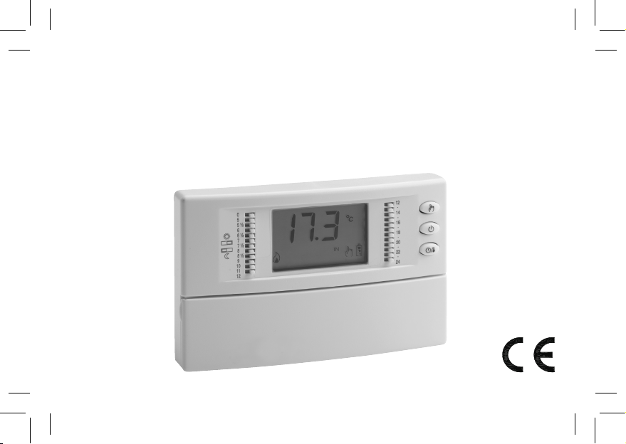
ESBE TP 100 Series User manual
1
CRONOTERMOSTATO DIGITALE A BATTERIE
BATTERY DIGITAL CHRONOSTAT
DIGITALTHERMOSTAT MIT BATTERIEN
CHRONOTHERMOSTAT NUMÉRIQUE ALIMENTÉ PAR BATTERIES
CRONOTERMOSTATO DIGITAL A BATERÍAS
CRONOTERMOSTATO DIGITAL A BATERIAS

2

3
INSTALLAZIONE - INSTALLATION - INSTALLATION - INSTALLATION - INSTALACIÓN - INSTALAÇÃO
Fig. 4 - Abb. 4
Fig. 3 - Abb. 3
Fig. 2 - Abb. 2

4
DESCRIZIONE DEI COMANDI - DESCRIPTION OF CONTROLS -
BESCHREIBUNG DER STEUERUNG - DESCRIPTION DES COMMANDES -
DESCRIPCIÓN DE LOS MANDOS - DESCRIÇÃO DOS COMANDOS
Fig. 1 - Abb. 1
A
G
H
I
F
C
B
L
E
D
M
NN
LEGENDA - LEGEND - LEGENDE - LÉGENDE -
NOTA - LEGENDA
Cavalieri per impostazione modalità comfort/riduzione:
Switches for setting the comfort/economy mode:
Drückrasten für die Einsetzung Modalität Komfort/
Reduzierung:
Cavaliers pour la conguration des modalités
‘Confort’ / ‘Réduction’ :
Jumper para ajuste modalidad Confort/Reducción:
Contactos para conguração das modalidades
conforto/redução:
Intervallo 0 .. 5
Interval 0 .. 5
Zeitabstand 0 .. 5
Intervalle 0 .. 5
Intervalo 0 .. 5
Intervalo 0 .. 5
Intervallo 6 .. 6.30
Interval 6 .. 6.30
Zeitabstand 6 .. 6.30
Intervalle 6 .. 6.30
Intervalo 6 .. 6.30
Intervalo 6 .. 6.30
Intervallo 9 .. 10
Interval 9 .. 10
Zeitabstand 9 .. 10
Intervalle 9 .. 10
Intervalo 9 .. 10
Intervalo 9 .. 10
A

5
Tasto manuale - Manual button - Hand Schalter -
Touche mode manuel - Botón manual - Tecla manual
B
Tasto accensione/spegnimento - On/off button -
Start-Schalter/Stop-Schalter - Touche allumage / extinction -
Botón encendido/apagado - Tecla ligação/desligamento
C
Manopola di riduzione - Economy knob - Reduzierungs-Drehgriff -
Poignée de la modalité Réduction - Mando de reducción -
Manípulo de redução
F
Tasto avanti - Forward button - Schalter vorwärts -
Touche ‘Avant’ - Botón hacia adelante - Teclas de avanço
G
Tasto indietro - Back button - Schalter zurück - Touche Arrière -
Botón hacia atrás - Tecla de retrocesso
H
Tasto Ok - OK button - Ok Schalter - Touche Ok - Botón OK -
Tecla Ok
I
Tasto reset - Reset button - Reset Schalter -
Bouton de réinitialisation - Botón reset - Tecla reset
L
Portabatterie - Battery holder - Batterieträger -
Compartiment des piles - Porta pilas - Porta-baterias
M
Manopola di comfort - Comfort knob - Komfort-Handgriff -
Poignée de la modalité ‘Confort’ - Mando de confort -
Manípulo de conforto
E
Tasto ora/temperatura/programmazione
Time/temperature/programming button
Stunden Schalter/Temperatur Schalter/Programm Schalter
Touche heure / température / programmation
Botón hora/temperatura/programación
Tecla hora/temperatura/programação
D
Sede viti per il ssaggio del corpo del cronotermostato alla
piastra a muro
Screws holes for xing the chronostat body to the wall mount
plate
Löcher zur Befestigung des Chronostat an der Wandhalterung
Position des vis pour la xation du corps du thermostat à la base
de xation murale
Oricios tornillos para la jación del cuerpo del cronotermostato
a la placa a muro.
Parafusos para a xação do corpo do cronotermostato à placa
de montagem de parede
N

6

7
GENERALITÀ
Questo dispositivo è un cronotermostato elettronico giornaliero con
ampio display retroilluminato per la visualizzazione della temperatura
ambiente rilevata o, a scelta, dell’ora corrente.
La regolazione dellla temperatura ambiente in modalità di
Riscaldamento o Raffrescamento avviene su due livelli: Comfort e
Riduzione.
Inoltre il dispositivo offre la possibilità di impostare il valore della
temperatura di Antigelo e la regolazione dell’Offset sul sensore
interno.
INSTALLAZIONE
L’installazione del dispositivo è prevista per il montaggio in scatole
di derivazione da incasso (o da parete) standard da due o tre moduli
oppure direttamente sulla parete utilizzando i tasselli in dotazione.
Per installare il dispositivo eseguire le seguenti operazioni:
- Sganciare la piastra a muro innestata sotto la base del
cronotermostato come indicato in Fig. 2.
- Fissare la piastra direttamente sulla parete o su scatole di derivazione da
3 moduli tramite le due sedi per viti con interasse 60 mm oppure 85 mm
facendo attenzione a fare passare i cavi nella feritoia, come indicato in Fig. 3.
- Eseguire i collegamenti elettrici seguendo lo schema di collegamento
di Fig. 4.
- Avvicinare il cronotermostato alla piastra a muro facendo dapprima
coincidere i dentini della base con gli appositi fori della piastra e
successivamente esercitare sul dispositivo una pressione verso
il basso no a far scattare i dentini plastici della piastra; quindi
ssare il corpo del cronotermostato alla piastra a muro tramite le
due viti in dotazione che trovano sede all’interno del vano portapile
(Fig. 3).
- Inserire le batterie nel vano batterie (M di Fig. 1); vedi paragrafo
‘INSERIMENTO / SOSTITUZIONE BATTERIE’.
Il cronotermostato deve essere posizionato a circa 1,5 m dal
pavimento, lontano da fonti di calore, da porte e nestre.
MESSA IN FUNZIONE
Alla prima messa in funzione:
Inserire le pile rispettando le polarità indicate nell’apposito vano
(Fig. 1) ed eseguire l’operazione di reset agendo con un oggetto
appuntito attraverso l’apposito foro (Ldi Fig. 1). NON USARE AGHI.
I pulsanti presenti sotto lo sportellino inferiore sono 3:
‘OK’: Programmazione/Ora/Conferma (I di Fig. 1);
‘‘: Avanti (G di Fig. 1);
‘’: Indietro (H di Fig. 1);
Regolazione ora corrente
Per regolare l’orologio del cronotermostato eseguire le seguenti
operazioni:
1. Aprire lo sportellino che da’ accesso al vano pile.
2. Premere il pulsante ‘OK’ per almeno 2 secondi.
3. Regolare l’ora con i tasti ‘’ e ‘’.
4. Confermare con ‘OK’.
5. Regolare i minuti con i tasti ‘’ e ‘’
6. Confermare con ‘OK’.
Impostazione Riscaldamento / Raffrescamento
Premendo per almeno 4 secondi il pulsante ‘’ si attiva la funzione
‘Riscaldamento’ e comparirà sul display il simbolo ‘f’ lampeggiante.
ITALIANODEUTSCHFRANÇAISESPAÑOLPORTUGUÊS ENGLISH

8
(Sole), mentre quella di Riduzione viene impostata tramite la manopola
‘‘ (Luna).
Normalmente, per avere una riduzione notturna, la manopola ‘‘ sara’
impostata su un valore inferiore rispetto a quello della manopola ‘‘.
IMPOSTAZIONE PARAMETRI UTENTE
Per entrare nella regolazione dei parametri del cronotermostato,
procedere come segue:
1. Tenere premuto per più di 20 secondi il tasto ‘ ‘; il display
visualizzerà il primo parametro utente ‘ AFr ‘.
2. Premere ripetutamente il tasto ‘ ‘ per scorrere tra i parametri
utente:
Impostazione Antigelo ‘ AFr ’
Impostazione Offset del sensore interno ‘ OFS1 ’
Impostazione Offset della sonda remota ‘ OFS2 ’
Impostazione Sonda di regolazione ‘ rEG ’
Impostazione Differenziale ‘ HYS ’
3. Premere il tasto ‘OK’ per entrare in modica del parametro
selezionato.
3. Congurare i dati relativi ad ogni singolo parametro, come illustrato
nel seguito.
4. Per uscire dalla programmazione dei parametri utente, premere il
tasto ‘o’ confermando le modiche effettuate oppure attendere
10 secondi senza premere alcun tasto.
‘AFr’ IMPOSTAZIONE ANTIGELO
La funzione di Antigelo consente di selezionare una temperatura
minima che viene mantenuta quando il cronotermostato è spento,
in modo tale da preservare l’ambiente e l’impianto qualora la
Premendo invece per almeno 4 secondi il pulsante ‘’, si attiva la
funzione ‘Raffrescamento’ e comparirà sul display il simbolo ‘x’
lampeggiante.
Impostazione modalità Comfort e Riduzione
Il cronotermostato e’ dotato di 24 cavalieri (Adi Fig. 1), posti ai lati
del display per selezionare, durante l’arco della giornata, le fasce di
‘Comfort’ o ‘Riduzione’.
Quando si vuole che il cronotermostato funzioni in modalità di
comfort, per esempio durante le ore diurne, sarà necessario spostare
tutti i cavalieri della fascia oraria desiderata verso destra.
Se invece si desidera che il cronotermostato funzioni in modalità di
riduzione, per esempio durante le ore notturne, basterà spostare tutti
i cavalieri della fascia desiderata verso sinistra.
A questo scopo e’ sufciente ricordare la seguente regola:
Cavalieri posti verso destra: E’ attivata la modalità comfort in
funzionamento automatico.
Cavalieri posti verso sinistra: E’ attivata la modalità di riduzione in
funzionamento automatico.
Ciascun cavaliere si riferisce all’intervallo di tempo compreso tra l’ora
stampata superiormente e quella stampata inferiormente al cavaliere
stesso.
Ad esempio si noti che l’intervallo di tempo dalle 00 alle 05 della
mattina e’ attivato da un unico cavaliere, mentre dalle 05 alle 09
della mattina e’ possibile intervenire di mezz’ora in mezz’ora. Per tutto
il resto della giornata gli intervalli selezionabili sono di un’ora (Adi
Fig. 1).
La temperatura di Comfort viene impostata tramite la manopola ‘‘
ITALIANODEUTSCHFRANÇAISESPAÑOLPORTUGUÊS ENGLISH
9
4. Per uscire premere il tasto ‘o’ oppure attendere 10 secondi senza
premere alcun tasto.
‘OFS2’ IMPOSTAZIONE OFFSET DELLA SONDA REMOTA
Tramite questo parametro è possibile correggere la temperatura
rilevata dalla sonda remota, di ±5°C, in modo da correggere eventuali
errori sistematici di lettura dovuti ad un eventuale posizionamento della
sonda remota in zone inadatte a rilevare la temperatura dell’ambiente.
Il dispositivo esce dalla fabbrica con l’Offset impostato a 0.0°C.
Per regolare la temperatura di Offset della sonda remota eseguire le
seguenti operazioni:
1. Selezionare il parametro ‘ OFS2 ’ e premere il tasto ‘ OK ’.
2. Il display visualizza la temperatura di Offset precedentemente
impostata.
3. Premere i tasti ‘ ’ e ‘ ‘ per modicare il valore (compreso
tra -5.0°C .. +5.0°C); ogni modica viene memorizzata
automaticamente.
4. Per uscire premere il tasto ‘o’ oppure attendere 10 secondi senza
premere alcun tasto.
‘rEG’ IMPOSTAZIONE SONDA DI REGOLAZIONE
Con questo parametro si denisce se la sonda da usare per
la regolazione della temperatura ambiente è quella interna al
cronotermostato oppure quella remota collegata ai morsetti 8 e 9.
Per impostare questo parametro eseguire le seguenti operazioni:
1. Selezionare il parametro ‘ rEG ’ e premere il tasto ‘ OK ’.
2. Il display visualizza ‘ In ‘ oppure ‘ Out ‘.
3. Premere i tasti ‘ ’ e ‘ ‘ per modicare il valore
(In: sensore interno - Out: sonda remota); ogni modica viene
temperatura ambiente scende al di sotto del valore impostato.
Il dispositivo esce dalla fabbrica con l’antigelo impostato a +3°C.
ATTENZIONE: La funzione è attiva solo se il dispositivo è stato
impostato in modalità Riscaldamento.
Per regolare la temperatura di Antigelo eseguire le seguenti operazioni:
1. Selezionare il parametro ‘AFr’ e premere il tasto ‘OK’.
2. Il display visualizza la temperatura di Antigelo precedentemente
impostata.
3. Premere i tasti ‘ ’ e ‘ ‘ per modicare il valore (compreso
tra OFF, 0,5°C..25°C); ogni modica viene memorizzata
automaticamente.
4. Per uscire premere il tasto ‘ o’ oppure attendere 10 secondi senza
premere alcun tasto.
‘OFS1’ IMPOSTAZIONE OFFSET DEL SENSORE INTERNO
Tramite questo parametro è possibile correggere la temperatura
rilevata dal sensore interno, di ±5°C, in modo da correggere eventuali
errori sistematici di lettura dovuti ad un eventuale posizionamento
del cronotermostato in zone inadatte a rilevare la temperatura
dell’ambiente. Il dispositivo esce dalla fabbrica con l’Offset impostato
a 0.0°C.
Per regolare la temperatura di Offset del sensore interno eseguire le
seguenti operazioni:
1. Selezionare il parametro ‘ OFS1 ’ e premere il tasto ‘ OK ’.
2. Il display visualizza la temperatura di Offset precedentemente
impostata.
3. Premere i tasti ‘ ’ e ‘ ‘ per modicare il valore (compreso
tra -5.0°C .. +5.0°C); ogni modica viene memorizzata
automaticamente.
ITALIANODEUTSCHFRANÇAISESPAÑOLPORTUGUÊS ENGLISH

10
sara’ attiva la funzione antigelo e sul display comparirà il simbolo ‘‘;
in tal caso la temperatura ambiente sarà regolata secondo il valore
impostato per la temperatura di antigelo.
FUNZIONAMENTO MANUALE
Premendo il pulsante ‘‘ sul display compare il simbolo ‘‘ ed il
cronotermostato regolerà la temperatura ambiente nell’arco delle
24 ore in modalità di comfort. Ciò signica che la regolazione della
temperatura ambiente avviene, indipendentemente dalla posizione dei
dip switches, secondo la temperatura impostata dalla manopola ‘‘.
Per tornare al funzionamento secondo il programma giornaliero
impostato premere nuovamente il pulsante ‘‘.
VISUALIZZAZIONE ORA / TEMPERATURA
Premendo ciclicamente il pulsante ‘ ‘ si possono visualizzare
sul display alternativamente l’ora corrente, la temperatura ambiente
rilevata dal sensore interno, contradistinta dalla scritta ‘ IN ‘, e la
temperatura ambiente rilevata dalla sonda remota (se collegata)
contradistinta dalla scritta ‘ OUT ‘. Le temperature rilevate vengono
viusualizzate corrette dal valore di Offset impostato.
ATTENZIONE
Le scritte ‘IN’ e ‘OUT’ a seconda di come vengono visualizzate sul
display assumono i seguenti signicati:
‘IN’: Fissa: La temperatura visualizzata è quella rilevata
dal sensore interno, ma la regolazione della
temperatura avviene mediante la sonda
remota.
Lampeggiante: La visualizzazione e la regolazione della
memorizzata automaticamente.
4. Per uscire premere il tasto ‘ o’ oppure attendere 10 secondi senza
premere alcun tasto.
ATTENZIONE: Se la sonda di regolazione è impostata sulla
sonda esterna ‘ Out ‘, in caso di guasto o assenza della sonda, la
regolazione della temperatura verrà automaticamente spostata
sulla sonda interna, pur rimanendo il parametro impostato su
‘ Out ‘.
‘HYS’ IMPOSTAZIONE DIFFERENZIALE
L’impostazione di questo parametro consente di denire l’isteresi, in
°C, che viene applicata al cronotermostato.
ATTENZIONE: La modica di questo parametro deve essere
effettuata da personale qualicato, in quanto un valore
inappropriato può essere causa di funzionamenti anomali.
Per regolare il differenziale eseguire le seguenti operazioni:
1. Selezionare il parametro ‘HYS’ e premere il tasto ‘OK’.
2. Il display visualizza il valore dell’isteresi precedentemente
impostato.
3. Premere i tasti ‘ ’ e ‘ ‘ per modicare il valore
(compreso tra 0.0°C .. 20°C); ogni modica viene memorizzata
automaticamente.
4. Per uscire premere il tasto ‘ o’ oppure attendere 10 secondi senza
premere alcun tasto.
SPEGNIMENTO - FUNZIONE ANTIGELO
Per disattivare il cronotermostato premere il tasto ‘o‘.
Il display mostrera’ la scritta ‘OFF’ ed il simbolo ‘o‘.
Se il cronotermostato e’ stato impostato in modalità di riscaldamento
ITALIANODEUTSCHFRANÇAISESPAÑOLPORTUGUÊS ENGLISH
11
temperatura ambiente avviene mediante
l’utilizzo del sensore interno.
‘OUT’: Fissa: La temperatura visualizzata è quella rilevata
dalla sonda remota, ma la regolazione della
temperatura avviene mediante il sensore
interno.
Lampeggiante: La visualizzazione e la regolazione della
temperatura ambiente avviene mediante
l’utilizzo della sonda remota.
Nel caso in cui il parametro ‘ rEG ‘ sia stato impostato su ‘ Out ‘
ma la sonda remota non è stata collegata o è danneggiata il display
visualizzarà rispettivamente la scritta ‘ SEnS OPEN ‘ oppure
‘ SEnS SHrt ‘ con la scritta ‘ OUT ‘ accesa.
ATTENZIONE: Il cronotermostato, al ne di ottimizzare la durata
delle batterie, rileva la temperatura ambiente ogni 3 minuti e, di
conseguenza, decide l’attivazione o disattivazione del relè.
RETROILLUMINAZIONE
L’accensione della retroilluminazione del display si verica in seguito
alla pressione di un qualsiasi tasto.
Lo spegnimento è automatico dopo 20 secondi dall’ultima pressione
del tasto.
INSERIMENTO / SOSTITUZIONE BATTERIE
Il display mostra costantemente lo stato di carica delle batterie
tramite il simbolo ‘ ‘.
La carica delle batterie è massima se all’interno del simbolo tutti e tre
gli indicatori di livello sono accesi.
Al contrario le batterie sono scariche e devono essere sostituite se
lampeggia il simbolo ‘ ‘ completamente vuoto.
Per la sostituzione procedere come segue:
1. Aprire lo sportellino che da’ accesso al vano pile (Fig. 1).
2. Estrarre le pile eventualmente facendo leva con un utensile.
3. Inserire le nuove pile che devono essere alcaline da 1.5V tipo AA.
4. Eseguire, se necessario, un reset tramite il tasto indicato in Ldi Fig. 1.
5. Controllare l’esattezza dell’ora e, se necessario, riprogrammare
l’ora.
CARATTERISTICHE TECNICHE
Alimentazione: 2 x 1,5V (Tipo AA) alcaline
Durata Batterie: >1 anno
Tempo accensione
retroilluminazione: 20 secondi
Campo di regolazione: comfort: 10°C .. 30°C
ridotta: 10°C .. 30°C
Differenziale: 0.0°C..20.0°C (Default 0.2°C)
Antigelo: 0.0°C .. 25.0°C. (Default 3.0°C)
Offset sensore interno: ± 5.0°C. (Default 0.0°C)
Offset sonda remota: ± 5.0°C. (Default 0.0°C)
Tipo di sensore: NTC 10K Ohm @ 25°C (Interno)
Tipo di sonda remota (opzionale): NTC 10K Ohm ±1% @ 25°C
Precisione: ±1.0°C
Risoluzione: 0.1°C. ( 0.0°C .. 50.0°C)
0.2°C. (-9.9°C .. -0.1°C)
Portata contatti: 5(1)A @ 250V~ SPDT
Grado di protezione: IP 30
ITALIANODEUTSCHFRANÇAISESPAÑOLPORTUGUÊS ENGLISH

12
Tipo di azione: 1
Grado di inquinamento: 2
Categoria di sovratensione: II
Classe di protezione contro
le scosse elettriche: II ( )
Tensione inpulsiva nominale: 2500V
Indice di tracking (PTI): 175
Numero di cicli manuali: 1.000
Numero di cicli automatici: 100.000
Classe del software: A
Tensione prove EMC: 3V
Corrente prove EMC: 38mA
Tolleranza distanza esclusione
modo guasto ‘corto’: ±0,15mm
Temperatura prova sfera: 75°C
Temperatura di funzionamento: 0°C .. +40°C
Temperatura di stoccaggio: -10°C .. +50°C
Limiti di umidità: 20% .. 80% RH non condensante
Contenitore: Materiale: ABS V0 autoestinguente
Colore: Calotta: Bianco segnale (RAL 9003)
Base: Grigio antracite (RAL 7016)
Dimensioni: 133 x 87 x 32 mm. (L x A x P)
Peso: ~ 218 gr.
CLASSIFICAZIONE SECONDO REGOLAMENTO
2013.811.CE
Classe: I
Contributo all’efcienza energetica: 1%
RIFERIMENTI NORMATIVI
Il prodotto è conforme alle seguenti norme (EEC 2004/108/&
2006/95/):
EN-60730-1 (2011)
EN-60730-2-7 (2010)
EN-60730-2-9 (2010)
aATTENZIONE
- Per una corretta regolazione della temperatura ambiente
si consiglia di installare il cronotermostato a circa 1,5 m dal
pavimento e lontano da fonti di calore, correnti d’aria o da pareti
particolarmente fredde (ponti termici).
- E’ obbligatorio, al ne di garantire la sicurezza elettrica, ssare
il corpo del cronotermostato alla piastra a muro tramite le due
viti (in dotazione) che trovano sede all’interno del vano portapile.
- Collegare l’apparecchio alla rete di alimentazione tramite
un interruttore onnipolare conforme alle norme vigenti e con
distanza di apertura dei contatti di almeno 3 mm in ciascun polo.
- L’installazione ed il collegamento elettrico del termostato
devono essere eseguiti da personale qualicato ed in
conformità alle leggi vigenti.
- Prima di effettuare qualsiasi collegamento accertarsi che la
rete elettrica sia scollegata.
GARANZIA
Nell’ottica di un continuo sviluppo dei propri prodotti, il costruttore
si riserva il diritto di apportare modiche a dati tecnici e prestazioni
senza preavviso. Il consumatore è garantito contro i difetti di confor-
mità del prodotto secondo la Direttiva Europea 1999/44/ nonché
il documento sulla politica di garanzia del costruttore. Su richiesta è
disponibile presso il venditore il testo completo della garanzia.
ITALIANODEUTSCHFRANÇAISESPAÑOLPORTUGUÊS ENGLISH

13
paragraph ‘ HOW TO INSERT/REPLACE THE BATTERIES ’.
The chronostat must be positioned about 1.5 m above oor
level, away from sources of heat, doors and windows.
STARTING
When operating the device for the rst time:
Fit the batteries into the compartment provided, observing proper
polarity (Fig. 1). Reset the device by inserting a pointed implement
through the hole provided (L on Fig. 1); DO NOT USE NEEDLES.
There are three control buttons beneath the lower cover 3:
‘OK’: Programming/Time/Conrm (I on Fig. 1);
‘‘: Forward (G on Fig. 1);
‘’: Back (H on Fig. 1);
Setting the current time
To set the timer thermostat clock carry out the following steps:
1. Open the cover of the battery compartment.
2. Press the ‘ OK ’ button for at least 2 seconds.
3. Set the hour using buttons ‘ ‘ and ‘ ‘.
4. Conrm with ‘ OK ’.
5. Set the minutes using buttons ‘ ‘ and ‘ ‘
6. Conrm with ‘ OK ’.
Setting the Heating / Cooling modes
Pressing button ‘ ’ for at least 4 seconds will activate the ‘Heating’
function and the ‘ f ’ symbol will appear ashing on the display.
Pressing button ‘ ’ for at least 4 seconds will instead activate
the ‘Cooling’ function and the ‘ x ’ symbol will appear ashing on
the display.
OVERVIEW
This device is an electronic daily chronostat with an ample backlit
display for showing the room temperature reading or current time,
as desired.
The room temperature can be set in the Heating or Cooling mode on
two different levels: Comfort and Economy.
In addition, the device offers the option of setting the Antifreeze
temperature and adjusting the Offset value on the internal sensor.
INSTALLATION
The device is designed to be installed in a standard recess (or wall)
mounted junction box with two or three modules or else directly on
the wall using the screw anchors provided.
To install the device carry out the following steps:
- Release the wall plate tted under the base of the timer thermostat
as shown in Fig. 2.
- Fix the plate directly to the wall or a 3-module ush connection box
using the two screw fastening holes with centres spaced 60 mm or
85 mm apart (Fig. 3), taking care to thread the wires through the
slot as shown in Fig. 3.
- Make the electrical connections following the connection layout
shown in Fig. 4.
- Bring the timer thermostat near the wall plate, rst matching up
the teeth on the base with the holes in the plate, and then pressing
downward on the device until the plastic teeth snap into place; then x
the chronostat body to the wall mount plate through the two screws
supplied which must be mounted in the battery holder (Fig. 3).
- Insert the batteries in the battery compartment (M in Fig. 1); see
ITALIANODEUTSCHFRANÇAISESPAÑOLPORTUGUÊS ENGLISH
14
as follows:
1. Press for more than 20 seconds the key ‘ ‘; the display will
show the rst user parameter ‘ AFr ‘.
2. Press the ‘ ‘ button repeatedly to scroll through the user
parameters:
Antifreeze Setting ‘ AFr ’
Internal sensor Offset setting ‘ OFS1 ’
Remote sensor Offset setting ‘ OFS2 ’
Regulation sensor choice setting ‘ rEG ’
Hysteresis setting ‘ HYS ’
3. Press the ‘ OK ’ button to modify the selected parameter.
4. Congure the data associated with each individual parameter as
illustrated below.
5. To exit the user parameter programming mode, press the ‘ o’
button to conrm the changes made or else wait 10 seconds
without pressing any button.
‘AFr’ ANTIFREEZE SETTING
The Antifreeze function allows you to select a minimum temperature
to be maintained when the chronostat is off, so as to protect both the
room and the equipment when the room temperature falls below the
set value. The device leaves the factory with the Antifreeze function
set on 3°C.
IMPORTANT: the function is active only when the device has
been set in the heating mode.
To set the Antifreeze temperature, carry out the following steps:
1. Select the parameter ‘ AFr ’ and press the ‘ OK ’ button.
2. The display will show the previously set Antifreeze temperature.
3. Press buttons ‘ ’ and ‘ ‘ to change the setting (between
Setting the Comfort and Economy modes
The timer thermostat has 24 switches (Aon Fig. 1), situated
alongside the display, for programming operation in the ‘Comfort’ or
‘Economy’ modes at different times of the day.
When you want the timer thermostat to operate in the comfort mode,
for example during the daytime, move all the switches corresponding
to the desired time interval over to the right.
If you want the timer thermostat to operate in the economy mode,
for example during the nighttime, just move all of the switches
corresponding to the desired time interval over to the left.
In this case it is sufcient to remember the following rule:
Switches positioned to the right: The comfort setting is enabled in
the automatic operating mode.
Switches positioned to the left: The economy/night setting is
enabled automatic operating mode.
Each switch corresponds to the interval falling between the times
printed above and below the switch itself.
For example, note that the time interval from 00 to 05 is controlled by
a single switch, whereas from 05 to 09 in the morning settings can
be made at half-hour intervals. For the rest of the day, the selectable
time intervals are one hour each (Aon Fig. 1).
The Comfort temperature is set by means of knob ‘ ‘ (Sun), whereas
the Economy temperature is set by means of knob ‘ ‘ (Moon).
Normally, in order to have a reduced temperature at nighttime, knob
‘ ‘ will be set on a lower value than knob ‘ ‘.
SETTING THE USER PARAMETERS
To enter the mode for setting the chronostat parameters, proceed
ITALIANODEUTSCHFRANÇAISESPAÑOLPORTUGUÊS ENGLISH
15
3. Press buttons ‘ ’ and ‘ ‘ to modify the setting (range:
-5.0°C .. +5.0°C); every change will be automatically stored
in memory.
4. Press key ‘ o ’ to quit or wait 10 seconds without pressing any key.
‘rEG’ REGULATION SENSOR CHOICE SETTING
This parameter sets whether the room temperature regulation is
made based on the chronostat internal sensor or the remote sensor,
wired at terminals 8 and 9.
For this parameter setting please nd these directions:
1. Select parameter ‘ rEG ’ then press key ‘ OK ’
2. The display shows ‘ In ‘ or ‘ Out ‘.
3. Press keys ‘ ’ and ‘ ‘ to change the value (In: internal sensor
- Out: remote sensor); each change is automatically stored in memory.
4. Press key ‘ o ’ to quit or wait 10 seconds without pressing any key.
WARNING: When the regulation is set according to the remote
sensor ‘ Out ‘ and in case this sensor is missing or broken, the
temperature regulation will be performed according to the
internal sensor, even if the parameter remains set on ‘ Out ‘.
‘HYS’ HYSTERESIS SETTING
This parameter sets the hysteresis, in °C, used in the temperature
regulation.
WARNING: Setting this parameter must absolutely be made by
qualied personnel because setting an inappropriate value might
result in wrong operation of the whole regulation system.
To set the hysteresis follow these directions:
1. Select the parameter ‘ HYS ’ and press the ‘ OK ’ button.
2. The display shows the hysteresis value previuosly set.
OFF, 0.5°C..25°C); every change will be automatically
memorized.
4. To exit press the ‘ o’ button or else wait 10 seconds without
pressing any button.
‘OFS1’ INTERNAL SENSOR OFFSET SETTING
With this parameter it is possible to correct the temperature reading
of the internal sensor by ±5°C in order to correct any systematic
reading errors due to the positioning of the chronostat in areas
unsuitable for measuring the room temperature. The device leaves
the factory with the Offset set at 0.0°C.
To adjust the Offset value for the internal sensor, carry out the
following steps:
1. Select the ‘ OFS1 ’ parameter and press the ‘ OK ’ button.
2. The display will show the previously set Offset temperature.
3. Press buttons ‘ ’ and ‘ ‘ to modify the setting (range:
-5.0°C .. +5.0°C); every change will be automatically stored
in memory.
4. Press key ‘ o ’ to quit or wait 10 seconds without pressing any key.
‘OFS2’ REMOTE SENSOR OFFSET SETTING
With this parameter it is possible to correct the temperature reading
of the remote sensor by ±5°C in order to correct any systematic
reading errors due to the positioning of the remote sensor in areas
unsuitable for measuring the room temperature. The device leaves the
factory with the Offset set at 0.0°C.
To adjust the Offset value for the internal sensor, carry out the
following steps:
1. Select the ‘ OFS2 ’ parameter and press the ‘ OK ’ button.
2. The display will show the previously set Offset temperature.
ITALIANODEUTSCHFRANÇAISESPAÑOLPORTUGUÊS ENGLISH
16
set Offset value.
WARNING
Labels ‘IN’ and ‘OUT’, according to the way they are displayed,
assume the following different meaning:
‘IN’: Fixed: The temperature shown on the display is the
one measured by the internal sensor, yet the
temperature regulation takes place according to
the remote sensor.
Flashing: Both temperature shown and room temperature
regulation refer to the internal sensor.
‘OUT’: Fixed: The temperature shown on the display is the
one measured by the remote sensor, yet the
temperature regulation takes place according to
the internal sensor.
Flashing: Both temperature shown and room temperature
regulation refer to the remote sensor.
In case the parameter ‘ rEG ‘ is set on ‘ Out ‘ but the remote sensor is
not wired or is broken the display will show the words ‘ SEnS OPEN
‘ or ‘ SEnS SHrt ‘ with the label ‘ OUT ‘ turned on.
IMPORTANT: In order to optimize battery life, the chronostat
reads the room temperature every 3 minutes and activates or
deactivates the relay accordingly.
BACKLIT DISPLAY
The display lights up any time a button is pressed.
The backlight automatically goes off 20 seconds after the last button
was pressed.
3. Press buttons ‘ ’ and ‘ ‘ to change the setting (between
0.0°C..20°C); every change will be automatically memorized.
4. To exit press the ‘ o’ button or else wait 10 seconds without
pressing any button.
SHUTDOWN - ANTI-FREEZE FUNCTION
To switch off the timer thermostat press ‘ o‘.
The display will show the word ‘OFF’ and the ‘ o‘ symbol.
If the timer thermostat was set in the heating mode, the antifreeze
function will be enabled and the ‘ ‘ symbol will appear on the
display; in such a case the room temperature will be controlled
according to the programmed antifreeze temperature set point.
MANUAL OPERATION
Pressing the ‘ ‘ button will cause the ‘ ‘ symbol to appear on the
display and the timer thermostat will control the room temperature
according to the current comfort mode setting selected by means
of knob ‘ ‘, 24 hours a day, irrespective of the position of the
dipswitches.
To revert to operation according to the set daily program, press
‘ ‘ again.
TEMPERATURE / TIME DISPLAY
By repeatedly pressing the key ‘ ‘ the display cycles on showing
the current time, the room temperature measured by the internal
sensor, explained by the label ‘ IN ‘, and the room temperature
measured by the remote sensor (if wired) explained by the label
‘ OUT ‘.
The values of temperature displayed are shown adjusted with the
ITALIANODEUTSCHFRANÇAISESPAÑOLPORTUGUÊS ENGLISH
17
CHANGING THE BATTERIES
The display constantly shows the battery charge status by means
of the ‘ ‘ symbol. Batteries are fully charged if all three battery
level indicators are lit up.
If the symbol is completely empty and ‘ ‘ ashes, it means the
batteries are low and need replacing.
To change the batteries proceed as follows:
1. Open the battery compartment cover (Fig. 1).
2. Remove the spent batteries, prying them out with a tool if necessary.
3. Insert the new batteries, which must be alkaline 1.5V type AA.
4. If necessary reset the device by means of the button as indicated
in Lon Fig. 1.
5. Check that the time setting is correct, reprogram the time if
necessary.
TECHNICAL CHARACTERISTICS
Power supply: 2 x 1.5V alkaline batteries (Type AA)
Battery life: >1 year
Backlight ON time: 20 seconds
Range of settings: comfort: 10°C .. 30°C
economy: 10°C .. 30°C
Differential: 0.0°C..20.0°C (Default 0.2°C)
Antifreeze: 0.0°C .. 25.0°C. (Default 3.0°C)
Offset internal sensor: ± 5.0°C. (Default 0.0°C)
Offset remote probe: ± 5.0°C. (Default 0.0°C)
Sensor type: NTC 10K Ohm @ 25°C (Internal)
Remote probe type (optional): NTC 10K Ohm ±1% @ 25°C
Precision: ±1.0°C
Resolution: 0.1°C. ( 0.0°C .. 50.0°C)
0.2°C. (-9.9°C .. -0.1°C)
Contact capacity: 5(1)A @ 250V~ SPDT
Protection rating: IP 30
Type of action: 1
Pollution degree: 2
Class of protection against
electric shock: II ( )
Rated impulsevoltage: 2500V
Tracking Index (PTI): 175
Number of manual cycles: 1.000
Number of automatic cycles: 100.000
Software class: A
EMC test voltage: 3V
EMC test current: 38mA
ITALIANODEUTSCHFRANÇAISESPAÑOLPORTUGUÊS ENGLISH

18
Distances tolerances fault
mode ‘short’ exclusion: ±0,15mm
Ball pressure test temperature: 75°C
Operating temp.: 0°C .. +40°C
Storage temperature: -10°C .. +50°C
Humidity limits: 20% .. 80% RH non-condensing
Enclosure: Material: ABS V0 self-extinguishing
Colour: Cover: Signal white (RAL 9003)
Base: Anthracite grey (RAL 7016)
Dimensions: 133 x 87 x 32 mm. (W x H x D)
Weight: ~ 218 gr.
CLASSIFICATION UNDER REG. 2013.811.EC
Class: I
Contribution to energy efciency: 1%
NORMATIVE REFERENCES
The product complies with the following standards (EEC 2004/108/EC
and 2006/95/EC):
EN-60730-1 (2011)
EN-60730-2-7 (2010)
EN-60730-2-9 (2010)
aWARNING
- To adjust properly room temperature, install the chronostat
about 1.5 m above oor level and far from heat sources,
airstreams or particularly cold walls (thermal bridges).
- In order to grant the electrical safety, it is mandatory to screw
the chronostat body to the wall mount plate through the two
screws supplied which must be mounted in the battery holder.
- The appliance must be wired to the electric mains through a
switch capable of disconnecting all poles in compliance with
the current safety standards and with a contact separation of
at least 3 mm in all poles.
- Installation and electrical wirings of this appliance must be
made by qualied technicians and in compliance with the
current standards.
- Before wiring the appliance be sure to turn the mains power
off.
WARRANTY
In the view of a constant development of their products, the
manufacturer reserves the right for changing technical data and
features without prior notice. The consumer is guaranteed against
any lack of conformity according to the European Directive
1999/44/EC as well as to the manufacturer’s document about the
warranty policy. The full text of warranty is available on request from
the seller.
ITALIANODEUTSCHFRANÇAISESPAÑOLPORTUGUÊS ENGLISH

19
- Setzen Sie die Batterien in das Batteriefach (siehe M, Fig. 1); lesen Sie
den Abschnitt ‘AUSTAUSCH DER BATTERIEN / BATTERIEWECHSEL’.
Der Chronothermostat muss 1,5 m vom Fußboden entfernt
positioniert werden, weit entfernt von Wärmequellen, von
Türen und Fenstern.
INBETRIEBSETZUNG
Bei der ersten Inbetriebsetzung:
die Batterien einsetzen, beim Respektieren der Polarität, in den dazu
vorgesehen Raum (Abb. 1), und die Reset-Operation ausführen, indem
man mit einem Spitzen-Objekt durch das vorhandene Loch agiert (L
Abb. 1); MAN DARF KEINE NADELN BENUTZEN.
Die vorhandenen Schalter unter der kleinen Tür sind drei:
‘ OK ‘: Programmation/Stunde/Bestätigung (I Abb. 1);
‘ ‘: Vorwärts (G Abb. 1);
‘ ‘: Zurück (H Abb. 1);
Regulierung der laufenden Stunde
Um die Uhr des Chronothermostates zu regulieren folgende
Operationen ausführen:
1. Die kleine Tür öffnen, welche Zutritt zum Batterie-Raum gibt.
2. Den Schalter ‘ OK ‘ für wenigstens zwei Sekunden drücken.
3. Die Stunde mit den Schaltern ‘ ‘ und ‘ ‘ einstellen.
4. Mit ‘ OK ‘ bestätigen.
5. Die Minuten mit den Schaltern ‘ ‘ und ‘ ‘ regulieren.
6. Mit ‘ OK ‘ bestätigen.
Heizung/Einstellung Einstellung der Abkühlung
Beim Drücken für wenigstens 4 Sekunden des Schalters ‘ ‘,
aktiviert sich die Funktion Heizung. Auf dem Display wird das
ALLGEMEINES
Diese Vorrichtung ist ein elektronisches Tages-Thermostat mit
breitem Display, bei hinterer Beleuchtung für die Sichtbarmachung
der festgestellten Umwelt-Temperatur sowie, wahlweise, der
laufenden Stunde. Die Regulierung der Umwelt-Temperatur bei der
Heizung- oder Abkühlungs-Modalität geschieht auf zwei Niveaus:
Komfort und Reduktion. Diese Vorrichtung bietet außerdem die
Möglichkeit, den Wert der einfrierverhütenden-Temperatur sowie der
Offset-Regulierung auf dem Innen-Sensor einzustellen.
INSTALLATION
Das Gerät ist so konstruiert, das es für die Montage direkt
auf der Wand, über Unterputzdosen (2 oder 3-fach), sowie in
Standardverteilern erfolgen kann.
Um die Vorrichtung zu installieren, folgende Operationen ausführen:
- die Wand-Platte, welche unter den Sockel des Chronothermostates
gekuppelt ist, frei machen wie auf Abb. 2 gezeigt.
- Die Platte direkt auf die Wand oder auf eine Abzweige-Schachtel mit
3 Modulen durch die zwei Schrauben-Sitzen fest machen bei einem
Achsabstand von 60 oder 85 mm (Abb. 3), indem man gut aufpasst, dass
die Kabel in die Schlitzscharte frei durchgehen , wie auf Abb. 3 gezeigt.
- Die elektrischen Anschlüsse ausführen, indem man das Verbindungs-
Schema von Abb. 4 befolgt.
- Den Chronothermostat an die Wandplatte näher bringen, indem
man vorher die Verzahnung des Sockels zusammen mit der dazu
vorhandenen Löchern der Platte trifft; hinterher sollte man einen
nach unten gerichteten Druck ausüben, bis die plastischen Zähnchen
der Platte losschnellen; befestigen Sie nun den Regler an der
Wandhalterung und xieren diesen mit den beiliegenden Schrauben
(Batteriefach) siehe Fig. 3.
ITALIANODEUTSCHFRANÇAISESPAÑOLPORTUGUÊS ENGLISH
20
Stunde. (AAbb. 1). Die Komfort-Temperatur wird mit dem Drehgriff
‘ ‘ (Sonne), während diejenige für die Reduzierung mittels des
Drehgriffes ‘ ‘ eingesetzt wird. (Mond). Normalerweise, um eine
Nacht-Reduktion zu erzielen, muss der Drehgriff ‘ ‘ auf einen Wert
eingesetzt sein, der kleiner sein muss als denjenigen des Drehgriffes
‘ ‘.
EINSTELLUNG DER BENUTZERPARAMETER
Um in den Einstellmodus der Betriebsparameter einzusteigen gehen
Sie wie folgt vor:
1. Drücken Sie die Taste ‘ ‘; für mehr als 20 Sekunden, in der
Anzeige erscheint der erste Parameter ‘ AFr ‘.
2. Drücken Sie die ‘ ‘ Taste wiederholt um durch die Parameter
zu scrollen:
Frostschutzeinstellung ‘ AFr ’
Ausgleich der Regelabweichung des internen Fühlers ‘ OFS1 ’
Ausgleich der Regelabweichung des externen Fühlers ‘ OFS2 ’
Auswahl des Regelfühlers ‘ rEG ’
Einstelung Hysterese ‘ HYS ’
3. Drücken Sie die ‘OK’ Taste um den ausgewählten Parameter zu
verändern.
4. Kongurieren Sie die zu jedem Parameter dazugehörigen Daten wie
folgt.
5. Um den Programmiermodus zu verlassen, drücken Sie die ‘ o’
Taste um die Änderungen zu bestätigen, oder warten Sie für 10
Sekunden ohne eine Taste zu drücken.
‘AFr’ FROSTSCHUTZEINSTELLUNG
Die Frostschutzeinstellung erlaubt die Auswahl einer
leuchtende Sinnbild ‘ f‘ erscheinen.
Beim Drücken für wenigstens 4 Sekunden des Schalters ‘ ‘,
aktiviert sich die Funktion Abkühlung und auf dem Display wird das
leuchtende Sinnbild ‘ x‘ erscheinen.
Einsetzung Modalität Komfort und Reduzierung.
Der Chronothermostat ist mit 24 Rasten ausgerüstet (AAbb. 1), welche
sich an beiden Seiten des Displays benden, um während des Tages die
Banden von “Komfort” und “Minderung” auszuwählen.
Wenn man wünscht, dass der Chronothermostat in Modalität Komfort
funktioniert, zum Beispiel während der Tagesstunden, wird es
notwendig sein, alle Rasten der gewünschten Stundes-Banden nach
rechts zu schieben.
Wenn man wünscht, dass der Chronothermostat in Modalität
Reduzierung funktioniert, zum Beispiel während der Nachtstunden,
genügt es alle Rasten der gewünschten Banden nach links zu schieben.
Zu diesem Zweck genügt es sich folgender Norm zu erinnern:
Rasten welche sich rechts benden: es ist die Modalität Komfort
aktiviert, bei automatischer Funktionierung.
Rasten welche sich links benden: es ist die Modalität Nacht-
Reduzierung aktiviert, bei automatischer Funktionierung.
Jede Raste bezieht sich an das Zeit-Intervall welches zwischen der
oben gedrückten Uhrzeit bzw. der unter der betreffenden Raste
gedrückt ist.
Man merke sich als Beispiel, dass die Zeitspanne zwischen
Mittenacht und 05 Uhr morgens, von einer einzigen Raste aktiviert
wird, während von 05 bis 09 Uhr morgens ist es möglich jede Halbe
Stunde einzustellen.
Für den Rest des Tages, die auswählbaren Intervallen betragen je eine
ITALIANODEUTSCHFRANÇAISESPAÑOLPORTUGUÊS ENGLISH
This manual suits for next models
2
Table of contents
Languages:
Other ESBE Thermostat manuals


Popular Thermostat manuals by other brands

Field Controls
Field Controls EvenAir TSRC Installation and user manual

CAME BPT
CAME BPT TH/550 Installation and use manual

Siemens
Siemens Powers TH 188 Technical instructions

Honeywell
Honeywell RTH111 series installation guide

White Rodgers
White Rodgers P150 install guide

White Rodgers
White Rodgers 1F83-261 Installation and operation instructions


