ESBE TFC121 User manual
TFD0420001EV 025641 070815
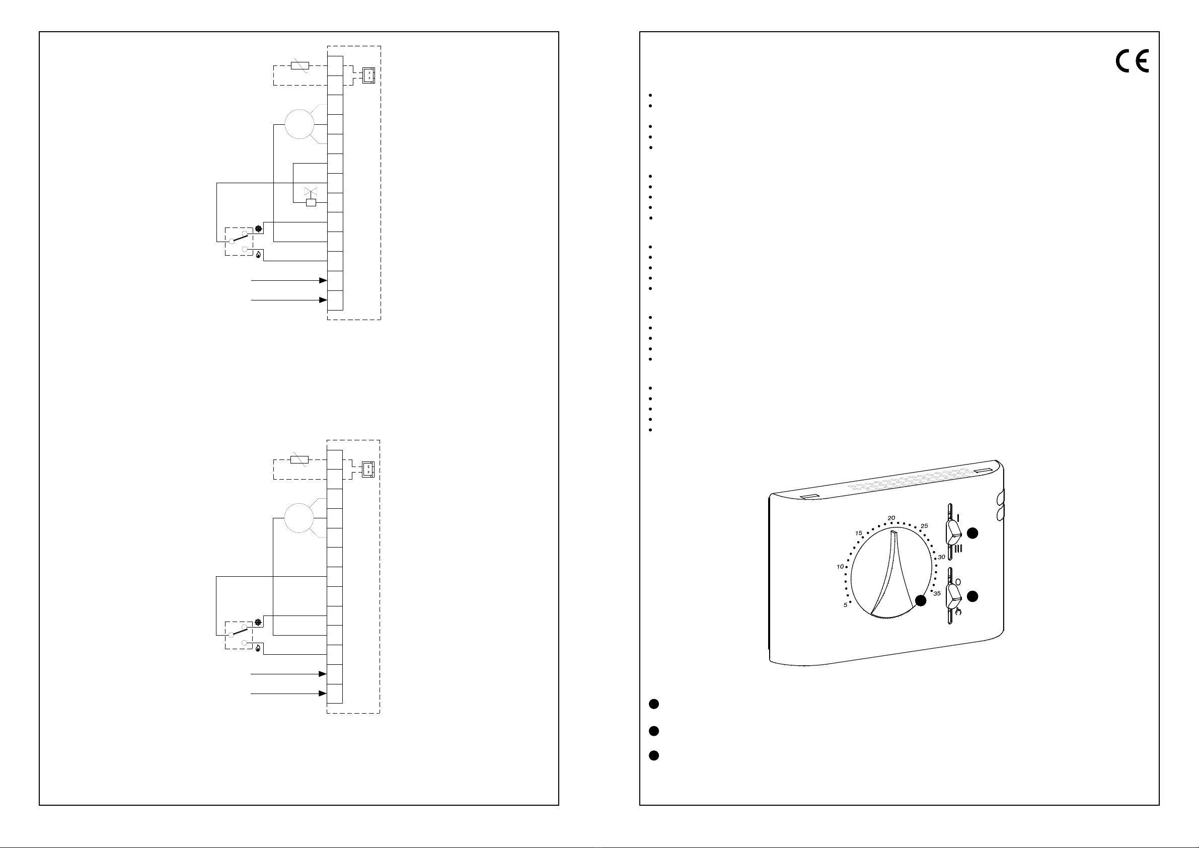
Fig. 14: Esempio di collegamento con commutatore per Raffrescamento (E) / Riscaldamento (I) centralizzato e sensore esterno
opzionale (S.E.).
Wiring example for centralised Cooling (E) / Heating (I) through remote switching, and optional remote sensor (S.E.).
Exemple de connexion avec commutateur pour refroidissement (E) / chauffage (I) centralisé et capteur externe en optino
(S.E.).
Ejemplo de conexión con conmutador para Refrigeración (E) / Calefacción (I) centralizado y sensor externo optional (S.E.).
Abb. 14: Verdrahtungsbeispiel für zentralisiertes Kühlen (E) / Heizen (I) durch Fernumschaltung, Heiz/Kühlventil (E.V.) und
optionaler Fernfühler (S.E.)
Fig. 13: Esempio di collegamento con commutatore per Raffrescamento (E) / Riscaldamento (I) centralizzato, elettrovalvola
caldo / freddo (E.V.) e sensore esterno opzionale (S.E.).
Wiring example for centralised Cooling (E) / Heating (I) through remote switching, heating/cooling electrovalve (E.V.) and
optional remote sensor (S.E.).
Exemple de connexion avec commutateur pour refroidissement (E) / chauffage (I) centralisé, électrovanne chaud/froid
(E.V.) et capteur externe en optino (S.E.).
Ejemplo de conexión con conmutador para Refrigeración (E) / Calefacción (I) centralizado, electroválvula calor / frío
(E.V.) y sensor externo opcional (S.E.).
Abb. 13: Verdrahtungsbeispiel für zentralisiertes Kühlen (E) / Heizen (I) durch Fernumschaltung, Heiz/Kühlventil (E.V.) und
optionaler Fernfühler (S.E.)
4
5
230V~
50/60Hz
N
L
N
L
3
4
II
III
E.V.
COM M~
S.A.
I11
8
6
7
10
9
13
12
S.A.
24V~
5
N
L
3
4
11
8
6
7
10
9
13
12
S.A.
50/60Hz
230V~ N
L
S.A.
M~
III
COM
I
II
24V~
TFD0420001EV 025641 070815
Fig. 1: Aspetto esterno / External aspect / Aspect extérieur / Aspecto externo
Abb. 1: Außenansicht
LEGENDA - LEGEND - LEGENDE - LÉGENDE - NOTA
Selettore velocità motore - Motor speed selector - Wählschalter Ventilatorgeschwindigkeit - Sélecteur de vitesse du moteur -
Selector velocidad motor
Selettore a 3 posizioni: OFF / ON / MANUALE - Three-position selector: OFF / ON / MANUAL - Betriebsartenschalter: kühlen / Aus
(OFF) / heizen - Sélecteur à trois positions: OFF / ON / MANUEL - Selector con tres posiciones: OFF / ON / MANUAL
Manopola regolazione temperatura ambiente - Adjustment Knob room temperature - Drehknopf zur Einstellung des
Raumtemperatur- Sollwertes - Bouton de réglage - Mando giratorio temperatura ambiente
C
A
B
ESBE Series TFC121
TERMOSTATO ELETTRONICO PER VENTILCONVETTORI
Alimentazione 24V~
Funzionamento raffrescamento/riscaldamento centralizzato da
commutatore remoto.
Possibilità di selezione della modalità di funzionamento Off/On/Manuale
Campo di regolazione 5°C .. 35°C
Conforme alle direttive CEE 2004/108 (EMC), 2006/95 (LVD)
ELECTRONIC THERMOSTAT FOR FAN-COILS
24V~ power supply
Heating/cooling function centralised through remote switching
Off/On/Manual operating mode selection
5°C .. 35°C regulation range
In compliance with EEC Directives 2004/108 (EMC), 2006/95 (LVD)
ELEKTRONISCHER THERMOSTAT FÜR GEBLÄSEKONVEKTOREN
Einspeisung 24V~
Heizen/Kühlen Betriebsart durch zentrale Fernumschaltung
Aus/Ein/Manuell Betriebswahlschalter
Einstellbereich 5°C .. 35°C
In Übereinstimmung mit EU Richtlinien 2004/108 (EMC), 2006/95 (LVD)
THERMOSTAT ÉLECTRONIQUE POUR VENTILO-CONVECTEURS
Alimentation 24V~
Fonctionnement centralisé refroidissement/chauffage par commutateur à distance
Possibilité de sélectionner les modalités de fonctionnement Off/On/Manuel
Plage de réglage 5°C .. 35°C
Conforme aux directives CEE 2004/108 (EMC), 2006/95 (LVD)
TERMOSTATO ELECTRONICO PARA FAN COIL
Alimentación 24V~
Funcionamiento refrigeración/calefacción centralizado por un conmutador remoto
Posibilidad de selección de la modalidad de funcionamiento Off/On Manual
Campo de regulación 5°C .. 35°C
Conforme a las directivas CEE 2004/108 (EMC), 2006/95 (LVD)
C B
A
1
TFD0420001EV 025641 070815
2
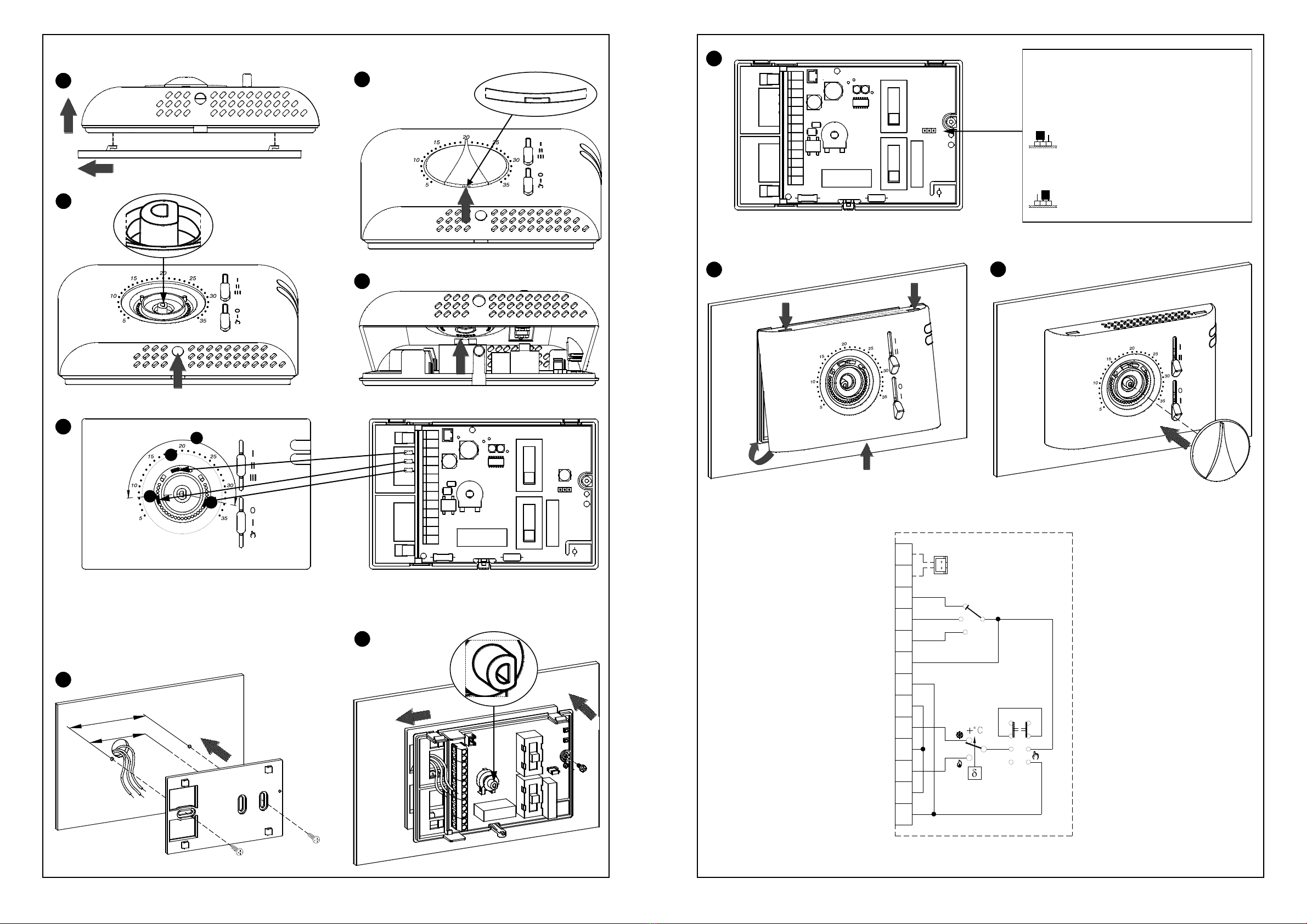
INSTALLAZIONE - INSTALLATION - INSTALLATION - INSTALLATION - INSTALACIÓN
2
1 Fig. 2- Abb. 2
1
Fig. 5- Abb. 5
4
2
1
Fig. 8- Abb. 8
7
Fig. 7- Abb. 7
83mm
60mm
6
2
Fig. 3- Abb. 3
3
Fig. 4- Abb. 4
Fig. 6: Vedere paragrafo "BLOCCO MANOPOLA" a pagina 8 - See the "KNOB LOCK" paragraph on page 9 -
Voir paragraphe " BLOCAGE BOUTON ROTATIF " à la page 11 - Ver el párrafo "BLOQUEO MANDO GIRATORIO" en página 12
Abb. 6: Weitere Informationen zur Funktion "BEGRENZUNG DREHKNOPF" auf Seite 10
5
E
E
F
E
TFD0420001EV 025641 070815
Fig. 10 - Abb. 10
1
3
1
9
2
8
13
11
10
9
8
7
6
12
5
4
3
N
L
A
JP1
B
SA
Fig. 11 - Abb. 11
10
Fig. 12: Schema elettrico interno / Internal diagram / Schéma électrique intérieur / Esquema eléctrico interno
Abb. 12: Innenschaltplan
9
8
7
6
5
3
4
10
11
N
L
O
II
III
I
S.A.
12
13
I
3
Fig. 9- Abb. 9
Sonda a distanza
External sensor
Externer Sensor
Sonde à distance
Sonda a distancia
A
Sonda interna, (impostazione di fabbrica)
Internal sensor, (factory setup)
Interner Sensor, (werkseitige Einstellung)
Sonde interne, (prédisposé par l'usine)
Sonda interna, (ajuste de fábrica)
B
SELEZIONE SONDA INTERNA/ESTERNA
INTERNAL/EXTERNAL SENSOR SELECTION
WAHL FÜR INNEN-/AUßENFÜHLER
SÉLECTION SONDE INTÉRIEURE/EXTÉRIEURE
SELECCIÓN SONDA INTERNA/EXTERNA

GÉNÉRALITÉS
Ce dispositif est un thermostat électronique pour le contrôle de
la température en zones réchauffées ou rafraîchies par ventilo-
convecteurs. L’alimentation est en 24 V~. Le dispositif possède
une entrée pour connecter une sonde de température extérieure
et une pour connecter un commutateur à distance pour la
modalité de chauffage/refroidissement centralisé.
En plus, il est possible de réduire l’angle de rotation de la
molette à travers des cavaliers mécaniques.
INSTALLATION
Pour installer le dispositif, effectuer les opérations suivantes, en
suivant les images indiquées à la page 2 :
Décrocher la plaque fixée sur la base du thermostat en la
poussant vers la gauche et en décrochant ainsi les ergots
indiqués sur la Fig. 2.
Déplacer les deux glissières complètement vers le bas et
placer le bouton rotatif sur 20°C ; soulever ensuite le bouton
rotatif en faisant levier à l'aide d'un tournevis dans la fente
prévue à cet effet et signalée par une flèche sur la Fig. 3, en
faisant attention à ne pas griffer la calotte.
À l'aide d'un tournevis, pousser la languette plastique située dans
la fente en bas jusqu'à soulever légèrement la calotte (Fig. 4).
Tourner la calotte en exerçant une légère pression jusqu'à
l’extraire complètement (Fig. 5).
Prendre les cavaliers mécaniques situés dans la base du
thermostat et les insérer dans la calotte, de façon à réduire le
champ de rotation du bouton rotatif (voir l'exemple sur la Fig. 6
et lire le paragraphe « Blocage bouton rotatif »). Le troisième
cavalier, positionné dans la partie haute, est de réserve.
Fixer la plaque au mur avec deux logements pour vis avec entraxe
60 mm ou bien 85 mm (utiliser les vis et/ou les chevilles en
dotation) en faisant passer les fils par les ouvertures rectangulaires.
-Accrocher la base du thermostat sur la plaque murale (en
faisant passer les fils par les ouvertures rectangulaires) en
faisant d'abord coïncider les trous de la base avec les ergots
prévus à cet effet de la plaque murale ; exercer ensuite sur
la base une pression vers le côté gauche jusqu'au
déclenchement des ergots en plastique de la plaque (Fig. 8).
-Fixer la base du thermostat à la plaque murale en utilisant
les vis en dotation.
-Réaliser les branchements électriques suivant le schéma
de branchement le plus approprié (Fig. 13-14).
-En cas d'utilisation d'une sonde à distance, configurer le
connecteur JP1. Voir le paragraphe « SÉLECTION
SONDE INTERNE / EXTERNE ».
Refermer le thermostat en effectuant les opérations suivantes :
-Positionner les deux ergots de la partie supérieure de la
calotte dans les entailles prévues à cet effet et laisser les
deux glissières en position basse.
-Tourner la calotte en faisant en sorte que les glissières
coïncident avec leurs commutateurs respectifs et pousser
la languette en plastique située sur la partie inférieure de la
base vers le bas (la languette est indiquée par une flèche
sur la Fig. 10) ; exercer une pression jusqu'au
déclenchement de la languette de fixation en plastique à
l'intérieur de l'orifice sur le côté inférieur de la calotte.
Vérifier ensuite que les glissières coulissent correctement.
Positionner le bouton rotatif sur 20°C et l'insérer sur la
calotte.
SÉLECTION SONDE INTÉRIEURE / EXTÉRIEURE
Le thermostat sort de l’usine aménagé pour fonctionner avec
sonde intérieure. Si l'installation prévoit un montage avec sonde à
distance, il faudra déplacer le fil de liaison JP1 (positionné à
droite des sélecteurs sur la plaque interne) en A, comme indiqué
sur la Fig. 9, et brancher au connecteur SA ou bien aux bornes
12 et 13 une sonde du type NTC de 10KΩà 25 °C ayant la valeur
appropriée pour le paramètre bêta. En cas de doutes à propos du
type de sonde à connecter, veiller à consulter le fabricant.
CHAUFFAGE/ REFROIDISSEMENT CENTRALISÉ
Dans le cas où l’installation prévoit le montage de plusieurs
thermostats dans un même édifice, l’entrée centralisée de
chaque thermostat (bornes 3 - 5 - 7) peut être connectées à un
commutateur à distance selon les indications des deux
schémas de connexions proposés (Fig. 13-14), pour l’activation
centralisée des modalités de Chauffage / Refroidissement.
Pour cette modalité, si le commutateur à distance est en position
chauffage, tous les thermostats se mettront automatiquement en
modalité chauffage alors que si le commutateur est en position
refroidissement tous les thermostats se mettront en modalité
refroidissement.
FONCTIONNEMENT
Les commandes du thermostat disponibles pour l’usager sont
deux sélecteurs et un bouton rotatif.
SÉLECTEUR À 3 VITESSES
À l’aide de ce sélecteur à trois positions il est possible de
choisir la vitesse (fixe) d'activation du moteur du convecteur à
ventilation.
SÉLECTEUR OFF / ON / MANUEL
Ce sélecteur a 3 positions ( di Fig. 1), il permet d’activer (en
modalité manuelle ou en modalité Chauffage/Refroidissement
centralisée) ou désactiver le thermostat selon les instructions
ci-dessous :
- Mode Manuel : Positionner le sélecteur sur le symbole : dans
cette position aussi bien le moteur que l'électrovanne (si
celle-ci est prévue) sont toujours actifs, ceci indépendamment
de la température ambiante.
- Mode On : Positionner le sélecteur sur le symbole I: la modalité
de chauffage ou de refroidissement thermostatée est activée
selon la position du commutateur à distance pour l’activation
centralisée des modalités Chauffage / Refroidissement.
- Mode Off : Positionner le sélecteur sur le symbole 0: le
dispositif est éteint.
BOUTON ROTATIF
À l’aide du bouton de réglage il est possible d’établir la
température à partir de laquelle on effectuera le contrôle de la
température désirée, laquelle peut être comprise entre +5° C et
+35 °C.
BLOCAGE DU BOUTON
Il est possible de réduire le champs de réglage du bouton:
1. Extraire le bouton rotatif comme indiqué au point « » du
paragraphe « INSTALLATION ».
2. Positionner les cavaliers mécaniques comme indiqué dans
l'exemple de la Fig. 6 ( ). De cette façon, le champ de rotation
est réduit comme dans l'arc indiqué au point de la Fig. 6.
CARACTÉRISTIQUES TECHNIQUES
Alimentation : 24V~ 50/60 Hz
Puissance absorbée : 1 VA (max)
Capacité des contacts : 5 (1) A @ 250 V~ SPDT
Type de capteur : NTC 10KΩ@ 25 °C ±1% int.
(extérieur en option)
Précision : ±1 °C
Résolution : ±0,5 °C
Plage de réglage : 5 °C / 35 °C
T. de fonctionnement : 0 °C / 40 °C
T. de stockage : -10 ºC / +50 °C
Limites d’humidité : 20 % / 80 % RH (sans condensation)
Degré de protection : IP 30
Conteneur : Matériel : ABS autoextinguible V0
Couleur : Blanc signal (RAL 9003)
Gris clair (RAL 71233)
Dimensions : 132 x 87 x 37 mm (L x H x P)
Poids : ~209 g
CLASSEMENTSELONLE RÈGLEMENT2013.811.EC
Classe: I
Contribution à l’efficacité énergétique: 1%
ATTENTION
- Pour un correct réglage de la température ambiante, il est
conseillé d’installer le thermostat loin de sources de
chaleur, courants d’air ou murs particulièrement froids
(ponts thermiques). Si une sonde à distance est utilisée, la
note doit être appliquée à la sonde et non au thermostat.
- Pour les connexions de la sonde, utiliser des câbles de
section minimum 1,5 mm² et d’une longueur maximum de
25 m. Ne pas faire passer les câbles de la sonde par les
conduites du réseau.
- Brancher l'appareil au réseau d'alimentation à travers un
interrupteur multipolaire conformément aux normes en
vigueur et avec un écartement des contacts d'au moins
3mm à chaque pôle.
- L’installation et la connexion électrique du dispositif
doivent être effectuées par du personnel qualifié et
habilité par les lois en vigueur.
- Avant d’effectuer toute connexion, s’assurer que
l’appareil est débranché du réseau électrique.
GARANTIE
Dans l’optique d’un développement continu de ses produits, le constructeur se réserve
le droit d’apporter sans préavis, des modifications aux données techniques et aux
prestations de ces derniers. Selon la Directive Européenne 1999/44/et le document
qui reporte la politique de garantie du constructeur, le consommateur est protégé contre
les défauts de conformité du produit. Le texte complet de la garantie est disponible
auprès du vendeur sur demande.
TFD0420001EV 025641 070815
1
2
7
4
6
5
3
8
9
10
A
B
2
E
C
F
- FRANÇAIS -
8
FUNZIONAMENTO
I comandi del termostato disponibili per l’utente sono due
selettori ed una manopola.
SELETTORE 3 VELOCITA’
Tramite questo selettore a tre posizioni si può scegliere la
velocità, (fissa), di attivazione del motore del fan-coil.
SELETTORE OFF / ON / MANUALE
Questo selettore a tre posizioni, ( di Fig. 1), permette di attivare
(in modalità manuale o in modalità Riscaldamento/
Raffrescamento centralizzata) o disattivare il termostato, come nel
seguito descritto:
- Modalità Manuale: Posizionare il selettore sul simbolo : in
questa posizione sia il motore che l'elettrovalvola (se prevista)
sono sempre attivati, indipendentemente dalla temperatura
ambiente.
- Modalità On: Posizionare il selettore sul simbolo I: è
attivata la modalità di riscaldamento o raffrescamento
termostatata in base all'impostazione effettuata sul
commutatore remoto per l'attivazione centralizzata delle
modalità di Riscaldamento / Raffrescamento.
- Modalità Off: Posizionare il selettore sul simbolo 0: il
dispositivo è spento.
MANOPOLA
Tramite la manopola di regolazione è possibile impostare la
temperatura attorno a cui verrà effettuato il controllo della
temperatura desiderata che può essere compresa tra +5°C .. +35°C.
BLOCCO MANOPOLA
E' possibile ridurre il campo entro cui ruota la manopola
eseguendo i seguenti passi:
1. Estrarre la manopola come indicato in nel paragrafo
"INSTALLAZIONE".
2. Posizionare i cavalieri meccanici come indicato nell'esempio di
Fig. 6 ( ).
In questo modo il campo di rotazione e' ridotto come
nell'arco indicato in di Fig. 6.
CARATTERISTICHE TECNICHE
Alimentazione: 24V~ 50/60Hz
Potenza assorbita: 1VA (max)
Portata contatti: 5 (1) A @ 250V~ SPDT
Tipo di sensore: NTC 10KΩ@ 25°C ±1% interno
(esterno opzionale)
Precisione: ± 1°C
Risoluzione: 0,5°C
Campo di regolazione: 5°C .. 35°C
Temp. di funzionamento: 0°C .. 40°C
Temp. di stoccaggio: -10°C .. +50°C
Limiti di umidità: 20% .. 80% RH (non condensante)
Grado di protezione: IP 30
Contenitore: Materiale: ABS autoestinguente V0
Colore: Bianco segnale (RAL 9003)
Grigio chiaro (RAL 71233)
Dimensioni: 132 x 87 37 mm (L x A x P)
Peso: ~209 gr.
CLASSIFICAZIONE SECONDO REGOLAMENTO 2013.811.CE
Classe: I
Contributo all’efficienza energetica: 1%
ATTENZIONE
- Per una corretta regolazione della temperatura ambiente
si consiglia di installare il termostato lontano da fonti di
calore, correnti d'aria o da pareti particolarmente fredde
(ponti termici). Se si usa una sonda a distanza la nota va
applicata alla sonda e non al termostato.
- Per i collegamenti della sonda usare cavi di sezione
minima 1,5 mm² e di lunghezza massima di 25 m. Non
passare i cavi della sonda nelle canaline della rete.
- Collegare l'apparecchio alla rete di alimentazione tramite un
interruttore onnipolare conforme alle norme vigenti e con
distanza di apertura dei contatti di almeno 3 mm in ciascun polo.
- L'installazione ed il collegamento elettrico del dispositivo
devono essere eseguiti da personale qualificato ed in
conformità alle leggi vigenti.
- Prima di effettuare qualsiasi collegamento accertarsi che
la rete elettrica sia scollegata.
GARANZIA
Nell'ottica di un continuo sviluppo dei propri prodotti, il costruttore si riserva il
diritto di apportare modifiche a dati tecnici e prestazioni senza preavviso.
Il consumatore è garantito contro i difetti di conformità del prodotto secondo la
Direttiva Europea 1999/44/nonché il documento sulla politica di garanzia
del costruttore. Su richiesta è disponibile presso il venditore il testo completo
della garanzia.
GENERALITÀ
Questo dispositivo è un termostato elettronico per il controllo
della temperatura in ambienti riscaldati o raffrescati da fan-coil
(ventilconvettori). L’alimentazione è a 24V~. Il dispositivo è
predisposto con un’ingresso per collegare una sonda di
temperatura esterna e uno per collegare un commutatore
remoto per la modalità di riscaldamento/raffrescamento
centraliazzato. Tramite dei cavalieri meccanici, è possibile
ridurre l'angolo di rotazione della manopola.
INSTALLAZIONE
Per installare il dispositivo eseguire le seguenti operazioni
seguendo le immagini riportate a pagina 2:
Sganciare la piastra attaccata alla base del termostato
spingendola verso sinistra e facendo cosi' sganciare i dentini
indicati in Fig. 2.
Spostare entrambi gli slider completamente in basso e
posizionare la manopola su 20°C; quindi sollevare la
manopola facendo leva con un cacciavite nell’apposito
invito, indicato dalla freccia in Fig. 3, facendo attenzione a
non rigare la calotta.
Spingere, con l’aiuto di un cacciavite, la linguetta plastica
situata nella feritoia in basso fino a sollevare leggermente la
calotta (Fig. 4).
Ruotare la calotta esercitando una leggera pressione fino ad
estrarla completamente (Fig. 5).
Prelevare i cavalieri meccanici dalla base del termostato ed
inserirli opportunamente nella calotta in modo da ridurre il
campo di rotazione della manopola (vedere l'esempio di
Fig. 6 e leggere il paragrafo 'blocco manopola'). Il terzo
cavaliere parcheggiato in alto è di scorta.
Fissare la piastra alla parete tramite le due sedi per viti con
interasse 60 mm oppure 85 mm (utilizzare le viti e/o i tasselli in
dotazione) facendo passare i fili tramite le aperture rettangolari.
- Agganciare la base del termostato alla piastra a muro
(facendo passare i fili tramite le aperture rettangolari)
facendo dapprima coincidere i fori della base con gli
appositi dentini della piastra a muro e successivamente
esercitare sulla base una pressione verso il lato sinistro
fino a far scattare i dentini plastici della piastra (Fig. 8).
- Fissare la base del termostato alla piastra a muro
utilizzando la vite in dotazione.
- Eseguire i collegamenti elettrici seguendo lo schema di
collegamento più appropriato (Fig. 13-14).
- Se si utilizza una sonda remota, impostare correttamente il
connettore JP1. Vedere il paragrafo 'SELEZIONE SONDA
INTERNA / ESTERNA'.
Richiudere il termostato eseguendo le seguenti operazioni:
- Posizionare i due dentini della parte superiore della calotta
negli appositi intagli e lasciare entrambi gli slider in basso.
- Ruotare la calotta facendo in modo che gli slider
coincidano con i relativi commutatori e spingere verso
l'interno la linguetta plastica posta sulla parte inferiore della
base (indicata dalla freccia in Fig. 10) ed esercitare una
pressione che faccia scattare la linguetta plastica di
fissaggio all'interno del foro sul lato inferiore della
calotta. Quindi verificare la corretta corsa degli slider.
Posizionare la manopola su 20°C ed inserirla sulla calotta.
SELEZIONE SONDA INTERNA / ESTERNA
Il termostato esce dalla fabbrica predisposto per il
funzionamento con sonda interna.
Nel caso in cui l'installazione preveda un montaggio con sonda
a distanza, è necessario spostare il ponticello JP1 in A, come
indicato in Fig. 9, (posizionato sulla scheda interna a destra dei
selettori), e collegare una sonda di tipo NTC da 10KΩa 25°C
con adeguato valore per il parametro beta al connettore SA
oppure in alternativa ai morsetti 12 e 13. In caso di dubbio sul
tipo di sonda da collegare si prega di consultare il costruttore.
RISCALDAMENTO/RAFFRESCAMENTO CENTRALIZZATO
Nel caso in cui l'installazione preveda il montaggio di più
termostati in uno stesso edificio, l'ingresso centralizzato di ogni
termostato (morsetti 3 - 5 - 7) può essere collegato ad un
commutatore remoto, come indicato nei due schemi di
collegamento proposti (Fig. 13-14), per l'attivazione
centralizzata delle modalità di Riscaldamento / Raffrescamento.
In questa modalità, se il commutatore remoto viene impostato su
riscaldamento tutti i termostati saranno settati in riscaldamento,
mentre se il commutatore viene impostato su raffrescamento tutti
i termostati saranno settati in rafrescamento.
TFD0420001EV 025641 070815
1
2
7
4
6
5
3
8
9
10
A
B
2
E
C
F
- ITALIANO -
5

3-SPEEDS SELECTOR
Through this three-position slide selector the user can
choose the (fixed) speed of the fan-coil motor.
OFF / ON / MANUAL SELECTOR
This three-position selector ( in Fig. 1), has the purpose to
operate (either in manual mode or in centralised Heating/Cooling
mode) or stop the thermostat, as described in the following:
- Manual Mode: Set the slider to the position with the
symbol : in this position both the motor and the
electrovalve (when connected) are always powered
regardless of the room temperature.
- On Mode: Set the slider to the position with the symbol I:
controlled Heating or Cooling mode is enabled, according to
the selection made on the remote Heating/Cooling selector.
- Off Mode: Set the slider to the position with the symbol 0: the
thermostat is turned off.
KNOB
Through the temperature set-point knob the user can set the
temperature desired in the room, according to which the
regulation will be performed, in the range +5°C .. +35°C.
KNOB ROTATION LIMITATION
It is possible to limit the rotation range for the set-poin knob by
following these steps:
1. Extract the knob as indicated in " " in the "INSTALLATION"
paragraph.
2. Position the mechanical pins as shown in the example in Fig. 6
( ). The field of rotation is, in this way, reduced as in the arc
shown in in Fig. 6.
TECHNICAL FEATURES
Power supply: 24V~ 50/60Hz
Power absorption: 1VA (max.)
Contact rating: 5 (1) A @ 250V~ SPDT
Sensor type: NTC 10KΩ@ 25°C ±1% internal
(remote optional)
Accuracy: ± 1°C
Resolution: 0,5°C
Regulation range: 5°C .. 35°C
Operating temperature: 0°C .. 40°C
Storage temperature: -10°C .. +50°C
Humidity limits: 20% .. 80% RH (non condensing)
Protection grade: IP 30
Case: Material: ABS self-extinguishing V0
Color: Signal white (RAL 9003)
Light grey
Size: 132 x 87 x 37 mm (W x H x D)
Weight: ~209 gr.
CLASSIFICATION UNDER REGULATION 2013.811.EC
Class: I
Contribution to energy efficiency: 1%
WARNING
- To adjust properly room temperature, install the
thermostat far from heat sources, airstreams or
particularly cold walls (thermal bridges). When the remote
sensor is used in conjunction with the thermostat, then
this note must be applied to the remote sensor itself.
- For remote versions all wirings must be made using wires
with 1,5 mm² minimum cross section and not longer than
25 m. Do not use same duct for signal wires and mains.
- The appliance must be wired to the electric mains through
a switch capable of disconnecting all poles in compliance
with the current safety standards and with a contact
separation of at least 3 mm in all poles.
- Installation and electrical wirings of this appliance must
be made by qualified technicians and in compliance with
the current standards.
- Before wiring the appliance be sure to turn the mains
power off.
WARRANTY
In the view of a constant development of their products, the manufacturer
reserves the right for changing technical data and features without prior
notice. The consumer is guaranteed against any lack of conformity according
to the European Directive 1999/44/EC as well as to the manufacturer’s
document about the warranty policy. The full text of warranty is available on
request from the seller.
OVERVIEW
This device is a thermostat intended for temperature regulation
in environments heated or cooled with fan-coil units. Power
supply is 24V~.
The device features an input to connect an external temperature
probe and another to connect a switch for the remote Heating/
Cooling selection.
By means of the mechanical pins the angle of rotation of the
knob can be reduced.
INSTALLATION
Carry out the operations below to install the device, while
following the images on page 2:
Release the plate attached to the thermostat base by
pushing it to the left. This releases the teeth shown in Fig. 2.
Move both sliders all the way down and position the knob at
20°C; lift the knob using a screwdriver as shown by the
arrow in Fig. 3, being careful not to scratch the cover.
Push the plastic tab in the lower slot using a screwdriver,
slightly lifting the cover (Fig. 4).
Turn the cover, while pressing it slightly, until it is fully
extracted (Fig. 5).
Remove the mechanical pins from the thermostat base and
insert them in the cover to reduce the knob's field of rotation
(see example in Fig. 6 and read the "knob lock" paragraph).
The third pin at the top is a spare.
Fix the plate to the wall, using the two screw seats with centre
distances of 60 mm or 85 mm (use the supplied wall plugs
and/or screws). Pass the wires through the rectangular
openings.
-Connect the thermostat base to the wall plate (pass the
wires through the rectangular openings). Align the base
holes with the special wall plate teeth, then press the base
to the left until the plate's plastic teeth click (Fig. 8).
-Fix the thermostat base to the wall with the supplied
screws.
-Make the electrical connections following the most
appropriate connection diagram (Fig. 13-14).
-Correctly set the connector JP1 if using a remote sensor.
See the "INTERNAL/EXTERNAL SENSOR SELECTION"
paragraph.
Perform the following operations to reclose the thermostat:
-Position the two teeth from the top of the cover into the
specific slots and leave both sliders at the bottom.
-Turn the cover making sure the sliders coincide with the
relative switches, push the plastic tab on the lower part of
the base inwardly (see the arrow in Fig. 10) and press it
so that the plastic fixing tab inside the special hole, at the
bottom of the cover, clicks. Check the sliders' correct
stroke.
Position the knob at 20°C and insert it on the cover.
INTERNAL / EXTERNAL SENSOR SELECTION
The thermostat leaves the factory already set for an internal
sensor work.
In those installations where a remote sensor is required, please
move jumper JP1 (located on the electronic board on the right
side of the selctors) into position A, as shown in Fig. 9, then
wire a 10KΩ@ 25°C NTC sensor with a proper 'Beta' value at
connector SA or, as an alternative, at terminals 12 and 13.
In case of doubts about the sensor to be connected, please ask
the producer.
REMOTE HEATING/COOLING SELECTION
When the system architecture is equipped with several
thermostats in the same building, the relevant inputs of any
thermostats (terminals 3 - 5 - 7) can be connected to a remote
switch for the Heating/Cooling selection, as shown in in the
proposed two diagrams (Fig. 13-14).
Therefore when the remote selector will be set in Heating then all
thermostats will be operated in heating mode, being the opposite
for Cooling mode.
OPERATION
The controls available on the front cover of the thermostat for
the user are two sliders and one knob.
TFD0420001EV 025641 070815
1
2
7
4
6
5
3
8
9
10
A
B
2
E
C
F
- ENGLISH -
6
- DEUTSCH -
7
ALLGEMEINE BESCHREIBUNG
Bei diesem Gerät handelt es sich um einen elektronischen
Thermostat zur Temperaturregelung von Räumen, die mittels
Gebläsekonvektor geheizt oder gekühlt werden.
Die Betriebsspannung beträgt 24V~. Das Gerät verfügt über
einen Eingang um einen externen Temperaturfühler und einen
anderen um einen Fern-Heizen/Kühlen Schalter anzuschließen.
Mit Hilfe der Einstellklemmen begrenzen Sie den Drehwinkel
des Drehknopfes (Einstellung Raumtemperatur-Sollwert).
MONTAGE
Zur Montage / Installation führen Sie die nachfolgenden Schritte
durch. Folgen Sie dabei den Abbildungen auf Seite 2:
Lösen Sie den Raumthermostat von der Wandhalterung, wie
in Abb.2 dargestellt.
Schieben Sie die Wahlschalter nach Unten und den
Drehknopf auf 20°C. Jetzt entfernen Sie den Drehknopf mit
einen Schreubendreher, wie in Abb. 3 dargestellt.
Drücken Sie mit einem Schraubendreher die runde
Kunststofflasche nach hinten (Abb. 4) und lösen den
Gehäusedeckel.
Drehen Sie nun den Deckel nach oben, um diesen
vollständig zu entfernen (Abb. 5).
Entnehmen Sie die Pins aus dem Gehäuseunterteil und
stecken diese in den Deckel um den Drehbereich des
Drehknopfes zu begrenzen (siehe Abb. 6 und Abschnitt
„BEGRENZUNG DREHKNOPF“). Der dritte Pin ist ein
Ersatzteil (zusätzlich).
Befestigen Sie die Wandhalterung mit den beiliegenden
Schrauben (im Abstand 60 oder 85 mm). Führen Sie die
Anschlussleitungen, wie dargestellt, durch die
Wandhalterung (Abb. 7).
- Befestigen Sie den Thermostat auf der Wandhalterung.
Führen Sie die Anschlussleitungen durch die Öffnungen.
Richten Sie den Thermostaten aus und schieben diesen
nach links, bis er einrastet (Abb. 8).
- Sichern Sie den Thermostat mit den beiliegenden
Schrauben auf der Wandhalterung.
- Machen Sie die elektrischen Anschlüsse indem Sie das meist
verwendete Anschlussdiagramm befolgen. (Fig. 13-14).
- Überprüfen Sie die Jumper-Einstellung J1 - externer
Raumtemperaturfühler. Weitere Informationen erhalten sie
im Abschnitt "AUSWAHL RAUMTEMPERATURFÜHLER".
Zum Verschließen des Thermostaten führen Sie
nachfolgenden Schritte durch:
- Setzen Sie nun die Abdeckung wieder auf das Unterteil.
Obere Haken im Deckel einrasten (siehe Abb. 7).
- Vor dem nach unten führen prüfen Sie die Stellung der
Wahlschalter (siehe Abb. 10).
Stecken Sie den Drehknopf (in Position 20°C) auf den Stift.
AUSWAHL RAUMTEMPERATURFÜHLER
Der Thermostat wird mit internem Fühler zur Messung der
Raumtemperatur geliefert. Es besteht die Möglichkeit einen
externen Raumfühler anzuschließen.
Falls Sie einen externen Raumfühler verwenden muss der
Jumper JP1 (auf der Leiterplatte an der rechten Seite) auf die
Position A umgesteckt werden, wie in Fig. 9 dargestellt.
Schließen Sie dann einen NTC Sensor mit folgenden kenn-
Werten: 10KΩ@ 25°C am Anschluss SA bzw. an den Klemmen
12 und 13 an. Bei Fragen zum Fühlertyp, wenden Sie sich an
den Hersteller oder Distributor.
ZENTRALISIERTE UMSCHALTUNG HEIZEN/KÜHLEN
Wenn die Systemarchitektur mit mehreren Thermostate im
gleichen Gebäude ausgerüstet ist, können die relevanten
Eingänge irgendeines Thermostaten (Klemmen 3-5-7) wie in
den vorgeschlagenen Diagrammen (Fig. 13-14) an den
externen Heizen/Kühlen-Schalter angeklemmt warden.
Wenn der Fern-Wahlschalter in der Heizstellung steht, dann
arbeiten alle Thermostaten im Heizbetrieb, und umgekehrt im
Kühlbetrieb.
BEDIENUNG
Bedienung und Einstellung erfolgt mit Hilfe von Schaltern und
über einen Drehknopf.
VENTILATOR-SCHALTER, 3–STUFIG
Über diesen Dreistellungs- Wahlschalter ( , Abb. 1) wird die
(feste) Drehzahl desGebläsekonvektormotors gewählt.
TFD0420001EV 025641 070815
1
2
7
4
6
5
3
8
9
10
AUS / EIN / MANUELL SCHALTER
Der Dreistellungswahlschalter ( in Fig. 1) hat den Zweck den
Thermostat wie folgend beschrieben, in Funktion zu halten
(entweder in manuellem Modus oder in zentralisiertem Heizen/
Kühlen Modus) oder diesen auszuschalten.
- Stellung Manuell: Stellen Sie den Schalter auf die Stellung mit
dem Symbol : In dieser Stellung sind beide, der Lüftermotor
und das Regelventil (sofern vorhanden) unabhängig von der
Raumtemperatur unter Spannung.
- Stellung Ein: Schieben Sie den Schalter mit dem Symbol
I: Heizung oder Kühlung ist gemäß der Wahl des Fern-
Heizen/Kühlen-Schlaters durch den Thermostaten
freigegeben.
- Stellung Aus: Stellen Sie den Schalter auf die Stellung mit
dem Symbol 0: Der Thermostat ist ausgeschaltet.
Drehknopf
Über den Stellknopf ( , Abb. 1) wird die Temperaturje nach
dem gewünschten Bereich, der zwischen +5°C und +35°C liegt,
eingestellt.
BEGRENZUNG STELLBEREICH DREHKNOPF
Es ist möglich den Stellbereich für den Drehknopf zu begrenzen
und somit den einstellbaren Sollwert der Raumtemperatur.
Gehen Sie dazu wie folgt vor:
1. Lösen Sie den Drehknopf, wie erläutert in " " Im Abschnitt
"INSTALLATION".
2. Positionieren Sie die Pins, wie gezeigt im Beispiel ( , Abb.
6). Mit Hilfe der Pins schränken Sie den Drehwinkel des
Knopfes ein ( , Abb. 6).
TECHNISCHE DATEN
Betriebsspannung: 24V~ 50/60Hz
Leistungsaufnahme: 1VA (max)
Schaltleistung: 5 (1) A @ 250V~ SPDT
Sensortyp: NTC 10KΩ@ 25°C ±1%
(eingebauter Fühler oder
externer Fühler)
Einstellbereich: 5°C .. 35°C
Genauigkeit: ± 1°C
Auflösung: 0,5°C
Betriebstemperatur: 0°C .. 40°C
Lagertemperatur: -10°C .. +50°C
Umgebungsfeuchte: 20% .. 80% RH
(nicht kondensierend)
Schutzart: IP 30
Gehäuse: Material: ABS selbstlöschend V0
Farbe: Signalweiß (RAL 9003)
Hellgrau (RAL 71233)
Abmessung: 132 x 87 x 37 mm (L x A x P)
Gewicht: ~209 gr.
KLASSIFIZIERUNG NACH REG. 2013.811.EC
Klasse: I
Energieeffizienz: 1%
ACHTUNG
- Für die korrekte Regulierung der Raumtemperatur
empfiehlt es sich, den Thermostat weit von Wärmequellen,
Zuglüften oder besonders kalten Wänden (Thermobrücke)
aufzustellen. Falls ein Außenfühler benutzt wird, bezieht
sich die Anmerkung auf den Fühler, nicht auf den
Thermostat.
- Für die Anschlüsse des Fühlers benutzen Sie Kabel mit
einem Minimalquerschnitt von 1.5 mm² und einer
Maximallänge von 25 m. Die Kabel des Fühlers sollen auf
keinen Fall in den Kanälen der Leitung gestreckt werden.
- Schließen Sie das Gerät über einem den gültigen Normen
entsprechenden allpoligen Schalter an das
Versorgungsnetz an, die Öffnung dessen Kontakte einen
Abstand von mindestens 3 mm in jedem Pol haben soll.
- Die Installation sowie der Elektroanschluss des Geräts
soll durch qualifiziertes Fachpersonal in Übereinstimmung
mit den geltenden Gesetzen vorgenommen werden.
- Bevor Anschlüsse durchzuführen, sicherstellen, dass das
elektrische Netz ausgeschaltet ist.
GARANTIE
Unter dem Gesichtspunkt einer kontinuierlichen Entwicklung seiner Produkte
behält sich der Hersteller das Recht vor, Veränderungen an den technischen
Daten bzw. Leistungen ohne Kündigung vorzunehmen.
Dem Verbraucher wird eine Produkt-Mängelgewähr nach der EU-Richtlinie
1999/44/sowie dem Dokument über die Garantiepolitik des Herstellers
geleistet.
B
2
E
F
C
A
www.esbe.eu
GENERALIDADES
Este dispositivo es un termostato electrónico para el control de la
temperatura en ambientes calefaccionados o acondicionados por
fan-coil (ventiloconvectores). La alimentación es a 24V~. El
dispositivo está predispuesto con un ingreso para conectar una
sonda de temperatura externa y otro para conectar un conmutador
remoto para la modalidad de calefacción/refrigeración
centralizada. Mediante interruptores de corredera mecánicos, es
posible reducir el ángulo de rotación del mando giratorio.
INSTALACION
Para instalar el dispositivo realizar las siguientes operaciones
siguiendo las imágines de página 2:
Desenganchar la plancha pegada a la base del termostato
empujándola hacia la izquierda haciendo que los dientecillos
plásticos indicados en Fig. 2 se desenganchen.
Mover completamente ambos slider hacia abajo y posicionar
el mando giratorio en 20°C; a este punto levantar el mando
haciendo palanca con un destornillador en la ranura
pertinente, indicado por la flecha en Fig. 3, prestando
atención a no rayar la tapa.
Empujar, con la ayuda de un destornillador, la lengüeta de
plástica situada en la rejilla de la parte inferior hasta levantar
levemente la tapa (Fig. 4).
Girar la tapa ejercitando una ligera presión hasta extraerla
completamente Fig. 5).
Quitar los interruptores de corredera mecánicos de la base
del termostato e inserirlos oportunamente en la tapa para
reducir el campo de rotación del mando giratorio (ver el
ejemplo de Fig. 6 y leer el párrafo "bloqueo mando"). El
tercer interruptor de corredera ubicado en la parte superior
es de repuesto.
Fijar la plancha a la pared mediante los dos orificios para
tornillos con una distancia entre ejes de 60 mm o bien 85 mm
(utilizar los tornillos y/o tacos en dotación) haciendo pasar los
cables por las aberturas rectangulares.
- Enganchar la base del termostato a la plancha a muro
(haciendo pasar los cables por las aberturas rectangulares)
haciendo desde el principio coincidir los orificios de la base con
los dientecillos de la plancha a muro y sucesivamente ejercitar
en la base una presión hacia el lado izquierdo haciendo que
los dientecillos hagan clic en la plancha (Fig. 8).
- Fijar la base del termostato a la plancha a muro utilizando
los tornillos en dotación.
- Realizar las conexiones eléctricas siguiendo el esquema de
conexión más apropiado (Fig. 13-14).
- Si se utiliza una sonda remota, ajustar correctamente el
conector JP1. Ver el párrafo "SELECCIÓN SONDA
INTERNA / EXTERNA".
Cerrar el termostato realizando las siguientes operaciones:
- Posicionar los dos dientecillos de la parte superior de la tapa
en las ranuras pertinentes y dejar ambos interruptores a
corredera hacia abajo.
- Girar la tapa haciendo que los interruptores a corredera
coincidan con los relativos conmutadores y empujar hacia
el interno la lengüeta de plástico ubicada en la parte
inferior de la base (indicada por la flecha en Fig. 10) en
este punto ejercitar una presión que haga enganchar la
misma al interno del orificio ubicado en el costado inferior
de la tapa. A este punto verificar la correcta posición de los
interruptores a corredera.
Posicionar el mando giratorio en 20°C e inserirlo en la tapa.
SELECCION SONDA INTERNA/EXTERNA
El termostato sale de fábrica predispuesto para el funcionamiento
con una sonda interna. Si la instalación prevé montaje con sonda
a distancia, es necesario ubicar el puente JP1 en A, como
indica la Fig. 9, (posicionado en la tarjeta interna a la derecha de
los selectores) y conectar una sonda de tipo NTC de 10KΩa
25° C con adecuado valor para el parámetro beta al conector SA
o bien en alternativa a los bornes 12 y 13. Si hay dudas sobre el
tipo de sonda a instalar, rogamos consultar el constructor.
CALEFACCIÓN / REFRIGERACIÓN CENTRALIZADA
Si la instalación prevé el montaje de más de un termostato en un
mismo edificio, el ingreso centralizado (bornes 3 - 5 - 7) puede
conectarse a un conmutador remoto, como se indica en los dos
esquemas de conexión propuestos en (Fig. 13-14), para la
activación centralizada de las modalidades de Calefacción/
Refrigeración. En esta modalidad, si el conmutador remoto se
ajusta en calefacción todos los termostatos serán posicionados en
calefacción, en cambio si el conmutador se ajusta en refrigeración
todos los termostatos serán posicionados en refrescamiento.
FUNCIONAMIENTO
Los mandos del termostato disponibles para el usuario son dos
selectores y un mando giratorio.
SELECTOR 3 VELOCIDADES
Mediante este selector a tres posiciones se puede elegir la
velocidad, (fija), de activación del motor del fan coil.
Selector OFF/ON/MANUAL
Este selector tiene tres posiciones, ( de Fig. 1), permite activar
(en modalidad manual o en modalidad Calefacción/Refrigeración
centralizada) o desactivar el termostato, como se describe a
continuación:
- Modalidad Manual: Posicionar el selector en el símbolo : en
esta posición el motor como así también la electroválvula (si
prevista) están siempre activas independientemente de la
temperatura ambiente.
- Modalidad On: Posicionar el selector en el símbolo I: Está
activada la modalidad de calefacción o de refrigeración
controlada por termostato en base al ajuste efectuado en el
conmutador remoto para la activación centralizada de la
modalidad de Calefacción/Refrigeración.
- Modalidad Off: Posicionar el selector en el símbolo 0: el
dispositivo está apagado.
MANDO GIRATORIO
Mediante el mando de regulación es posible ajustar la temperatura
en torno a la cual se efectuará el control de la temperatura deseada
que puede ser comprendida entre +5°C .. +35°C.
BLOQUEO MANDO
Es posible reducir el campo en el que rueda el mando siguiendo
los siguientes pasos:
1. Extraer el mando giratorio como se indica en " " del párrafo
"INSTALACIÓN".
2. Posicionar los interruptores de corredera como se indica en el
ejemplo de Fig. 6 ( ). De este modo el campo de rotación
estará reducido como en el arco indicado en de Fig. 6.
CARACTERISTICAS TECNICAS
Alimentación: 24V~ 50/60Hz
Potencia absorbida: 1VA (max)
Capacidad contactos: 5 (1) A @ 250V~ SPDT
Tipo de sensor: NTC 10KΩ@ 25°C ±1% int.
(externo opcional)
Precisión: ± 1°C
Resolución: ± 0.5°C
Campo de regulación: 5°C .. 35°C
Temp. de funcionamiento: 0°C .. 40°C
Temp. de almacenaje: -10°C .. +50°C
Límite de humedad: 20% .. 80% RH (no condensable)
Grado de protección: IP 30
Caja: Material: ABS autoestinguible V0
Color: Blanco (RAL 9003)
Gris claro (RAL 71233)
Dimensiones: 132 x 87 x 37 mm (A x H x P)
Peso: ~209 gr.
CLASIFICACIÓN SEGÚN EL REGLAMENTO 2013.811.EC
Calse: I
Contribución a la eficiencia energética: 1%
ATENCION
- Para una correcta regulación de la temperatura ambiente
se aconseja instalar el termostato lejos de fuentes de
calor, corrientes de aire o de paredes particularmente
frías (puentes térmicos). Si se usa una sonda a distancia
la nota anterior se aplica a la sonda y no al termostato.
- Para la conexión de la sonda usar cables de sección
mínima 1,5 mm² y longitud máx. de 25 m. No pasar los
cables de la sonda en las canaletas de la red eléctrica.
- Conectar el aparato a la red de alimentación mediante un
interruptor omnipolar conforme a las leyes vigentes y con
una distancia de apertura de los contactos de al menos
3 mm en cada uno de los polos.
- La instalación y la conexión eléctrica deben ser realizadas
por personas cualificadas y en conformidad con las leyes
vigentes.
- Antes de efectuar cualquier conexión asegúrese que la
red eléctrica esté desconectada.
GARANTIA
En la óptica de un continuo desarrollo de los propios productos, el fabricante, se
reserva el derecho de aportar modificaciones a los datos técnicos y prestaciones sin
previo aviso. El consumidor está garantizado contra la falta de conformidad del
producto según la Directiva Europea 1999/44/y también por el documento sobre
la política de garantía del constructor. A pedido del cliente está disponible en el
negocio vendedor el texto completo de la garantía.
TFD0420001EV 025641 070815
1
2
7
4
6
5
3
8
9
10
A
B
2
E
C
F
- ESPAÑOL -
9

Other ESBE Thermostat manuals


