ESCO Technologies ETS-Lindgren 3126 Series User manual
Other ESCO Technologies Antenna manuals
ESCO Technologies
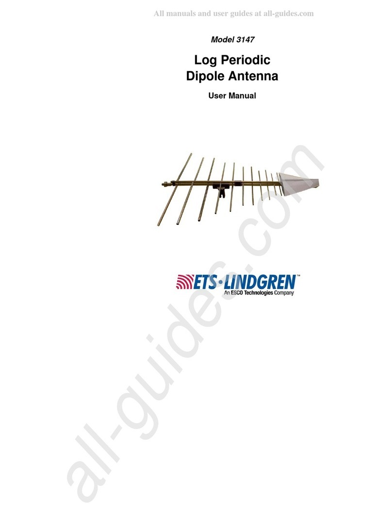
ESCO Technologies ETS Lindgren 3147 User manual
ESCO Technologies
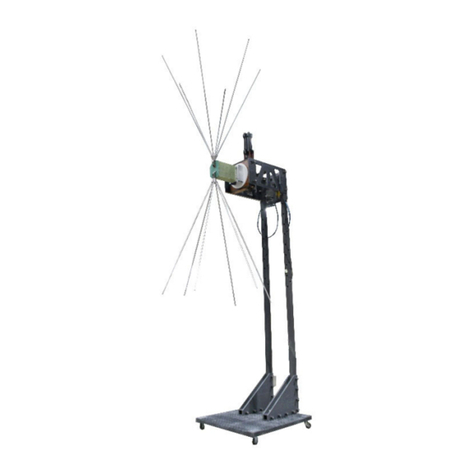
ESCO Technologies ETS-LINDGREN 3159C User manual

ESCO Technologies
ESCO Technologies 3126C Series User manual

ESCO Technologies
ESCO Technologies ETS-Lindgren 3112 User manual
ESCO Technologies
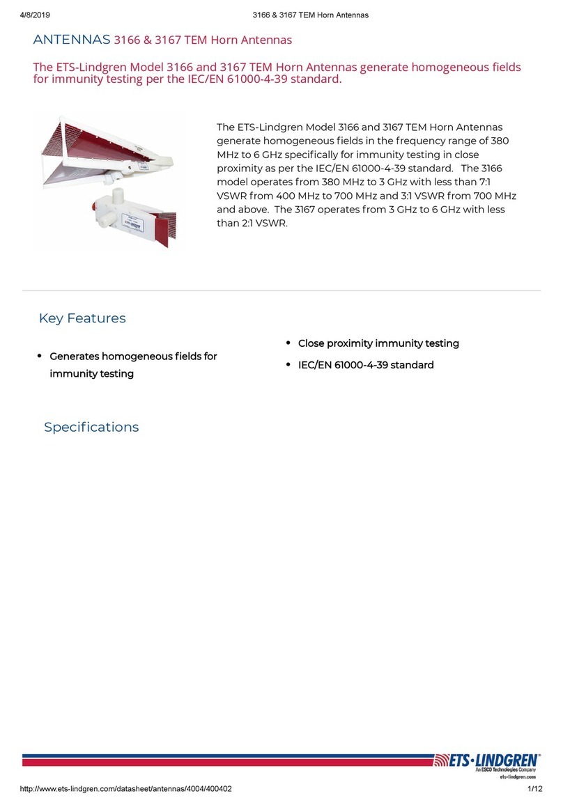
ESCO Technologies ETS Lindgren 3166 User manual
ESCO Technologies
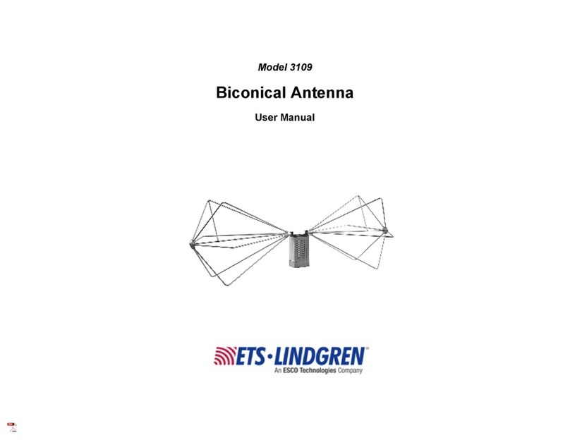
ESCO Technologies ETS-Lindgren 3109 User manual
ESCO Technologies
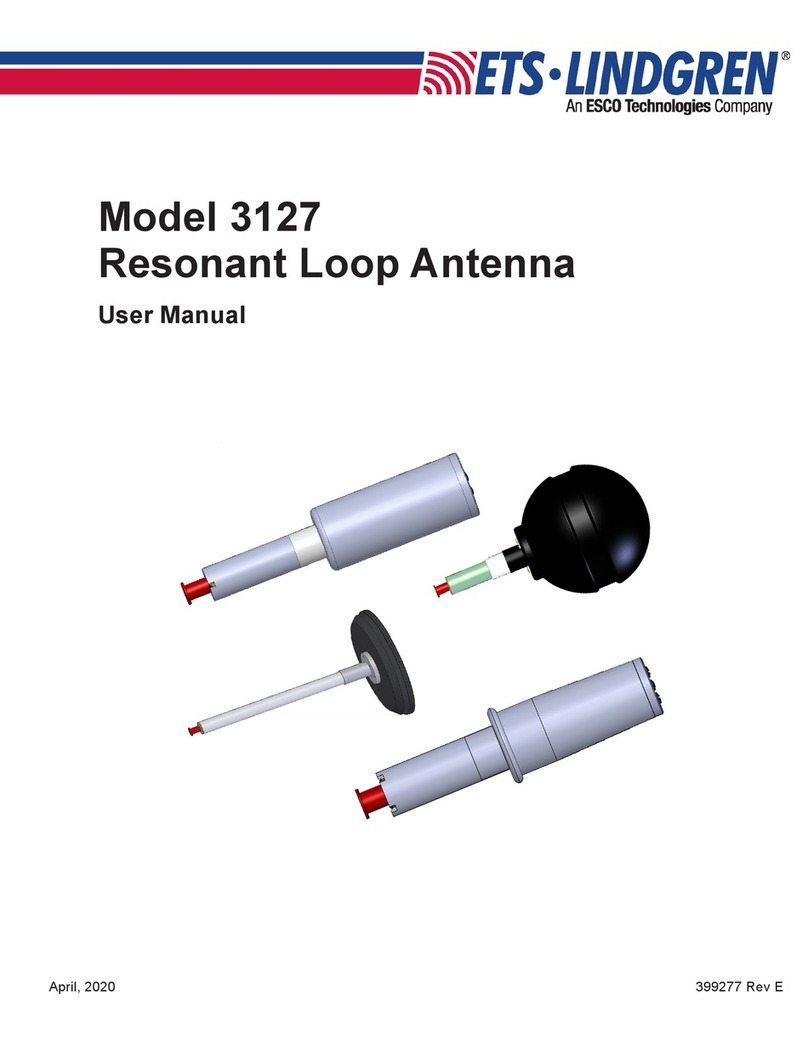
ESCO Technologies ETS LINDGREN 3127 User manual

ESCO Technologies
ESCO Technologies ETS LINDGREN 3158 User manual
ESCO Technologies
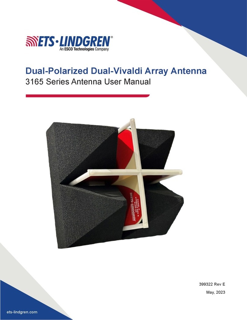
ESCO Technologies ETS-LINDGREN 3165 Series User manual
ESCO Technologies
ESCO Technologies ETS-LINDGREN BiConiLog 3142E User manual

ESCO Technologies
ESCO Technologies ETS-Lindgren 3147 User manual
ESCO Technologies
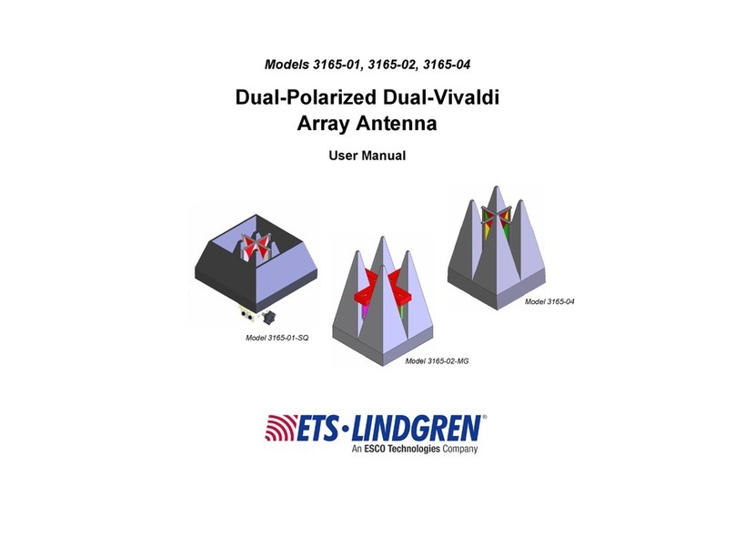
ESCO Technologies ETS-Lindgren 3165-01 User manual

ESCO Technologies
ESCO Technologies ETS Lindgren 3112 User manual
ESCO Technologies
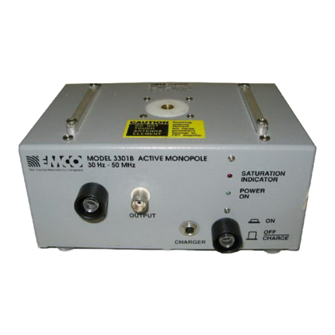
ESCO Technologies ETS-Lindgren 3301B User manual
ESCO Technologies
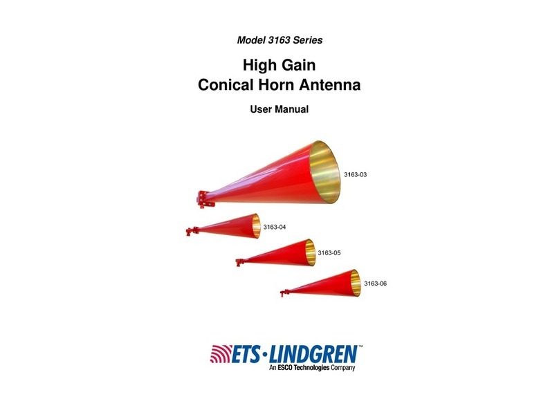
ESCO Technologies ETS-Lindgren 3163-03 User manual
Popular Antenna manuals by other brands

Alfa Network
Alfa Network APA-L01 Specifications

Naval
Naval PR-422CA Operation manual

Feig Electronic
Feig Electronic ID ISC.ANTH200/200 Series manual

TERK Technologies
TERK Technologies TV44 owner's manual

Directive Systems & Engineering
Directive Systems & Engineering DSE2324LYRMK quick start guide

HP
HP J8999A instructions

CommScope
CommScope CMAX-OMFX-43M-I53 Installation instruction

Ramsey Electronics
Ramsey Electronics DAP25 Kit assembly and instruction manual

COBHAM
COBHAM SAILOR 800 VSAT Replacement procedure

Trango Systems
Trango Systems AD900-9 Specification sheet

Steren
Steren ANT-100 user manual

IWCS
IWCS iriBelt II Quick start user guide


