Hemisphere GPS S321 Non-UHF User manual

875-0357-D
User Guide
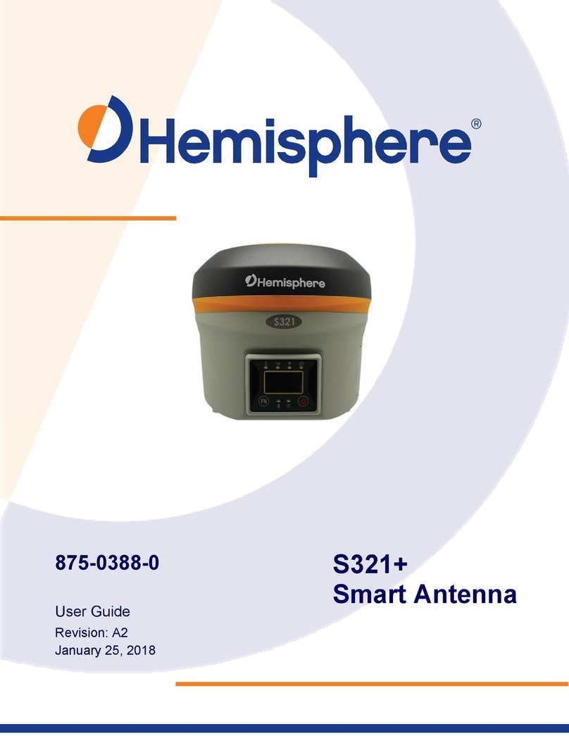
S321 Smart
Antenna
Revision: A8
February 16, 2018

i
This device complies with part 15 of the FCC Rules. Operation is subject to the following two conditions:
(1)
This device may not cause harmful interference, and
(2)
this device must accept any interference received, including interference that may
cause undesired operation.
ThisproductcomplieswiththeessentialrequirementsandotherrelevantprovisionsofDirective2014/53/EU.Thedeclarationofconformitymaybe
consultedathttps://hemispheregnss.com/About‐Us/Quality‐Commitment.
Copyright Notice
Copyright Hemisphere GNSS, Inc. (2018). All rights reserved.
No part of this manual may be reproduced, transmitted, transcribed, stored in a retrieval system or
translated into any language or computer language, in any form or by any means, electronic,
mechanical, magnetic, optical, chemical, manual or otherwise, without the prior written permission of
Hemisphere GNSS.
Trademarks
Hemisphere GNSS®, the Hemisphere GNSS logo, TRACERTM, Crescent®, EclipseTM, e-Dif®, L-DifTM,
miniEclipseTM, PocketMax3 PCTM, PocketMax3TM, PocketMax3TM, S320TM, SBX-4TM, VectorTM,
XF1TM,and XF2TM are proprietary trademarks of Hemisphere GNSS, Inc. Other trademarks are the
properties of their respective owners.
Patents
Hemisphere GNSS products may be covered by one or more of the following patents:
U.S. Patents
Australia Patents
6111549 6876920 7400956 8000381 8214111 2002244539
6397147 7142956 7429952 8018376 8217833 2002325645
6469663 7162348 7437230 8085196 8265826 2004320401
6501346 7277792 7460942 8102325 8271194
6539303 7292185 7689354 8138970 8307535
6549091 7292186 7808428 8140223 8311696
6711501 7373231 7835832 8174437 8334804
6744404 7388539 7885745 8184050 RE41358
6865465 7400294 7948769 8190337
Other U.S. and foreign patents pending.
Notice to Customers
Contact your local dealer for technical assistance. To find the authorized dealer
near you:
Hemisphere GNSS, Inc
8515 East Anderson Drive
Scottsdale, AZ 85255 USA
Phone: (480) 348-6380
Fax: (480) 270-5070
precision@hgnss.com
www.hgnss.com
Technical Support
If you need to contact Hemisphere GNSS Technical Support:
Hemisphere GNSS, Inc.
8515 East Anderson Drive
Scottsdale, AZ 85255 USA
Phone: (480) 348-6380
Fax: (480) 270-5070
Documentation Feedback
Hemisphere GNSS is committed to the quality and continuous improvement of our products and
services. We urge you to provide Hemisphere GNSS with any feedback regarding this guide by writing
to the following email
address: techsupport@hgnss.com.

ii
Table of Contents
Copyright Notice ............................................................................................................................................. i
Trademarks .................................................................................................................................................... i
Patents ........................................................................................................................................................... i
Notice to Customers ....................................................................................................................................... i
Technical Support .......................................................................................................................................... i
Documentation Feedback .............................................................................................................................. i
Table of Contents .......................................................................................................................................... ii
Terms and Definitions .................................................................................................................................. v
Chapter 1: Introduction .................................................................................................................................. 1
Introduction ................................................................................................................................................... 2
Product Overview ........................................................................................................................................ 2
Athena RTK ............................................................................................................................ 2
Atlas L-band ............................................................................................................................ 3
aRTK Position Aiding .............................................................................................................. 3
SureFix RTK Position ............................................................................................................. 4
What’s Included in your Kit .......................................................................................................................... 4
Chapter 2: Installation ................................................................................................................................... 6
Chapter 2: Installation ................................................................................................................................... 7
Ports and Connections ................................................................................................................................ 7
Installing/Connecting S321 .......................................................................................................................... 8
Installing Batteries .................................................................................................................. 8
Installing UHF and GSM Antennas ............................................................................................................. 9
Installing S321 on a Tribrach ..................................................................................................................... 10
Installing the S321 on a Range Pole ......................................................................................................... 10
Connecting to a Power Source .................................................................................................................. 11
Connecting to an External Device ............................................................................................................. 12
Using the Device “FN” and “I” Keys ...................................................................................... 12
Powering the S321 On/Off ......................................................................................................................... 13
Inserting and Removing the MicroSD Card/SIM Card .............................................................................. 13
Resetting the S321 .................................................................................................................................... 14
Chapter 3: Setup and Configuration ........................................................................................................... 15
Chapter 3: Setup and Configuration ........................................................................................................... 16
Control Panel Overview ............................................................................................................................. 16
Satellite LED (Green) ............................................................................................................ 16

iii
Bluetooth LED (Blue) ............................................................................................................ 17
Wi-Fi-LED (Green) ................................................................................................................ 18
External Data Link or Internal UHF Radio LED (Green) ....................................................... 18
Network LED (Green) ........................................................................................................... 19
S321 Menu Structure and Information .................................................................................. 20
Operating Mode Settings ...................................................................................................... 2 0
General Settings ................................................................................................................... 21
Setting up the S321 ................................................................................................................................... 22
Installing the Base ................................................................................................................ 22
Installing the Rover ............................................................................................................... 22
Bluetooth Communication ......................................................................................................................... 23
Hemisphere WebUI ................................................................................................................................... 23
Initial Setup ........................................................................................................................... 23
WebUI Start-up ..................................................................................................................... 24
Install New Firmware ............................................................................................................ 26
GNSS Registration ............................................................................................................... 26
Security ................................................................................................................................. 26
View Log ............................................................................................................................... 26
Formatting/Self Test/Reset ................................................................................................... 2 6
WebUI Settings .......................................................................................................................................... 27
Working Mode: UHF ............................................................................................................. 27
System Modes ...................................................................................................................... 29
Data Links ............................................................................................................................. 30
Internal UHF ......................................................................................................................... 31
External ................................................................................................................................. 32
Network ................................................................................................................................. 33
NTRIP ................................................................................................................................... 33
TCP/IP .................................................................................................................................. 34
Rover/Bluetooth .................................................................................................................... 36
Static ..................................................................................................................................... 36
Device Configuration ............................................................................................................ 37
NMEA Message .................................................................................................................... 38
Satellites ............................................................................................................................... 38
Firmware Update .................................................................................................................. 39
Updating Firmware via WebUI .............................................................................................. 39
Updating Firmware via MicroSD Card .................................................................................. 41
How to Download Static Data ............................................................................................... 41
How to Calibrate S321 Internal Sensors .............................................................................. 42
iv
Appendix A: Radio Mode ............................................................................................................................ A1
Appendix B: Troubleshooting ...................................................................................................................... B1
Appendix C: Technical Specifications ........................................................................................................ C3

v
Terms and Definitions
The following table lists the terms and definitions used in this document.
Term Definition
1PPS 1 pulse-per-second is a pulse that is output by the receiver
precisely once a second and is used for hardware
s
y
nchronization.
Activation Activation refers to a feature added through a one-time
purchase. For features that require recurring fees, see
Subscription.
aRTK aRTK is a Hemisphere GNSS exclusive service that uses
Atlas to extrapolate the last RTK correction during an RTK
outage so that the length of time an RTK position can be used
after an RTK outa
g
e is extended.
Atlas Atlas is a subscription-based service provided by Hemisphere
to achieve sub-decimeter accuracy after a twenty-minute
convergence period without the need for a base station or
datalink.
Base Station The Base Station is a receiver placed over a familiar point.
The base station then provides real-time observations and
sends these to nearby RTK rovers via UHF radio or the
internet.
BeiDou BeiDou is a Chinese satellite-based navigation system.
Datalink Datalink is the device used to send RTK or DGNSS
corrections from a base station to one of more rovers.
Common datalinks are UHF radio or Ntrip
(
see Ntrip
)
.
DGPS/DGNSS Differential GPS/GNSS refers to a receiver using Differential
Corrections.
Differential Corrections A method of improving precision of a GNSS rover. Two GNSS
receivers placed in a nearby area will have similar error. A
base station is placed over a known point. Since the actual
position of the base station is known, error can be calculated,
and corrections can then be applied to nearby rovers. This
differs from RTK
(
see section on RTK
)
.
Dual-Frequency Dual-Frequency use both L1 and L2 signals from GPS
satellites, G1 and G2 signals from GLONASS satellites, and
B1 and B2 signals from BeiDou satellites. Single frequency
receivers will onl
y
use L1, G1, and B1.
EGNOS European Geostationary Navigation Overlay Service
(EGNOS) is a satellite-based augmentation system (SBAS)
that provides free differential corrections over satellite in parts
of Europe.

vi
Terms and Definitions (continued)
Term Definition
Elevation Mask Elevation Mask is the minimum angle between a satellite and
the horizon for the receiver to use that satellite in the solution.
Satellites near the horizon often provide noisy signals and
should be avoided.
Firmware Firmware is the software loaded into the receiver that controls
the functionalit
y
of the receiver and runs the GNSS en
g
ine.
GALILEO Galileo is a global navigation satellite system implemented by
the European Union and European Space Agency. Global
coverage is available, and the full constellation is expected by
2020.
GAGAN GPS Aided Geo Augmented Navigation is a satellite-based
augmentation system (SBAS) that provides free differential
corrections over satellite in India.
GLONASS Global Orbiting Navigation Satellite System (GLONASS) is a
Global Navigation Satellite System (GLONASS) deployed,
and maintained, by Russia. It is comparable to the United
States’ GPS s
y
stem.
GNSS Global Navigation Satellite System (GNSS) is a system that
provides autonomous 3D position (latitude, longitude, and
altitude) along with very accurate timing globally by using
satellites. Current GNSS providers are: GPS, GLONASS and
Galileo. BeiDou is expected to have
g
lobal covera
g
e b
y
2020.
GPS Global Positioning System (GPS) is a global navigation
satellite s
y
stem implemented b
y
the United States.
Heading Heading is the angle between true north and the vector
calculated from the primar
y
to secondar
y
antenna.
Heading Bias Heading Bias is an offset applied to the heading value the
receiver calculates.
Mountpoint Mountpoints are the specified data streams in Ntrip. Multiple
base stations may send data to an Ntrip caster. Each base
station has a unique Mountpoint.
Multipath Multipath occurs when the GNSS signal reaches the antenna
by two or more paths. This causes incorrect pseudo-range
measurements and leads to less precise GNSS solutions.
NMEA National Marine Electronics Association (NMEA) is a marine
electronics organization that sets standards for
communication between marine electronics.

vii
Terms and Definitions (continued)
Term Definition
Ntrip Networked Transport of RTCM via Internet Protocol (Ntrip) is
a protocol for streaming GNSS data over the internet. Ntrip is
most often used to stream RTK or DGNSS corrections over
the internet.
Ntrip Caster Ntrip casters receive data from one or more Ntrip servers and
the data is available to one or more Ntrip clients. Each data
source (Ntrip server) must send the data to a specified Ntrip
mountpoint, and the Ntrip client must specify which
mountpoint to receive data from. This allows multiple base
stations on the same network.
Ntrip Client Ntrip clients receive data from the Ntrip caster and provide
this data
(
often over GSM or serial
)
to the GNSS receiver.
Ntrip Server The Ntrip server sends data from the Ntrip source (base
station
)
to the Ntrip caster.
QZSS Quasi-Zenith Satellite System (QZSS) is a satellite navigation
s
y
stem currentl
y
under development in Japan.
ROX ROX is a Hemisphere GNSS propriety RTK message format
that can be used as an alternative to RTCM3 when both the
base and rover are Hemisphere branded.
RTCM Radio Technical Commission for Maritime Services (RTCM) is
a standard used to define RTK message formats so that
receivers from an
y
manufacturer can be used to
g
ether.
RTK Real-Time-Kinematic (RTK) is a real-time differential GPS
method that provides better accuracy than differential
corrections.
SBAS Satellite Based Augmentation System (SBAS) is a system that
provides differential corrections over satellite throughout a
wide area or re
g
ion.
Signal-to-Noise Ratio Signal-to-Noise Ratio (SNR) is the ratio of the message
content of the si
g
nal a
g
ainst the noise of the si
g
nal.
Subscription A subscription is a feature that is enabled for a limited time.
Once the end-date of the subscription has been reached, the
feature will turn off until the subscription is renewed.
WAAS Wide Area Augmentation System (WAAS) is a satellite-based
augmentation system (SBAS) that provides free differential
corrections over satellite in parts of North America.

S321 User Guide Chapter 1 - Introduction Page 1 of 65
Chapter 1: Introduction
Product Overview
Key Features
What’s Included in your Kit
Firmware Upgrades

S321 User Guide Chapter 1 - Introduction Page 2 of 65
Introduction
This User Guide provides information to help you quickly set up your S321 Smart Antenna.
Product Overview
The S321 is an all‐new multi‐GNSS, multi‐frequency smart antenna designed by and for
surveyors. The S321 delivers robust performance and high precision in the field with a compact
and rugged package.
With multiple wireless communications ports and an open GNSS interface, the S321 can be used
in a variety of operating modes in a network or crew. Use the S321 as a precise base station
sending RTK or Atlas L‐band corrections to your existing rover network.
Turn S321 into a lightweight and easy to use rover by connecting it to your base via UHF radio or
Wi‐Fi network. The built‐in WebUI is used to control, manage, and upgrade the S321 with new
firmware and activations. S321 is Athena enabled and Atlas capable.
Athena RTK
Athena RTK (Real Time Kinematic) technology is available on Eclipse‐based GNSS receivers.
Athena RTK requires the use of two separate receivers: a stationary base station (primary
receiver) that broadcasts corrections over a wireless link to the rover (secondary receiver). The
localized corrections are processed on the rover to achieve superior accuracy and repeatability.
Performance testing has shown positioning accuracy at the centimeter level.
Athena RTK has the following benefits:
Improved Initialization time ‐Performing initializations in less than15 seconds at better
than 99.9% of the time
Robustness in difficult operating environments ‐Extremely high productivity under the
most aggressive of geographic and landscape-oriented environments
Performance on long baselines ‐Industry‐leading position stability for long baseline
applications
Note: Throughout the rest of this User Guide the S321 Smart Antenna is referred to
simply as the S321.

S321 User Guide Chapter 1 - Introduction Page 3 of 65
Atlas L-band
Atlas L‐band corrections are available worldwide. With Atlas, the positioning accuracy does not
degrade as a function of distance to a base station, as the data content is not composed of a
single base station’s information, but an entire network’s information.
Atlas L‐band is Hemisphere's industry leading correction service, which can be added as a
subscription. Atlas L‐ band has the following benefits:
Positioning accuracy ‐ Competitive positioning accuracies down to 2 cm rms in
certain applications
Positioning sustainability ‐ Cutting edge position quality maintenance in the absence
of correction signals, using Hemisphere’s patented technology
Scalable service levels ‐ Capable of providing virtually any accuracy, precision and
repeatability level in the 2 to 100 cm range
Convergence time ‐ Industry‐leading convergence times of 10‐40 minutes
S321 is supported by our easy‐to‐use Atlas Portal (www.atlasgnss.com), which empowers you to
update firmware and enable functionality, including Atlas subscriptions for accuracies from meter
to sub‐decimeter levels.
For more information about Athena RTK, see:https://hemispheregnss.com/Technology For more
information about Atlas L‐band, see: https://hemispheregnss.com/atlas
aRTK Position Aiding
aRTK is an innovative feature available in Hemisphere’s S321 smart antenna that greatly
mitigates the impact of land‐based communication instability. Powered by Hemisphere’s Atlas L‐
band system service, aRTK provides an additional layer of communication redundancy to RTK
users, assuring that productivity is not impacted by intermittent data connectivity.
S321 receives the aRTK augmentation correction data over satellite, while also receiving the
land‐ based RTK correction data. With this, the receiver internally operates with two sources of
RTK correction, creating one additional layer of correction redundancy as compared to typical
RTK systems.
Once that process is established (less than a few seconds), the receiver can operate in the
absence of either correction source, or in other words, the receiver is able to continue generating
RTK positions in case the land‐based RTK correction source becomes unavailable for a period of
time.
Note: To use aRTK, you are required to change the RTK timeout to: 2700 s. This can be
accomplished by following the WebUI directions outlined in the Setup and Configuration section
of this document.
If your S321 is equipped with a 400 MHz radio you may be required to obtain a
valid radio license for your jurisdiction.

S321 User Guide Chapter 1 - Introduction Page 4 of 65
SureFix RTK Position
To provide high fidelity quality indicators to the users, Hemisphere created an additional
processor that runs in combination with the RTK engine, called the SureFix processor.
The SureFix processor takes several inputs, such as GNSS data, data preprocessing results, and
generated RTK solutions. The SureFix processor takes all available information and, by using
functional and stochastic analysis methods, determines the quality of the current RTK engine
solution. These are shown as “SureFix quality indicators”. The SureFix indicators are then
combined with the RTK solution before being provided to the user. At the end of the process, the
user has access to high fidelity information about the quality of the RTK solution.
What’s Included in your Kit
As per Table 1.1 below, the S321 is available in a variety of kits, with supplementary products
sold as “controller/option kits”, “accessory kits” or simply as separate accessories. Contents can
change without prior notice. Check the official price list to confirm contents.
Important: Charge your Li-on battery upon receipt of shipment. According to the 2017 IATA
Dangerous Goods Regulations and supplemental IATA Lithium Battery Guidance, batteries must
be charged to less than 30% to meet international air freight requirements.

S321 User Guide Chapter 1 - Introduction Page 5 of 65
Table 1-1: S321 parts list
Main Kits Part Number 940-2145-0
S321U
940-2146-0
S321N
940-2163-0
S321U Int’l
940-2164-0
S321N Int’l
S321 UHF Smart Antenna 752‐0006‐0 1 - 1 -
S321 Network Smart Antenna 752‐0007‐0 - 1 - 1
S321 Serial Cable 051‐0390‐0 1 1 1 1
GSM/WCDMA External Antenna 150‐1023‐0 1 1 1 1
UHF External Antenna 150‐1024‐0 1 - 1 -
Athena dFreq RTK Bundle* 163-1045-0 1 1 - -
Smart Battery 427‐0058‐0 2 2 2 2
Battery Charger Adapter 427‐0060‐0 1 1 1 1
Battery Charger 427‐0063‐0 1 1 1 1
S321 Cigarette Lighter Adapter 427-0064-0 1 1 1 1
Tape Measure 699‐0006‐000 1 1 1 1
Quick Release 699-0015-0 1 1 1 1
Carry Case 750‐0183‐1 1 1 1 1
8 GB MicroSD Card 750‐1169‐0 1 1 1 1
Accessory Kits Part Number 940-2155-0
Base Acc
940-2156-0
Rover Acc
Accessor
y Only
S321 Power Cable (Alligator Clips) 054‐0171‐0 1 - -
S321 5-Pin Power
Cable (PacCrest/Rcvr)
054‐0172‐0 - - 1
S321 5-Pin Power Cable
(Satel/Rcvr)
054-0173-0 - - 1
S321 5-Pin Power Cable (Receiver) 054-0178-0 1 - -
S321 5-Pin Power cable
(Serial/Rcvr)
054-0180-0 - - 1
S321 UHF Antenna (TNC) 150-1026-0 1 - -
Mini Rotary Table 699-0014-0 - 1 -
S321 External UHF Antenna
Bracket Kit
710-0136-6 1 - -
Controller/Option Kits Part Number 940-2149-0
Cntrlr (NA)
940-2150-0
Cntrlr (EU)
940-2165-0
Int’l Option
XF3 Pole Bracket Mount 750-0159-0 1 1 1
XF3 (EU) 750-0177-0 - 1 1
XF3 (NA) 750-0178-0 1 - -
Carlson SurvCE v5.04+ (w/ NA) 750-2022-0 1 - -
Carlson SurvCE 5.04+ (w/o NA) 750-2023-0 - 1 1
Athena dFreq RTK Bundle* 163-1045-0 - - 1

S321 User Guide Chapter 2
–
Installation Page 6 of 65
Chapter 2: Installation
Ports and Connections
Installing/Connecting S321
Installing UHF and GSM Antennas
Installing S321 on a Tribrach
Installing S321 on a Range Pole
Connecting to a Power Source
Connecting to an External Device
Powering the S321 On/Off
Inserting and Removing the MicroSD/SIM Card
Resetting the S321

S321 User Guide Chapter 2-Installation Page 7 of 65
Chapter 2: Installation
Ports and Connections
All ports and connections are located on the bottom of the unit, as shown in Figure 2‐1. Table 2‐1
provides additional information about each port/connection.
Figure 2-1: S321 ports and connectors
Table 2-1: S321 ports and connections
Port What to connect
7‐pin Diagnostic Port (LEMO) Diagnostic cable for serial or USB
5‐pin Power/Data Port (LEMO) External power, data and radio devices
GSM Antenna Connector External GSM antenna
UHF Antenna Connector External UHF antenna
Mounting hole Pole or tripod mount

S321 User Guide Chapter 2-Installation Page 8 of 65
Installing/Connecting S321
Installing Batteries
The S321 allows for one battery (11.1 V ‐ 37.74 Wh) to be installed at a time. When installing the
battery, ensure the contact points are facing up towards the “Hemisphere” logo. Slide the battery
into the designated spot until the “battery tension bar” clicks into place. The projected run time of
the battery is 6 hours in the UHF receive mode.
The S321 kit provides two batteries, as noted in the What’s Included in your Kit portion of this
User Guide.
Figure 2-2: Battery installation

S321 User Guide Chapter 2-Installation Page 9 of 65
Installing UHF and GSM Antennas
To install the UHF portion of the S321 antenna, locate the UHF antenna (150‐1024‐0) from the kit
list under What’s Included in your Kit. Insert the connector end of the UHF antenna and rotate
clockwise to secure the antenna to the S321. To install the GSM portion of the S321 antenna,
locate the GSM antenna (150‐1023‐0) from the kit list under. Insert the connector end of the
GPRS antenna and rotate clockwise to secure the antenna to the S321.
Figure 2-3: Installing UHF and GSM antennas
Note: Only one antenna (UHF or GSM) can be connected to the S321 at a time.

S321 User Guide Chapter 2-Installation Page 10 of 65
Installing S321 on a Tribrach
The S321 mounts flush to the tribrach, by securing the 5/8-11” female metal mounting portion of
the S321 to the standard 5/8-11” male portion of the tribrach. Hand-tighten (35‐40 in-lbs. of
torque) to secure the S321 onto the mount in a clockwise rotation.
Figure 2-4: Installing S321 on a tribrach
Installing the S321 on a Range Pole
Using the standard 5/8-11” mount on the bottom of the S321, you can secure the unit to a field
standard 5/8-11” range pole. the S321 should be placed carefully on the range pole, to ensure
cross‐threading does not occur, while rotating the unit in a clockwise direction.
Hand-tighten (35‐40 in-lbs. of torque) to secure the unit.
Figure 2-6: Range pole installation

S321 User Guide Chapter 2-Installation Page 11 of 65
Connecting to a Power Source
The S321 has two main power sources. The first being an internal, removable battery which is
described in the earlier portion of this chapter. The second source of power is the external power
cable (054‐0171‐0). The 5‐pin (LEMO) connector allows 9 to 24V of power into the S321.
Figure 2-7: External power connector

S321 User Guide Chapter 2-Installation Page 12 of 65
Connecting to an External Device
The 7‐pin connector is available for troubleshooting, debugging, and USB log downloads.
Figure 2-8: External device connector
Using the Device “FN” and “I” Keys
The on‐device menu can be navigated by using the on‐device keys. The FN key allows you to
scroll through each item on the device menu display. The I key acts as an enter key for selecting
to required menu option. The I key also acts as a power key when the menu option of “power” is
selected. (See Powering the S321 On/Off below).
Figure 2-9: S321 on-device menu
Table of contents
Other Hemisphere GPS Antenna manuals

Hemisphere GPS
Hemisphere GPS S321+ User manual

Hemisphere GPS
Hemisphere GPS Crescent V100 Series User manual

Hemisphere GPS
Hemisphere GPS Crescent V100 Series User manual

Hemisphere GPS
Hemisphere GPS C321 User manual

Hemisphere GPS
Hemisphere GPS A325 User manual

Hemisphere GPS
Hemisphere GPS A222 User manual

Hemisphere GPS
Hemisphere GPS Crescent A100 User manual

Hemisphere GPS
Hemisphere GPS A221 User manual

Hemisphere GPS
Hemisphere GPS A326 AtlasLink User manual

Hemisphere GPS
Hemisphere GPS Crescent A100 User manual