Esco LP-12 User manual

INSTALLATION, OPERATION
AND MAINTENANCE MANUAL
WITH PARTS LIST
LP SERIES PUMP
Thomas Pump & Machinery
120 Industrial Drive
Slidell, LA 70460
PH: 985-649-3000
Fax: 985-649-4300
MODEL
LP -12

1
TABLE OF CONTENTS
INTRODUCTION........................................................................................... Pg. 03
WARNING – SECTION A ............................................................................ Pg. 04
INSTALLATION – SECTION B.................................................................... Pg. 05
Pump Dimensions...................................................................... Pg. 05
PREINSTALLATION INSPECTION................................................. Pg. 06
POSITIONING PUMP...................................................................... Pg. 06
Lifting.......................................................................................... Pg. 06
Mounting..................................................................................... Pg. 06
Clearance................................................................................... Pg. 06
SUCTION AND DISCHARGE PIPING............................................. Pg. 06
Materials..................................................................................... Pg. 06
Line Configuration...................................................................... Pg. 07
Connections to Pump................................................................. Pg. 07
Gauges....................................................................................... Pg. 07
SUCTION LINES.............................................................................. Pg. 07
Fittings........................................................................................ Pg. 07
Strainers..................................................................................... Pg. 07
Sealing....................................................................................... Pg. 07
Suction Lines in Sumps.............................................................. Pg. 07
Suction Lines Positioning........................................................... Pg. 08
DISCHARGE LINES......................................................................... Pg. 08
Siphoning................................................................................... Pg. 08
Valves......................................................................................... Pg. 08
Bypass Lines.............................................................................. Pg. 09
AUTOMATIC AIR RELEASE VALVE............................................... Pg. 10
Theory of Operation................................................................... Pg. 10
Air Release Valve Installation..................................................... Pg. 10
ALIGNMENT.................................................................................... Pg. 11
Coupled Drivers.......................................................................... Pg. 12
V-Belt Drives.............................................................................. Pg. 12
OPERATION – SECTION C......................................................................... Pg. 14
PRIMING.......................................................................................... Pg. 14
STARTING....................................................................................... Pg. 14
Rotation...................................................................................... Pg. 14
OPERATION.................................................................................... Pg. 15
Lines With a Bypass................................................................... Pg. 15
Lines Without a Bypass.............................................................. Pg. 15
Leakage...................................................................................... Pg. 15
Liquids Temperature and Overheating....................................... Pg. 15
Strainer Check............................................................................ Pg. 16
Pump Vacuum Check................................................................. Pg. 16
STOPPING....................................................................................... Pg. 16
Cold Weather Preservation........................................................ Pg. 16
BEARING TEMPERATURE CHECK............................................... Pg. 16

2
TABLE OF CONTENTS
(Continued)
TROUBLESHOOTING – SECTION D ………………………............ Pg. 18
PUMP MAINTENANCE AND REPAIR – SECTION E……….......... Pg. 21
PERFORMANCE CURVE……………………………………….......... Pg. 21
Pump Model and Repair Rotating Assembly ....………….......... Pg. 22
PARTS LISTS ................................................................................. Pg. 23
PUMP AND SEAL DISASSEMBLY AND REASSEMBLY…............ Pg. 25
Suction Check Valve Disassembly ………………………........... Pg. 25
Pump Disassembly …………………………………………......... Pg. 25
Seal Disassembly …………………………..………………......... Pg. 26
Impeller Shaft and Bearing Disassembly .......……………......... Pg. 27
Impeller Shaft and Bearing Reassembly ……….........….......... Pg. 27
Seal Reassembly …………..……….……………………............ Pg. 28
Pump Reassembly …………………………………………......... Pg. 29
Suction Check Valve Reassembly ………………………............ Pg. 30
LUBRIFICATION ............................................................................ Pg. 30
Seal Assembly ......................................................................... Pg. 30
Bearings .................................................................................... Pg. 30

3
INTRODUCTION
If there are any questions regarding the pump or its applications which are not covered in this manual or in other
literature accompanying this unit, please contact your Bombas Esco S/A distributor, or write:
Thomas Pump & Machinery
120 Industrial Drive
Slidell, LA 70460
Ph: 985-649-3000
Fax: 985-649-4300
For information or technical assistance on the power source, contact the power source manufacture’s local
dealer or representative.
The following are used to alert maintenance personnel to procedures which require special attention, to those
which could damage equipment, and to those which could be dangerous to personnel:
This Installation, Operation, and
Maintenance manual is designed to help
you get the best performance and
longest lifefromyourEscopump.
Thispump isanLP Series,semi-open
impeller, self-
priming centrifugal model with a suction
check valve. The pump is designed fo
r
handling mild industrial corrosives, mud o
r
slurries containing large entrained solids. The
basic material of construction is gray iron,
with ductile iron impeller and steel wearing
parts.
DANGER!
Immediate hazards w hich WILL result in
severe personal injury or death. These
instructions describe the procedure required
and the injury w hich w ill result from failure
to follow procedure.
CAUTION!
Hazards or unsafe practices which COULD
result in minor personal injury or product or
property damage. These instructions describe
the requirements and the possible damage
w hich could result from failure to follow the
p
rocedure. NOTE
Instructions to aid in installation, operation,
and maintenance or which clarify a procedure.

4
SAFETY – SECTION A
These warnings applytoLP series basicpumps.
Bombas Esco has no control over or particula
r
knowledge of the power source which will be
used. Refer to the manual accompanying the
power source before attempting to begin
operation.
WARNING!
After the pump has been positioned, make
certain that the pump and all piping
connections are tight, properly supported and
secure before operation.
WARNING!
Do not operate the pump without the guards in
place over the rotating parts.
Exposed rotating parts can catch clothing,
fingers, or tools, causing severe injury to
personnel.
WARNING!
Do not operate the pump against a closed
discharge valve for long periods of time. If
operated against a closed discharge valve, pump
components w ill deteriorate, and the liquid could
come to a boil, pressure, and cause the pump
casing to rupture or explode .
WARNING!
Before attempting to open or service the
pump:
1. Familiarize yourself w ith this manual.
2. Disconnect or lock out the power source to
ensure that the pump w ill remain inoperative.
3. Allow the pump to cool if overheated.
4. Check the temperature before opening any
covers, plates, or plugs.
5. Close the suction and discharge valves.
6. Vent the pump slowly and cautiously.
7. Drain the pump
WARNING!
This pump is designed to handle mild
industrial corrosives, mud or slurries
containing large entrained solids. Do no
t
attempt to pump volatile, corrosive, o
r
flammable materials w ihch may damage the
pump or endanger personnel as result o
f
pump failure.
WARNING!
Do not remove plates, covers, gauges, pipe
plugs, or fittings from an overheated pump.
Vapor pressure within the pump can cause parts
being disengaged to be ejected with great force.
Allow the pump to cool before servicing.
WARNING!
Use lifting and moving equipment in good repair
and with adequate capacity to prevent injuries to
personnel or damage to equipment. Suction and
discharge hoses and piping must be removed
form the before lifting

5
INSTALLATION – SECTION B
OUTLINE DRAWING
Figure1. Pump Model LP -12
Review all SAFETY information in Section A.
Since pump installations are seldom identical, this
section offers only general recommendations and
practices required to inspect, position and arrange
the pump and piping.
Most of the information pertains to a standard
static lift application where the pump is
positioned above the level of liquid to be pumped.
If installed in a flooded suction application
where the liquid is supplied to the pump unde
r
pressure, some of the information such as
mounting, line configuration, and priming must be
tailored to the specific application.
Since the pressure supplied to the pump is critical to
performance and safety, be sure to limit incoming
pressure to 50% of the maximum p ermissible
operating pressure as shown on the pump
performance curve.
For further assistance, contact your Bombas Esco
distributor or the Bombas Esco Company.
Pump Dimensions
See Figure 1 for the approximate physical
dimensions of this pump.
466.90
[18.38]
345.90
[13.62]
1474.70
[58.06]
69.90
[2.75]
160.80
[6.31]
1621.50
[63.84] 650.00
[25.59]
1474.70
[58.06]
971.50
[38.25]
121.40
[4.78]
121.40
[4.78]
508.00
[32.00]
272.00
[10.71]
174.80
[6.88]
509.75
[20.00]
95.30
[3.75]
101.60
[4.00]
270.10
[10.63]
203.20
[8.00]
203.20
[8.00]
203.20
[8.00]
167.90
[6.59]
508.00
[20.00]
342.90
[13.58]
503.20
[19.01]
[.19]
9.6 x 4.8 x 127.0
[.38] [5.00]
DIMENSIONS: MILLIMETERS
(INCHES)

6
PREINSTALLATION INSPECTION POSITIONING PUMP
The pump assembly was inspected and tested
before from the factory. Before installation, inspect
the pump for damage which may have occurred
during shipment. Check as follows:
a. inspect the pump for cracks, dents,
damaged threads, and other obvious
damage.
b. Check for and tighten loose attaching
hardware. Since gaskets tend to shrin
k
after drying, check for loose hardware at
mating surfaces.
c. Carefully read all warnings and cautions
contained in this manual or affixed to the
pump, and perform all duties indicated.
Note the direction of rotation indicated on
the pump. Check that the pump shaft
rotates counterclockwise when facing the
back cover plate assembly/impeller end of
the pump.
Lifting
Use lifting equipment with a capacity of at least
13.230 pounds (6000 Kg). This pump weighs
approximately 2350 pounds (1066 Kg), not
including the weight of accessories and base.
Customer installed equipment such as suction and
discharge piping must be removed before
attempting to lift.
CAUTION!
The pump assembly can be seriously
damaged if the cables or chains used to lift
and move the unit are improperly wrapped
around the pump.
CAUTION!
Only operate this pump in the direction
indicate by the arrow on the pump body and
on the accompanying decal. Refer to
ROTATION in OPERATION, Section C.
d. Check levels and lubricate as
necessary. Refer to LUBRICATION in the
MAINTENANCE AND REPAIR section of
this manual and perform duties as
instructed.
e. If the pump and power source have
been stored for more than 12 months,
some of the components or lubricants may
have exceeded their maximum shelf life.
These must be inspected or replaced to
ensure maximum pump service.
If the maximum shelf life has been exceeded,
or if anything appears to be abnormal, contact
your Bombas Esco distributor or the factory to
determine the repair or updating policy. Do not
put the pump into service until appropriate
action has been taken.
Mounting
Locate the pump in an accessible place as close as
practical to the liquid being pumped. Level mounting
is essential for proper operation.
The pump may have to be supported or shimmed to
provide for level operation or to eliminate vibration.
Clearance
When positioning the pump, allow a minimum
clearance of 40 inches (800 mm) in front of the back
cover to permit removal of the cover and easy
access to the pump interior.
SUCTION AND DISCHARGE PIPING
Pump performance is adversely effected by
increase suction lift, discharge elevation. And friction
losses. See the performance curve and operating
range shown on Page 21 to be sure your overall
application allows pump to operate within the safe
operation range.
Materials
Either pipe or hose maybe used for suction and
discharge lines: however, the materials must be
compatible with liquid being pumped.

7
If hose is used In suction lines, it must be the
rigid-wall, reinforced type to prevent collapse
under suction. Using piping couplings in suction
lines is not recommended.
Line Configuration
Keep suction and discharge lines as straight as
possible to minimize friction losses. Make
minimum use of elbows and fittings, which
substantially increase friction loss. If elbows are
necessary, use the long radius type to minimize
friction loss.
Connections to Pump
Before tightening a connecting flange, align it
exactly with the pump port. Never pull a pipe line
into place by tightening the flange bolts and/o
r
couplings.
Lines near the pump must be independently
supported to avoid strain on the pump which
could cause excessive vibration, decrease
bearing life, and increased shaft and seal wear.
If hose-type lines are used, they should have
adequate support to secure them when filled
with liquid and under pressure.
Gauges
Most pumps are drilled and tapped for installing
discharge pressure and vacuum suction gauges.
If these gauges are desired for pumps that are
not tapped, drill and tap the suction and
discharge lines not less than 18 inches
(457,2mm) from the suction and discharge ports
and install the lines. Installation closer to the
pump may result in erratic readings.
SUCTION LINES
To avoid air pockets which could affect pump
priming, the suction line must be as short and
direct as possible. When operation involves a
suction lift, the line must always slope upward to
the pump from the source of the liquid being
pumped: if the line slopes down to the pump at
any point along the suction run, air pockets will
be created.
Fittings
Suction lines should be the same size as the pump
inlet. If reducers are used in suction lines, they should
be the eccentric type, and should be installed with the
flat part of the reducers uppermost to avoid creating
air pockets. Valves are not normally used in suction
lines, but if a valve is used, install it with the horizontal
to avoid air pockets.
Strainers
If a strainer is furnished with the pump, be certain to
use it; any spherical solids which pass through a
strainer furnished with the pump will also pass
through the pump itself.
If a strainer is not furnished with the pump, but is
installed by the pump user, make certain that the total
area of the openings in the strainer is at least three or
four times the cross section of the suction line, and
that the openings will not permit passage of solids
larger than the solids handling capability of the pump.
This pump is designed to handle up to 3 inch (76,2
mm) diameter spherical solids.
Sealing
Since even a slight leak will affect priming, head, and
capacity, especially when operating with a high
suction lift, all connections in the suction line should
be sealed with pipe dope to ensure an airtight seal.
Follow the sealant manufacturer’s recommendations
when selecting and applying the pipe dope. The pipe
dope should be compatible with the liquid being
pumped.
Suction Lines in Sumps
If a single suction line is installed in a sump, it should
be positioned away from the wall of the sump at a
distance equal to 1 ½ times the diameter of the
suction line.
If there is a liquid flow from an open pipe into the
sump, the flow should be kept away from the suction
inlet because the inflow will carry air down into the
sump, and air entering the suction line will reduce
pump efficiency.

8
VELOCITY (FT./SEC.)= QUANT. (G.P.M)x.321 OR G.P.M. x 4085
AREA D²
VELOCITY (M./SEC.)= FLOW (M./MIN)x21.22 OR FLOW (M³/SEC.)
DIAMETER IN MM² AREA IN M²
Figure 2. Recommended Minimum Suction Line Submergence vs. Velocity
If it is necessary to position inflow close to the suction
inlet, install a baffle between the inflow and the in
suction lines, it must be the rigid-wall, reinforced type
to prevent collapse under suction. Using piping
couplings in suction lines is not recommended.
Suction inlet at a distance 1 ½ times the diameter of
the suction pipe. The baffle will allow entrained air to
escape from the liquid before it is drawn into the
suction inlet.
If two suction lines are installed a single sump, the
flow paths may interact, reducing the efficiency of one
or both pumps. To avoid this, position the suction
inlets so that they are separated by a distance equal
to at least 3 times the diameter of the suction pipe.
Suction Line Positioning
The depth of submergence of the suction line is
critical to efficient pump operation. Figure 2 shows
Recommended minimum submergence vs. velocity.
NOTE
The pipe submergence required may be reduce
d
by installing a standard pipe increaser fitting at
the end of the suction line. The larger opening
size will reduce the inlet velocity. Calculate the
required submergence using the following
formula based on the increased opening size
(area or diameter).
DISCHARGE LINES
Siphoning
Do not terminate the discharge line at a level lowe
r
than of the liquid being pumped unless a siphon
breaker is used in the line. Otherwise, a siphoning
action causing damage to the pump could result.
Valves
If a throttling valve is desired in the discharge line,
use a valve as large as the largest pipe to minimize
friction losses. Never install a throttling valve in a
suction line.
With high discharge heads, it is recommended that a
throttling valve and a system check valve be installed
in the discharge line to protect the pump from
excessive shock pressure and reverse rotation when
it is stopped.

9
In high discharge head applications (more than
30 feet), an excessive amount of liquid may be
bypassed and forced back to the wet well under
the full working pressure of the pump; this will
reduce overall pumping efficiency. Therefore, it is
recommended that a Bombas Esco Automatic
Air Release Valve be installed in the bypass
line.
Bombas Esco Automatic Air Release Valves are
reliable, and require minimum maintenance. See
AUTOMATIC AIR RELEASE VALVE in this
section for installation and theory of operation of
the Automatic Air Release Valve. Contact the
Bombas Esco Company for selection of an
Automatic Air Release Valve to fit your application.
If the installation involves a flooded suction such as
below-ground lift station. A pipe union and manual
shut-off valve may be installed in the bleed line to
allow service of the valve without shutting down the
station, and to eliminate the possibility of flooding.
If a manual shut-off valve is installed anywhere in
the air release piping, it must be a full-opening ball
type valve to prevent plugging by solids.
DANGER!
If a manual shut-off valve is installed in a
bypass line, it must not be left closed during
operation. A closed manual shut-off valve may
cause a pump which has lost prime to continue
to operate without reaching prime, causing
dangerous overheating and possible explosive
rupture of the pump casing. Personnel could
be severely injured.
Allow an over-heated pump to cool before
servicing. Do not remove plates, covers,
gauges, or fittings from an overheated pump.
Liquid within the pump can reach boiling
temperatures, and vapor pressure within the
pump can cause parts being disengaged to be
ejected with great force. After the pump cools,
drain the liquid from the pump by removing the
casing drain plug. Use caution when removing
the plug to prevent injury to personnel from hot
liquid.
CAUTION!
If the application involves a high discharge head,
gradually close the discharge throttling valve before
stopping the pump.
Bypass Lines
Self-priming pumps are not air compressors. During
the priming cycle, air from the suction line must be
vented to atmosphere on the discharge side. If the
discharge line is open, this air a check valve has
been installed in the discharge line, the discharge
side of the pump must be opened to atmospheric
pressure through a bypass line installed between
the pump discharge an the check valve. A self-
priming centrifugal pump w ill not prime if there is
sufficient static liquid head to hold the discharge
check valve closed.
NOTE
The bypass line should be sized so that it does
not affect pump discharge capacity; however,
the bypass line should be at least 1 inch in
diameter to minimize the chance of plugging.
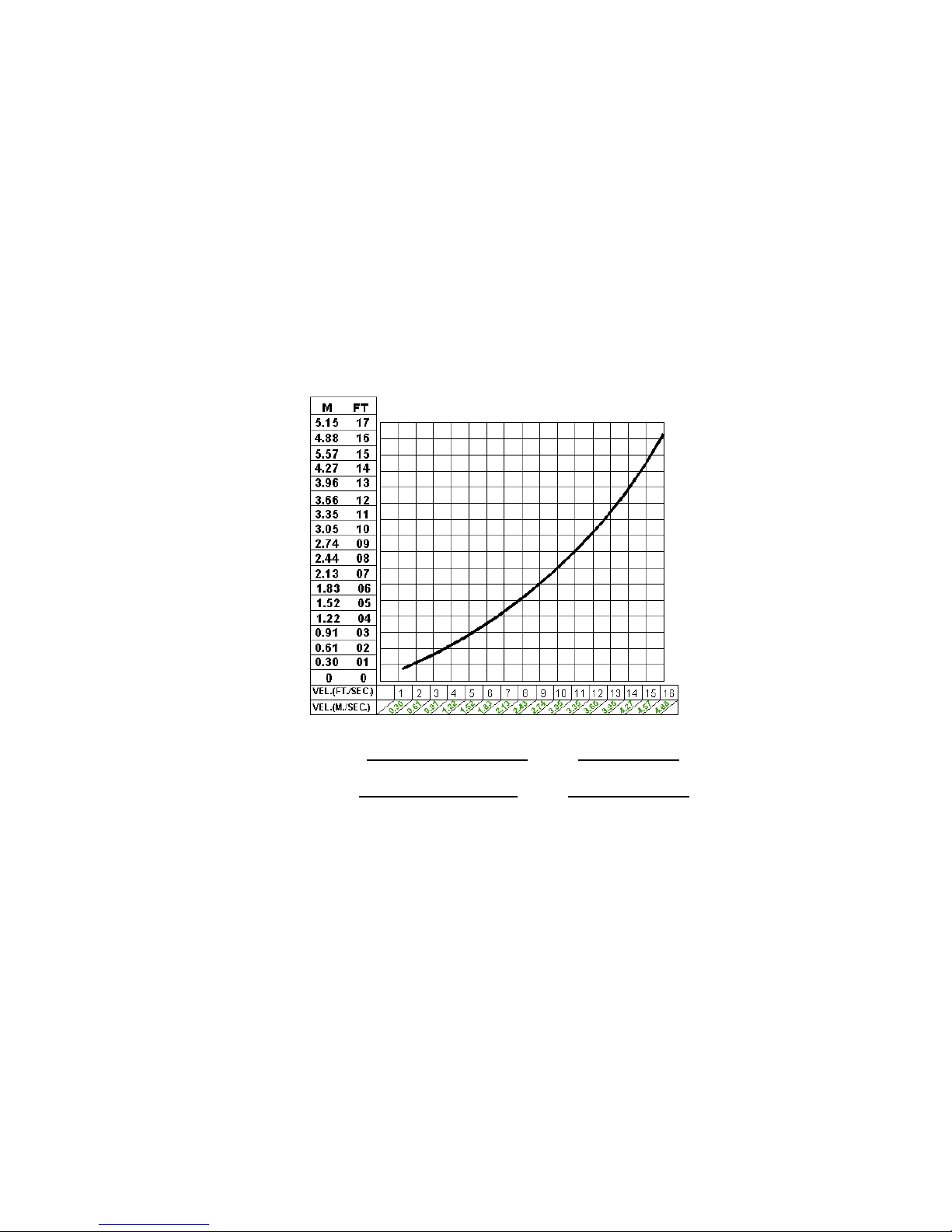
In low discharge head applications (less than 30
feet or 9 meters), it is recommended that the bypass
line be run back to the wet well, and locate 6 inches
below the water level or cut-off point of the level
pump. In some installations, this bypass line may be
terminated with a six-to-eight foot length of 1 ¼ inch
ID. smooth-bore hose; air and liquid vented during
the priming process will then agitate the hose and
break up any solids, grease, or other substances
likely to cause clogging.
CAUTION!
A bypass line that is returned to a wet well mus
t
be secured against being drawn into the pump
suction inlet.
It is also recommended that pipe unions be installed
at each 90º elbow in a bypass line to ease
disassembly and maintenance.

10
The valve will remain closed, reducing the bypass
of liquid to 1 to 5 gallons (3.8 to 19 liters) pe
r
minute, until the pump loses its prime or stops.
WARNING!
Some leakage (1 to 5 gallons [3.8 to 19 liters] per
minute) w ill occur w hen the valve is fully closed.
Be sure the bypass line is directed back to the
wet well or tank to prevent hazardous spills.
When the pump shuts down, the spring returns the
diaphragm to its original position. Any solids that
may have accumulated in the diaphragm chamber
settle to the bottom and are flushed out during the
next priming cycle.
NOTE
The valve will remain open if the pump does not
reach its designed capacity or head. Valve
closing pressure is dependent upon the
discharge head of the pump at full capacity. The
range of the valve closing pressure is
established by the tension rate of the spring as
ordered from the factory. Valve closing pressure
can be further adjusted to the exact system
requirements by moving the spring retaining pin
up or down the plunger rod to increase or
decrease tension on the spring. Contact your
Bombas Esco distributor or Bombas Esco
Company for information about an Automatic Air
Release Valve for your specific application.
Air Release Valve installation
The Automatic Air Release Valve must be
independently mounted in a horizontal position and
connected to the discharge line of the self-priming
centrifugal pump (see Figure 5).
NOTE
If the Air Release Valve is to be installed on a
staged pump application, contact the factory for
specific installation instructions.
AUTOMATIC AIR RELEASE VALVE
When properly installed and correctly adjusted to the
specific hydraulic operating conditions of the
application, the Bombas Esco Automatic Air Release
Valve will permit air to escape through the bypass line,
and then close automatically when the pump is fully
primed and pumping at full capacity.
Theory of Operation
Figures 3 and 4 show a cross-sectional view of the
A
utomatic Air Release Valve, and a corresponding
description of operation.
Figure 3. Valve in Open Position
During the priming cycle, air from the pump casing
flows through the bypass line, and passes through the
Air Release valve to the wet well (Figure 3).
Figure 4. Valve in Closed Position
When the pump is fully primed, pressure resulting from
flow against the valve diaphragm compresses the
spring and closes the valve (Figure 4).

11
Figure 5. Typical Automatic Air Release Valve Installation
The valve inlet must be installed between the pump
discharge port and the non-pressurized side of the
discharge check valve. The valve inlet is it at the
large end of the valve body, and is provided with
standard 1-inch NPT pipe threads.
The valve outlet is located at the opposite end of the
valve, and is also equipped with standard 1-inch NPT
pipe threads. The outlet should be connected to a
bleed line which slopes back to the wet well or sump.
The bleed line must be the same size as the inlet
piping, or larger. If piping is used for the bleed line,
avoid the use of elbows whenever possible.
NOTE
It is recommended that each Air Release Valve b
e
fitted with an independent bleeder line directe
d
back to the wet well. However, if multiple ai
r
Release Valves are installed in a system, th
e
bleeder lines may be directed to a commo
n
manifold pipe. Contact your Bombas Esc
o
distributor or the Bombas Esco company fo
r
information about installation of an Automatic Ai
r
Release Valve for your specific application.
ALIGNMENT
The alignment of the pump and its power source is
critical for trouble-free mechanical operation. In
either a flexible coupling or V-belt driven system, the
driver and pump must be mounted so that their
shafts are aligned with and parallel to each other. It
is imperative that alignment be checked after the
pump and piping are installed, and before operation.
NOTE
Check Rotation, Section C, before alignment of the
pump.
When mounted at the Bombas Esco factory, driver
and pump are aligned before shipment.
Misalignment will occur in transit and handling.
Pumps must be checking alignment, tighten the
foundation bolts. The pump casing feet and/or
pedestal feet, and the driver mounting bolts should
also be tightly secured.
SUCTION
LINE
WET WELL OR SUMP
BLEED LINE 1"
(25,4MM) DIA. MIN.
(CUSTOMER
FURNISHED)
EXTEND 6"
(152,4MM)
BELOW LIQUID
LEVEL SURFACE
90 LONG
RADIUS
ELBOW
°
INSTALL AIR RELEASE VALVE
IN HORIZONTAL POSITION
CLEAN-OUT
COVER
DISCHARGE PIPE
DISCHARGE PIPE
SUPPORT
BRACKET
SELF-PRINING
CENTRIFUGAL
PUMP
DRAIN LINE

12
Figure 6A. Aligning Spider – Type Couplings
F
Figure 6B. Aligning Non-Spider Type Couplings
WARNING!
When checking alignment, disconnect the power source
to ensure that the pump will remain inoperative.
CAUTION!
Adjusting the alignment in one direction may alter the
alignment in another direction. Check each procedure
after altering alignment.
Coupled Drives
When using couplings, the axis of the power source
must be aligned the axis of the pump shaft in both
the horizontal and vertical planes. Most couplings
require a specific gap or clearance between the
driving and the driven shafts. Refer to the coupling
manufacturer’s service literature.
A
lign spider insert type couplings by using calipers
to measure the dimensions on the circumference of
the outer ends of the coupling hub every 90
degrees. The coupling is in alignment when the hub
ends are the same distance apart at all points (see
Figure 6A).
Align non-spider type couplings by using a feele
r
gauge or taper gauge between the coupling halves
every 90 degrees. The coupling is in alignment when
the hubs are the same distance apart at all points
(see Figure 6B).
Check parallel adjustment by laying a straightedge
across both coupling rims at the top, bottom, and
side. When the straightedge rests evenly on both
halves of the coupling, the coupling is in horizontal
parallel alignment. If the coupling is misaligned use a
feeler gauge between the coupling and the
straightedge to measure the amount of misalignment.
V-Belt Drives
When using V-belt drives, the power source and the
pump must be parallel. Use a straightedge along the
sides of the pulleys to ensure that the pulleys are
properly aligned (see Figure 6C). In drive systems
using two pr more belts, make certain that the belts
are a matched set; unmatched sets will cause
accelerated belt wear.

13
MISALIGNED: SHAFTS MISALIGNED: SHAFTS ALIGNED: SHAFTS PARALLEL
NOT PARALLEL NOT IN LINE AND SHEAVES IN LINE
Figure 6C. Alignment of V-Belt Driven Pumps
F
Tighten the belts in accordance with the belt
manufacturer’s instructions. If the belts are too loose,
they will slip; if the belts are too tight, there will be
excessive power loss and possible bearing failure.
Select pulleys that will match the proper speed ratio;
over speeding the pump may damage both pump and
power source.
DANGER!
Do not operate the pump without the guard in
place over the rotating parts. Exposed rotating
parts can catch clothing, fingers, or tools,
causing severe injury to personnel.

14
OPERATION – SECTION C
Review all SAFET Y information in Section A.
Follow instructions on all tags, labels and decals
attached to the pump.
WARNING!
This pump is designed to handle mild
industrial corrosives, mud or slurries
containing large entrained solids. Do not
attempt to pump volatile; corrosive, or
flammable liquids w hich may damage the
pump or endanger personnel as a result of
pump failure.
CAUTION!
Pump speed and operating conditions must be
within the performance range shown on page
21.
PRIMING
Install the pump and piping as describe in
INSTALLATION. Make sure that the piping
connections are tight, and that the pump is
securely mounted. Check that the pump is
properly lubricated (see LUBRICATION in
MAINTENANCE AND REPAIR).
This pump is self-priming, but the pump should
never be operated unless there is liquid in the
pump casing.
CAUTION!
Never operate this pump unless there is liquid
in the pump casing. The pump will not prime
w hen dry. Extend operation of a dry pump w ill
destroy the seal assembly.
Add liquid to the pump casing when:
1. The pump is being put into service for the
first time.
2. The pump has not been used for a
considerable length of time.
3. The liquid in the pump casing has
evaporated.
Once the pump casing has been filled, the pump
will prime and reprime as necessary.
WARNING!
After filling the pump casing, reinstall and
tighten the fill plug. Do not attempt to operate
the pump unless all connecting piping is
securely installed. Otherwise, liquid in the
pump forced out under pressure could cause
injury to personnel.
To fill the pump, remove the pump casing fill cover
or fill plug in the top of the casing, and add clean
liquid until the casing is filled. Replace the fill cover
or fill plug before operating the pump.
STARTING
Consult the operations manual furnished with the
power source.
Rotation
The correct direction of pump rotation is
counterclockwise when facing the impeller. The
pump could be damaged and performance
adversely affected by incorrect rotation. If pump
performance is not within the specified limits (see
the curve on page 21), check the direction of
power source rotation before further
troubleshooting.
If an electric motor is used to drive the pump,
remove V-belts, couplings, or otherwise disconnect
the pump from the motor before checking motor
rotation. Operate the motor independently while
observing the direction of the motor shaft, or
cooling fan.

15
If rotation is incorrect on a three-phase motor,
have a qualified electrician interchange any of the
Phase wires to change direction. If rotation is
incorrect on a single-phase motor, consult the
literature supplied with the motor for specific
instructions.
OPERATION
Lines With a Bypass
If a Bombas Esco Automatic Air Release Valve
has been installed, the valve will automatically
open to allow the pump to prime, and
automatically close after priming is complete (see
INSTALLATION for Air Release Valve operation.
Lines Without a Bypass
Open all valves in the discharge line and start the
power source. Priming is indicated by a positive
reading on the o the discharge pressure gauge or
by a quieter operation. The pump may not prime
immediately because the suction line must first fill
with liquid. If the pump fails to prime within five
minutes, stop it and check the suction line for
leaks.
After the pump has been primed, partially close
the discharge line throttling valve in order to fill the
line slowly and guard against excessive shock
pressure which could damage pipe ends, gaskets,
sprinkler heads, and any other fixtures connected
to the line. When the discharge line is completely
filled, adjust the throttling valve to the required
flow rate.
WARNING!
Do not operate the pump against a closed
discharge throttling valve for long periods of
time. If operated against a closed discharge
throttling valve, pump components will
deteriorate, and the liquid could come to a
boil, build pressure, and cause the pump
casing to rupture or explode.
Leakage
No leakage should be visible at pump mating
surfaces, or at pump connections or fittings. Keep
all line connections and fittings tight to maintain
maximum pump efficiency.
Liquid Temperature And Overheating
The maximum liquid temperature for this pump is
160º F (71º C). Do not apply it at a higher
operating temperature.
Overheating can occur if operated with the valves
in the suction or discharge lines closed. Operating
against closed valves could bring the liquid to a
boil, build pressure, and cause the pump to rupture
or explode. If overheating occurs, stop the pump
and allow it to cool before servicing it. Refill the
pump casing with cool liquid.
DANGER!
Allow an over-heath pump to cool before
servicing. Do not remove plates, covers,
gauges, or fittings from an overheated pump.
Liquid within the pump can reach boiling
temperatures, and vapor pressure within the
pump can cause parts being disengaged to be
ejected, with great force. After the pump cools,
drain the liquid from the pump by removing the
casing drain plug. Use caution when removing
the plug to prevent injury to personnel from hot
liquid.
As safeguard against rupture or explosion due to
heat, this pump is equipped with a pressure relief
valve which will open if vapor pressure within the
pump casing reaches a critical point. If overheating
does occur, stop the pump immediately and allow it
to cool before servicing it. Approach any
overheated pump cautiously. It is recommended
that the pressure relief valve assembly be replaced
at each overhaul, or any time the pump casing
overheats and activates the valve. Never replace
this valve with a substitute which has not been
specified or provided by the Bombas Esco
Company.

16
Strainer Check
If s suction strainer has been shipped with the
pump or installed by the user, check the straine
r
regularly, and clean it as necessary. The straine
r
should also be checked if pump flow rate begins
to drop. If a vacuum suction gauge has been
installed, monitor and record the readings
regularly to detect strainer blockage.
Never introduce air or steam pressure into the
pump casing or piping to remove a blockage. This
could result in personal injury or damage to the
equipment. If back flushing is absolutely
necessary, liquid pressure must be limited to 50%
of the maximum permissible operating pressure
show on the pump performance curve.
Pump Vacuum Check
With the pump inoperative, install a vacuum
gauge in the system, using pipe dope on the
threads. Block the suction line and start the pump.
A
t operating speed the pump should pull a
vacuum of 20 inches (508,0mm) or more of
mercury. If it does not, check for air leaks in the
seal, gasket, or discharge valve.
Open the suction line, and read the vacuum
gauge with the pump primed and at operation
speed. Shut off the pump. The vacuum gauge
reading will immediately drop proportionate to
static suction lift, and should then stabilize. If the
vacuum reading falls off rapidly after stabilization,
an air leak exists. Before checking for the source
of the leak, check the point of installation of the
vacuum gauge.
STOPPING
Never halt the flow of liquid suddenly. If the liquid
being pumped is stopped abruptly, damaging
shock waves can be transmitted to the pump and
piping system. Close all connecting valves slowly.
On engine driven pumps, reduce the throttle
speed slowly and allow the engine to idle briefly
before stopping.
CAUTION!
If the application involves a high discharge head,
gradually close the discharge throttling valve
before stopping the pump.
After stopping the pump, lock out or disconnect the
power source to ensure that the pump will remain
inoperative.
WARNING!
Do not operate the pump against a closed
discharge throttling valve for long periods of
time. If operated against a closed discharge
throttling valve, pump components w ill
deteriorate, and the liquid could come to a boil,
build pressure, and cause the pump casing to
rupture or explode.
Cold Weather Preservation
In below freezing conditions, drain the pump to
prevent damage from freezing. Also, clean out any
solids by flushing with a hose. Operate the pump
for approximately one minute; this will remove any
remaining liquid that could freeze the pump
rotating parts. If the pump will be idle for more than
a few hours, or if it has been pumping liquids
containing a large amount of solids, drain the
pump, and flush it thoroughly with clean water. To
prevent large solids from clogging the drain port
and preventing the pump from completely draining,
insert a rod or stiff wire in the drain port, and
agitate the liquid during the draining process.
Clean out any remaining solids by flushing with a
hose.
BEARING TEMPERATURE CHECK
Bearings normally run at higher than ambient
temperatures because of heat generated by
friction. Temperatures up to 160º F(71º C) are
considered normal for bearings, and they can
operate safely to at least 180º F(82º C).

17
Checking bearing temperatures by hand is
inaccurate. Bearing temperatures can be
measured accurately by placing a contact-type
Thermometer against the housing. Record this
temperature for future reference.
A sudden increase in bearing temperature is a
warning that the bearings are at the point of failing
to operate properly. Make certain that the bearing
lubricant is of the proper viscosity and at the
correct level (see LUBRICATION in
MAINTENANCE AND REPAIR).
Bearing overheating can also be caused by shaft
misalignment and/or excessive vibration.
When pumps are first started, the bearings may
seem to run at temperatures above normal.
Continued operation should bring the temperatures
down to normal levels.

18
TROUBLESHOOTING - SECTION D
Review all SAFET Y information in Section A.
TROUBLE POSSIBLE CAUSE PROBABLE REMEDY
PUMP FAILS
TO PRIME
Not enough liquid in casing.
Suction check valve contaminated or
damaged.
Air leak in suction line.
Lining of suction hose collapsed.
Leaking or worn seal or pump gasket.
Suction lift or discharge head too high.
Strainer clogged.
Add liquid to casing. See PRIMING.
Clean or replace check valve.
Correct leak.
Replace suction Hose.
Check pump vacuum. Replace leaking
Or worn seal or gasket.
Check piping installation and install bypass line if
needed. See INSTALLATION.
Check strainer and clean if necessary.
WARNING!
Before attempting to open or service the
pump:
1. Familiarize yourself w ith this manual.
2. Lock out or disconnect the pow er
source to ensure that the pump w ill
remain inoperative.
3. Allow the pump to cool if overheated.
4. Check the temperature before opening
any covers, plates, or plugs.
5. Close the suction and discharge valves.
6. Vent the pump slowly and cautiously.
7. Drain the pump.

19
TROUBLE POSSIBLE CAUSE PROBABLE REMEDY
PUMP STOPS OR
FAILS TO DELIVER
RATED FLOW OR
PRESSURE
Air leak in suction line.
Lining of suction hose collapsed.
Leaking or worn seal or pump gasket.
Strainer clogged.
Suction intake not submerged at
proper level or sump too small.
Impeller or other wearing parts worn or
damaged.
Impeller clogged.
Pump speed too slow.
Discharge head too high.
Suction lift too high.
Correct leak.
Replace suction hose.
Check pump vacuum. Replace leaking or
worn seal or gasket.
Check strainer and clean if necessary.
Check installation and correct submergence
as needed.
Replace worn or damaged parts. Check
that impeller is properly centered and
rotates.
Free impeller of debris.
Check driver output; check belts or couplings
for slippage.
Install bypass line.
Measure lift w/vacuum gauge. Reduce lift
and/or friction losses in suction line.
PUMP REQUIRES
TOO MUCH POWER
Pump speed too high
Discharge head too low.
Liquid solution too thick.
Bearing(s) frozen.
Check driver output; check that sheaves or
motor rpm are correctly sized.
Adjust discharge valve.
Dilute if possible.
Disassemble pump and check bearing(s).
PUMP CLOGS
FREQUENTLY
Liquid solution too thick.
Discharge flow too slow.
Suction check valve or foot valve
Clogged or binding.
Dilute if possible.
Open discharge valve fully to increase flow
rate, and run power source at maximum
governed speed.
Clean valve.
Table of contents
Other Esco Water Pump manuals
Popular Water Pump manuals by other brands

Baron
Baron BA-2620RD instructions

GORMAN-RUPP
GORMAN-RUPP SF6D Installation, operation, and maintenance manual with parts list

JTS
JTS PCP HAND PUMP manual

World Chemical
World Chemical SUBMERSE YD-5002GWN1-HP instruction manual

Loctite
Loctite 988530 Operation manual

MULTIQUIP
MULTIQUIP P200DLST Operation manual

KSB
KSB Vitachrom Installation & operating manual

GORMAN-RUPP PUMPS
GORMAN-RUPP PUMPS 10 Series Installation, operation and maintenance manual

Anest Iwata
Anest Iwata ISP-250E instruction manual

Zoeller
Zoeller QWIK JON ULTIMA 202 installation instructions

Everbilt
Everbilt SSB300 Use and care guide

Fubag
Fubag PG 600 Operator's manual