ESDEC Panelclaw clawFR Dual User manual

9910046 RevG April 2021
Table of Contents
clawFR Dual Tilt 10 Degree
Installation Manual
ANSI/UL 2703
System Fire Class Rating: Class A for low slope roofs with Type 1, 2, 16, 19, 22, 25, 29 and 30 Modules
Mechanical Load Rating: See Appendix A: UL 2703 Grounding
Introduction & Safety Overview 2
Storage, Array Construction, and
O&M considerations
3
System Components 4
Accessories 5
Tools, Torque, & Construction Aid 6
Construction Aid Setup 7
Build Assemblies 8
Build East Edge Row 9
Build Remaining Rows 10
Place Ballast 11
Install Module Low Side 13
Install Module High Side 15
Continue Installing Modules 16
Cam & Lock Claw Inspection 17
Electrical Grounding 18
Appendix 19
Scan here for
installation
videos
9910046 RevG April 2021
Introduction
The clawFR DT 10 Degree flat roof mounting system is comprised
of four major components that intuitively assemble into a support
structure for photovoltaic (PV) modules.
This installation manual explains how to build a PV array using
clawFR DT 10 Degree.
PAGE 2
A CORROSION INSPECTION ONE YEAR AFTER INSTALLATION
AND ONCE EVERY THREE YEARS THEREAFTER IS REQUIRED
TO MAINTAIN THE PRODUCT WARRANTY. VISIBLE SURFACE
RED RUST ON STEEL COMPONENTS MUST BE LOCALLY
COATED WITH A COMMERCIALLY AVAILABLE GALVANIZED
PAINT OR COATING TO MAINTAIN PRODUCT WARRANTY.
EXCEPT FOR DEFLECTORS, ALL RACKING COMPONENTS IN
EACH SUBARRAY AND THEIR CONNECTIONS, BALLAST, AND
MECHANICAL ATTACHMENTS (IF ANY IN DESIGN) MUST BE
INSTALLED BEFORE MOUNTING MODULES. WHEN
FORECASTED WIND GUSTS EXCEED 25%OF THE WIND
SPEED LISTED IN THE SITE CRITERIA TABLE OF THE RACKING
CONSTRUCTION SET, DEFLECTORS MUST BE INSTALLED ON
ALL MOUNTED MODULES TO AVOID POSSIBLE SYSTEM
DAMAGE.
Safety Overview
Safety is an essential part of every PV installation and every
construction site. It is imperative to plan ahead for any safety
concerns and hazards to promote safe work practices during
installation. This section does not claim to address or support all
safety concerns that may arise during the installation of PanelClaw
mounting systems or any other aspect of the work being
performed. Before beginning work, installers should refer to all
local and federal safety, health, and regulatory requirements to
assure compliance. Refer to OSHA Part 1926 and its related
Subparts for federal construction related regulations and
standards.
Appendix J: Safety outlines some of the major hazards to be aware
of during the installation of PanelClaw products.
PRIOR TO INSTALLATION, READ THE SAFETY PROVISIONS
ATTACHED IN Appendix J: Safety AND REVIEW THIS
INSTALLATION MANUAL IN ITS ENTIRETY.

9910046 RevG April 2021 PAGE 3
Storage Considerations
PanelClaw recommends installing the racking components shortly
after delivery to the project site. If clawFR components are not
deployed immediately, they should be stored in a well-ventilated,
dry location. Otherwise, moisture can form between the packed
components which may cause staining and/or white rust.
Significant white rust formation may decrease the coating service
life and, in extreme cases, the component performance.
If storage onsite is unavoidable, remove the plastic and/or
carboard wrapping from the exterior of the packaging and cover
with canvas or place components under an open sided tent. Note
the use of a plastic cover does more harm than good as it prevents
the product from breathing and causes condensation. Storing parts
in any other manner is at the customer’s own risk. PanelClaw is not
liable for claims related to improper storage and any such claims
are not covered by the product warranty. Operations & Maintenance
See O&M Manual, available upon request, for initial inspection
recommendations including steps that can be performed only
during construction.
Sub Array Dimensions
Each PV system is unique and is frequently made up of multiple
sub arrays. The Racking Construction Set, which must be onsite at
all times during construction, details sub array dimensions and
location on the roof. Review the Racking Construction Set in its
entirety to prevent unnecessary rework during site construction.
The furthest extent of the racking components or modules of
adjacent sub arrays, whichever defines the outermost array
boundaries, must be separated by at least the minimum
dimensions documented in the Racking Construction Set. Refer to
the general notes and the Minimum Clearance Requirements
table, if present, within the Racking Construction Set.
9910046 RevG April 2021
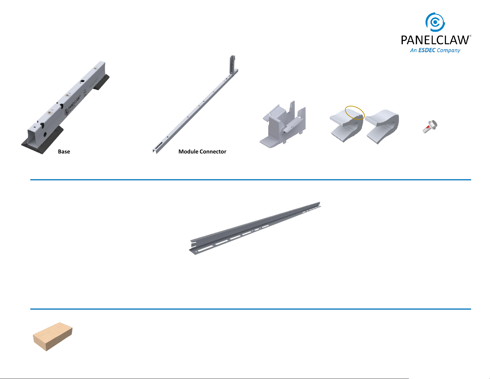
System Components
PAGE 4
M6x16mm Bolt
2000697
Module Connector
5000507XX
Base
500050201
Rail
2000695/2000895
Cam Claw*
2000673 (1 pair of grooves)
2000815 (1 groove)
Pair of grooves
*Both SKUs are shown here. Check the Racking Construction Set to verify correct Cam Claw is received
Cam
5000500
Ballast Block: Solid cap concrete roof paver, conforms to ASTM C1491 or C1884 standard and manufactured for
freeze-thaw resistance where applicable. See Appendix E for more details

9910046 RevG April 2021
Accessories
PAGE 5
Note: Use of non-UL listed accessories, including non-metallic components, does not affect the system ANSI/UL 2703 certification.
See: Appendices D-H
Shim Pad
5000228
Optimizer Attachment
5000509
Wire Router
5000225XX
Base Pad
2000678
Wire Clip
5000226
Lock Claw Clip
2000819
Wire Management Accessories
See: 9910053-Wire Management Manual
Mechanical Attachment Strut
2000830/2000930
Mechanical Hardware Kit
500022301/5000423
Ground Lug Kit
5000494
WM Homerun
200082302
and 2000828
WM Homerun
Clip
WM Homerun
Cover

9910046 RevG April 2021
Torque Setting
*
Fastening Operation
6 ft
-lb (8.1 Nm)
All System connections
except
Special Cases
Spacer Stick
Construction Aids
Drill with Inline-Torque Limiter or Torque Wrench
10 mm Magnetic Nut Driver
ALERT: NO IMPACT DRIVERS
Tools
Cam Spacer / Lock Claw Insertion Depth Gauge
*+/-4% allowable during installation
PAGE 6
Spacer Stick and Cam Spacer Kit
5000510/5000610
2000761 may be required
Note: Additional tools may be required when installing
accessories.
Bolts which are installed into a pre-installed nut
are tightened to 6 ft-lb
9910046 RevG April 2021
1. Construction Aid Setup
2X
3X
1X
5X
Tip: L, S, and Cam Spacer dimensions are found in the
Racking Construction Set. See Sheet Title: Typical Array
Dimensions.
1.1 Assemble the Spacer Stick and adjust to L & S dimensions.
All dimensions are measured from the Base centerlines.
Tip: To stiffen the Spacer Stick, place one Rail
2000695/2000895 on the assembly as shown, shift the
Rail to find a location which allows for attachment with
the specified bolts. Tighten the bolts.
1.2 Insert the bolt and adjust the Cam Spacer to the Cam
Spacing dimension.
Adjust Spacer Stick
Spacing S
Spacing L
PAGE 7
Typical Cam
Spacer Usage
1X Rail 2000695/2000895
The optional 2000761 center
piece is used only if 5000610 is
shipped and the Racking
Construction set calls for
750mm “S” spacing.
Cam Spacer / Lock Claw
Insertion Depth Gauge
Cam
Spacing
9910046 RevG April 2021
Hole 2
West Module
Assembly
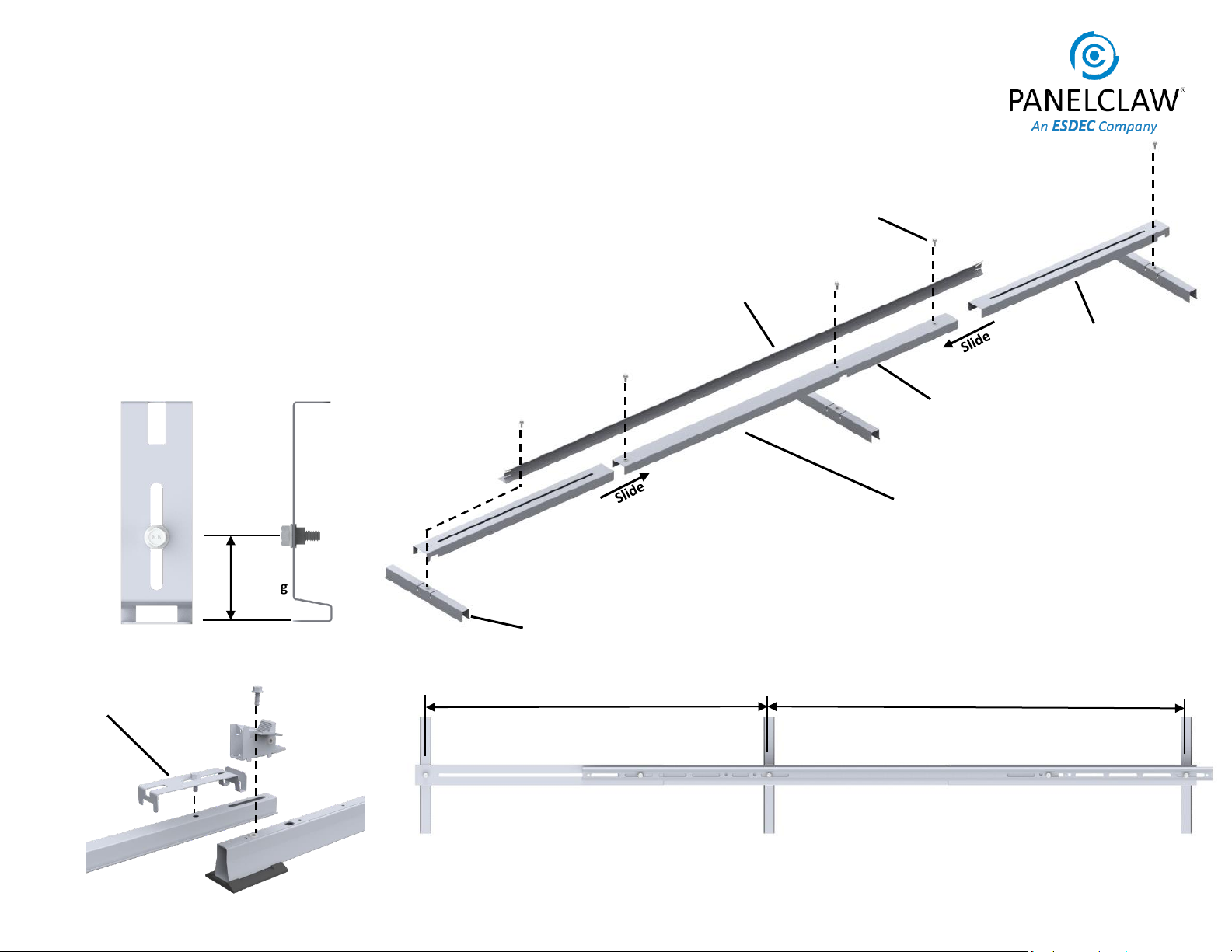
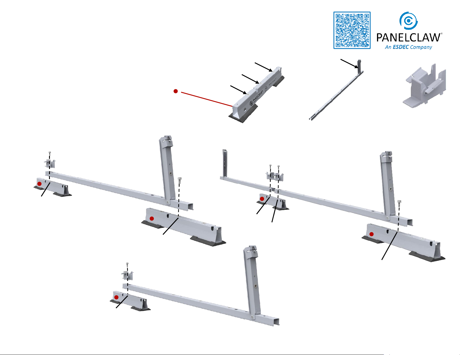
2. Build Assemblies
PAGE 8
2.1 Position components as required per assembly type and loosely
assemble the Cam, Module Connector and Base.
ALERT: Note location of orientation marker on Base “ ”
Tip: Immediately tighten bolts to 6 ft-lb which are at the Tilt Arm
end of the assembly.
2.2 Use the Cam Spacer tool to correctly locate the Module Connector.
Tighten bolt to 6 ft-lb.
Middle Valley
Assembly
Hole 2
Hole 1
Hole 2
Hole 2
East Module
Assembly
Hole 2
+ +
Base
(qty 1 or 2) Module Connector Cam
Hole 1
Hole 3
Hole 2
Tilt Arm
Scan here for
Assembly Jig
Manual

9910046 RevG April 2021 PAGE 9
3. Build East Edge Row
S
LSpacer Stick
S
LALERT: To ensure system
alignment, use the Spacer Stick
to align Module Connectors
before securing Rails.
Place East Module Assemblies with the Base Pads
along the East Edge line. The first and last East
Module Assemblies should be placed with the edge
of the Base Pads on the Base Edge line.
Tip: Raise Tilt Arms after securement of assembly.
3.2
Place a Rail on all “S” spacings (module centered).
Rails at row ends should be flush with array edge
when “S” spacings permits.
Place a Rail on all “L” spacings (between modules) on
top of and overlapping the Rails on the “S” spacing.
Install bolt and tighten to 6ft-lb.
S
L
3.3
Base edge
measured to
Pad edge
Tip: Base Edge
is in line with
Base Pad
Tip: “S” spacings are module centered
“L” spacings are between modules.
Tip: L, S, R and AEBE dimensions
are found in the Racking
Construction Set. See Sheet
Title: Typical Array Dimensions.
Snap East Edge, Array Edge, and Base Edge lines.
Tip: Snap Array Edge lines on one or both array
edges (row ends) and snap Base Edge line on the
edge where module mounting will begin.
3.1
See Sheet Title Page: Typical
Array Dimensions in the Racking
Construction Set for AEBE
dimension.
Scan here for
rail installation
video
ALERT: Rail on “L” Spacing is ALWAYS on
top of Rail on “S” Spacing. This
installation sequence is critical to system
performance.
Tip: Rail has two holes. Consult Sheet
Title: Typical Array Dimensions in the
Racking Construction Set for appropriate
hole use.

9910046 RevG April 2021
4.2 Install Rails throughout the array using the same
steps described on the previous page. Alternating
between “S” and “ L” Spacings. Install bolt and
tighten to 6 ft-lb.
ALERT: To ensure system alignment, use the Spacer
Stick to align Module Connectors before securing
Rails.
PAGE 10
4. Build Remaining Rows
Place Middle Valley or West assemblies onto
assemblies from previous row and bolt to 6 ft-lb.
Tip: Sheet Title: Assemblies in the Racking
Construction Set clearly indicates hole selection.
Using the wrong hole will result in an array which
does not match site plan.
4.1
Note
Orientation
ALERT: Eastern and Western Edge Rails face the
opposite direction; bolts securing these rails are
tightened to 6ft-lb.
Hole 1
Hole 1
Rail are required at Eastern
and Western Array Edges
ALERT: Installation of Eastern and Western Array
Edge Rails is critical to system performance.
ALERT: Tighten fasteners prior to moving spacer
stick to next position.
Spacer Stick
L
Tip: Raise Tilt Arms after
bolting assemblies in
preparation for Rail
installation.
S

9910046 RevG April 2021
ALERT: Do not step
on ballast blocks
Attach Rail to
location closest
to Cam.
Rail Position for 5-8 Ballast blocks
PAGE 11
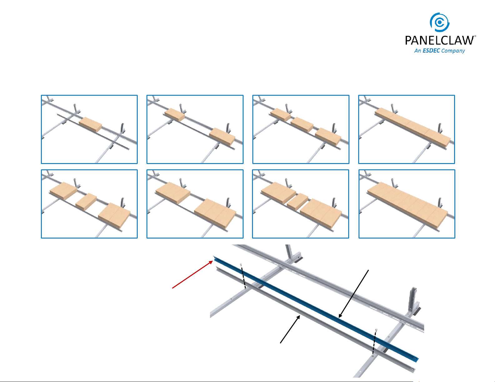
5. Place Ballast
Tip: Installing the east edge row ballast blocks helps keep the
racking structure from moving as the rest of the array is built.
Tip: Sheet Title: Ballast Layout –XX in the Racking Construction
Set identifies where Ballast is to be installed. Mark the roof with
chalk to speed up installation.
5.1 Install a Rail onto array in locations where Ballast is required.
Bolt to both Module Connectors and tighten to 6 ft-lb.
ALERT: Every Rail must be fastened to two Module Connector
assemblies.
Tip: Ballast and Rails are only placed on “S” spacings. Center
them on the “S” spacing for equal ballast distribution.
5.2 Place Ballast onto Rails. If rapid cyclic movement of system is
expected e.g. due to seismic activity or building vibration from
activities within or nearby the structure, bend the Rail tabs to
secure Ballast.
ALERT: Install Mechanical Attachments before going to next
step. See Appendix D
Rail Position for 1-4 Ballast blocks
Attach Rail to
location closest to
Tilt Arm.
Bend tabs at ends of Rail.
(See 5.2 to determine if required)
Bend Tabs to
capture Ballast
as required.
1
2
5
8
4
Ballast Quantity
S
3
7
6
9910046 RevG April 2021 PAGE 12
5. Place Ballast (Continued)
1 2 3 4
5 6 7* 8*
*ALERT: Modules longer than 2100 mm with
7 or 8 ballast blocks require two (2) Rails.
Install Rail 2 on top of Rail 1 and tighten to
6ft-lb.
Rail 1
Rail 2
5.3 Ballast must be placed as shown. Ballast quantity affects the Ballast placement on the Rails
and in some cases additional Rails are required as noted below.
9910046 RevG April 2021
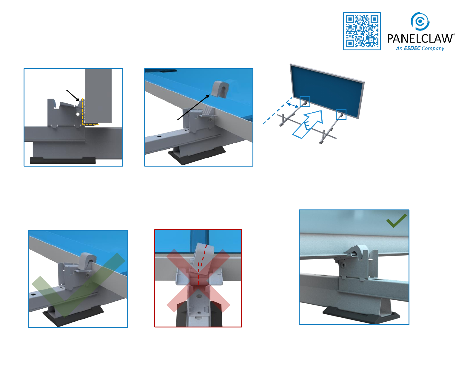
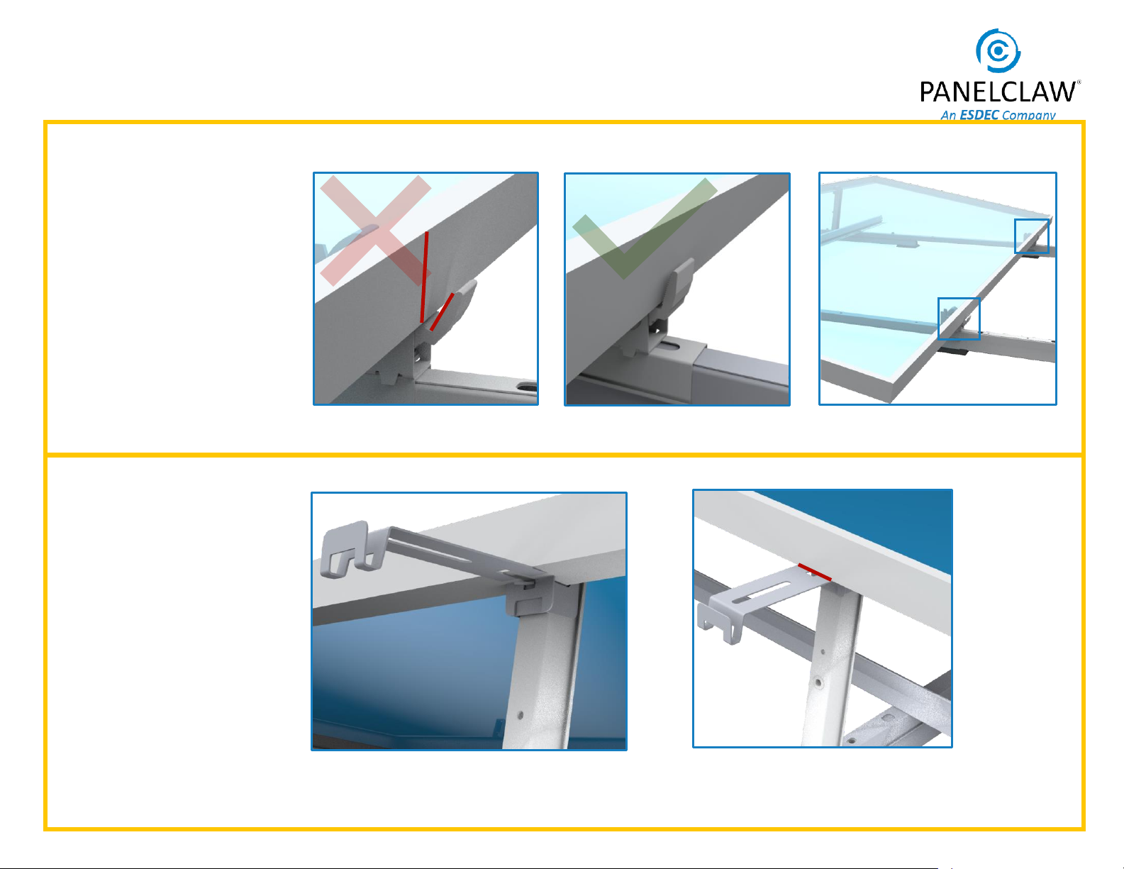
6. Install Module Low Side
PAGE 13
Cam Claw aligned
6.1
Cam Seat
Place module on Cam Seat and
align with Array Edge.
Tip: Ensure the module is vertical
and flush with Seat.
ALERT: Cam Claw is mis-aligned.
Cam Claw
Place Cam Claw over module flange.
Apply a small downward force to
make sure it is properly seated.
6.2
ALERT: Install Mechanical Attachments before installing modules.
See Appendix D
R
Tip: R dimension is found in
the Racking Construction Set.
See Sheet Title: Typical Array
Dimensions.
Tip: Installing all East facing
modules prior to installing
West facing modules leads to
faster system assembly.
ALERT: Do not leave modules in
vertical position, go immediately to
next installation step (high side install).
ALERT: When forecasted wind gusts exceed 25%of the wind
speed listed in the Site Criteria Table of the Racking
Construction Set, all mounted modules must be complete
pairs (Domes) to avoid system damage.
Example of a typical good Cam Claw install,
after the module has been rotated down
and high-side has been installed
Scan here for
module
installation
video
Tip: Cam Claw grooves may be
ignored for installation purposes
9910046 RevG April 2021
6. Install Module Low Side (Continued)
PAGE 14
If Cam flanges align with the module mounting holes,
Contact PanelClaw. Consult Sheet Title : Typical Array
Dimensions in the Racking Construction Set to verify that
appropriate R dimension is in use.
Cam flanges are located away from the module mounting
holes R
9910046 RevG April 2021
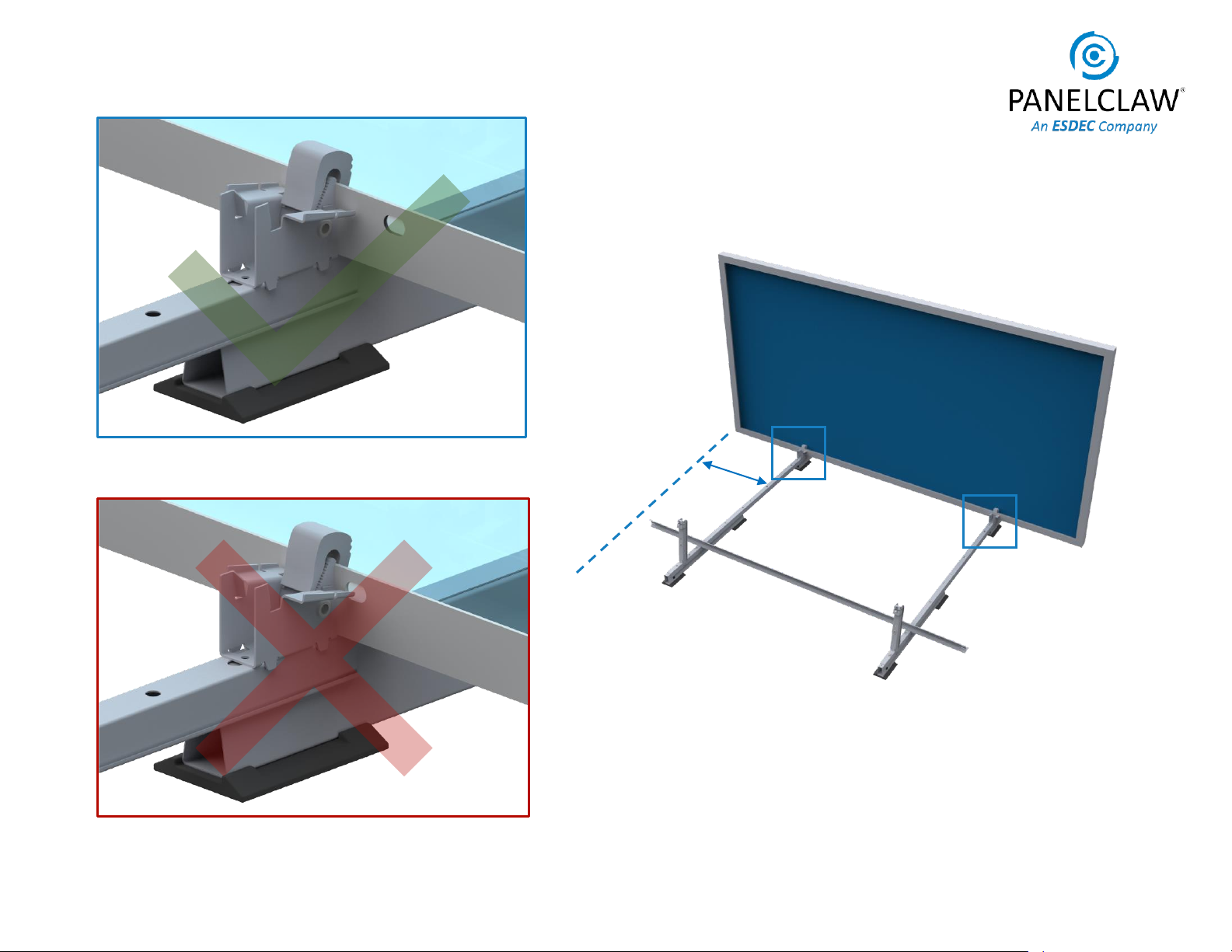
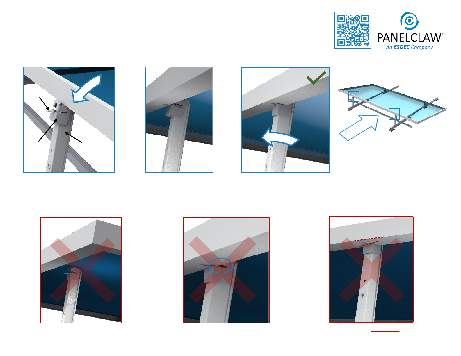
7. Install Module High Side
PAGE 15
DO NOT REST MODULE
BACKSHEET ON TILT ARM
Tip: Use two hands when engaging Lock
Claw to ensure correct installation.
LOCK CLAW UNEVENLY
ENGAGED
Tilt Arm
Tongue
Lock Claw
Rotate module down and rest the module
frame on the top of the Tilt Arms.
Tip: Make sure the Tilt Arms are fully
raised.
7.1
Support module while carefully
rotating the Tilt Arm just enough
to rest the module frame on the
Lock Claw tongue.
7.2
Pull the Tilt Arm forward until the Lock
Claw is fully engaged onto the module
frame flange.
7.3
LOCK CLAW NOT FULLY
ENGAGED
E
Tip: See Appendix I for Lock Claw
reset method.
Scan here for
module high
side installation
video

9910046 RevG April 2021 PAGE 16
7. Continue Installing Modules
ALERT: When forecasted wind gusts
exceed 25%of the wind speed listed
in the Site Criteria Table of the
Racking Construction Set, all
mounted modules must be complete
pairs (Domes) to avoid system
damage.
DOME
Use Cam Claw as spacer to set spacing between modules.
ALERT: Check the R
dimension every 5th
module and adjust
spacing between
modules as needed.
R
Tip: R dimension is found in the Racking Construction Set.
See Sheet Title: Typical Array Dimensions.
ALERT: If Cam Flanges are located on
Module mounting holes refer to
page 14 of the manual to verify
appropriate spacing.
9910046 RevG April 2021 PAGE 17
Lock Claw Insertion Gauge configuration and use
Place gauge against Lock Claw and underside
of module.
Select a Lock Claw which has been
confirmed to be installed correctly
through visual inspection.
The Tilt Arm and Lock Claw should
be aligned with the module frame
and the Lock Claw fully engaged
on the frame.
Mark line on gauge to finish setup.
Use gauge to confirm full Lock Claw
engagement-line must be visible.
8. Cam & Lock Claw Inspection
Inspect Cam side module connection
Module and Cam are near flush.
Module and Cam have a large
non-uniform gap.
Cam installation can be quickly visually
inspected (no gauge is available or
required) by comparing a known good
installation with all other installations.
Some gap between Module and Cam
is permissible. The graphics are
representative only; actual installation
geometry varies by module vendor
and part number. If it is not clear the
module low side connection is good,
contact PanelClaw for assistance.
ALERT: Verify correct installation by
lifting up on the module near the Cam
and making sure no movement occurs.

9910046 RevG April 2021
Electrical Grounding
Please consult with national and local building code(s) for
complete grounding requirements for your installation. The
clawFR grounding method conforms to ANSI/UL 2703 and is
certified by SolarPTL for use with approved photovoltaic
modules listed under ANSI/UL 1703 and/or ANSI/UL 61730.
Installers can quickly and easily establish ANSI/UL 2703
certified electric bonds between all connected array
components, including modules and mounting system
components, without the use of additional grounding
devices, e.g. ground lugs and copper wire. At least one
ground lug must be used to ground all strings within a
physical sub-array provided the fuse rating for each string
does not exceed 40 amps. Installers may opt to use multiple
lugs per sub-array for redundancy. When grounding devices
are installed according with the approved methodology and
capacity below, the connections described above meet all
the requirements outlined in NEC 690.43.
Grounding Instructions
For modules that have been evaluated for use with clawFR Dual Tilt 10
Degree, please follow the instructions below in Appendix A: UL 2703
Grounding. Additional information regarding ANSI/UL 2703 and the
specific list of evaluated modules included in PanelClaw’s UL listing can
be found in the “clawFR UL Overview and Module Listing” document
(available at www.panelclaw.com).
For modules that have not been evaluated for use with clawFR, please
contact PanelClaw
ALERT: During grounding and bonding ensure there is separation
between bare copper and aluminum or coated steel components.
PAGE 18

9910046 RevG April 2021
Appendix A: UL 2703 Grounding
The clawFR Dual Tilt 10 Degree flat roof
system may be used to ground and/or mount
aPV module complying with ANSI/UL 1703
or ANSI/UL 61730 only when the specific
module has been evaluated for grounding
and/or mounting in compliance with the
included instructions. For a list of modules
which have been evaluated see PanelClaw’s
“clawFR UL Overview and Module Listing”
(see www.panelclaw.com).
A periodic re-inspection of the system shall
be performed for loose components, loose
fasteners, and any corrosion. If found, they
should be immediately replaced or remedied
in accordance with the system installation
instructions.
System Ground Path
The system ground path “grid” is established throughout the array by the interconnection of system components. Specifically, in the column
direction via the Base and Module Connector connections and in the row direction via the Rail connections. A Tyco lug connected to the Rail
establishes a point of connection for the EGC at one location with a contiguous array. All modules are grounded to the system through their
Cam to Module connection.
Note: The presence of aPV module does not affect the bonding ability of the clawFR system components. More precisely, the grid provides
a means to ground PV Modules which have been evaluated for ANSI/UL 2703 grounding with clawFR.
PAGE 19
To DC
Grounding
Path
Ground Lug
Tyco #2106831-1
Row
Column
9910046 RevG April 2021
Appendix A: UL 2703 Grounding (Continued)
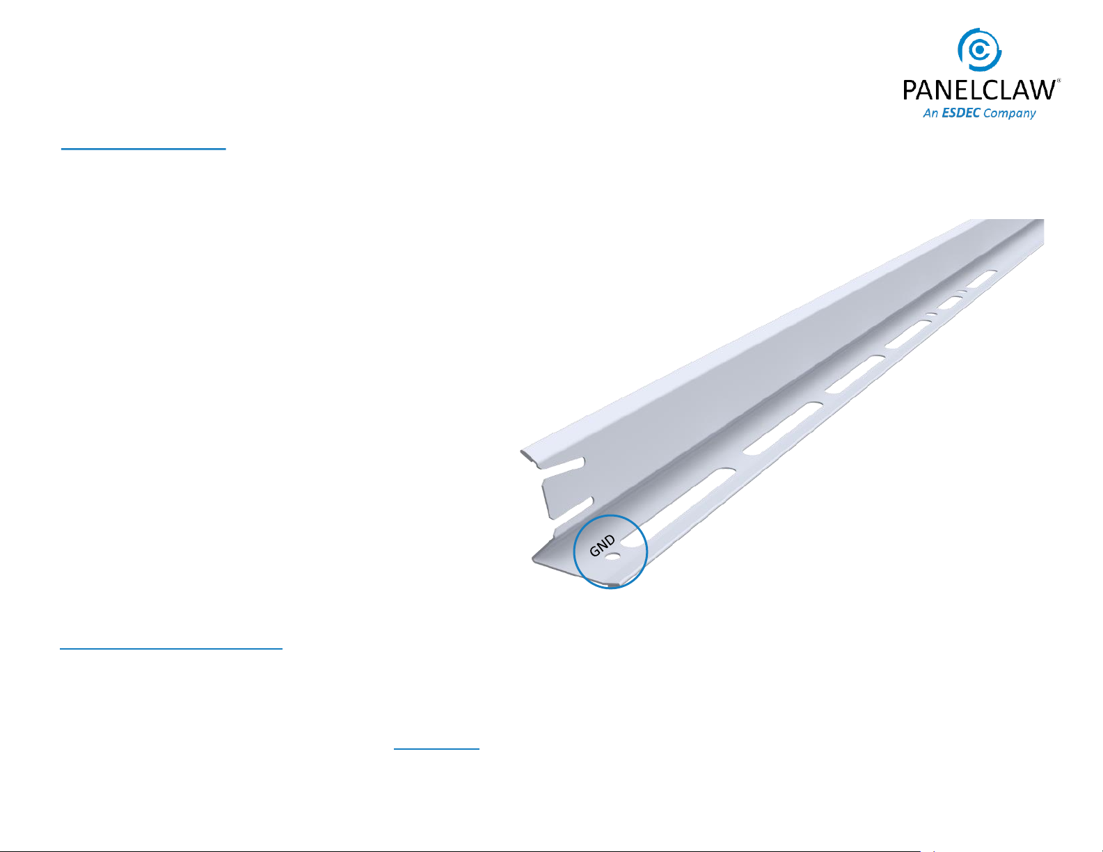
Tyco Grounding lug attachment:
To attach the Tyco grounding device/lug to the Rail, the mounting hex washer and threaded post end should be installed to the specified hole
in the Rail and torqued to 2.08 ft-lb (25 in-lb).Once the grounding device/lug has been attached to the Rail, a copper bonding jumper from an
acceptable DC grounded location outside of the array must be installed to the wire slot end and torqued to 3.75 ft-lb (45 in-lb). For additional
instruction regarding the installation of the Tyco solid wire grounding assembly, please refer to the Tyco Electronics instructions sheet
(document number 408-10262) via their website www.te.com.
Grounding Instructions:
PanelClaw components within the array are required to be
electrically bonded to other DC grounding paths via the use of
appropriately sized Cu wire and a UL 467 listed Tyco Solarlok
grounding assembly, part number 2106831-1, manufactured by
Tyco Electronics Corporation. The conductor size should be
selected in accordance with NEC 690.45 and NEC 250.122.1.
To ground the array, first determine the groupings of strings
whose power output wiring is grounded together at an
equipotential grounding conductor location. This could be all
the strings within a physical sub-array, or all the strings grouped
by a single combiner box. Once the groupings of strings at
equipotential have been determined, a Tyco solid wire
grounding assembly must be attached to one Rail within each
group of strings. PanelClaw’s clawFR Rails have a hole to which
this grounding device/lug can be attached. In an array that
requires multiple bonding jumpers to satisfy the equipotential
requirements, each bonding jumper should be located and
installed on a Rail within the group of strings which will be
grounded by that jumper.
ALERT: Every sub-array must include at least one grounding
device/lug.
PAGE 20
ALERT: If installing clawFR Dual Tilt 10 Degree with a module which is not on the UL2703 listing, contact PanelClaw.
Table of contents
Other ESDEC Solar Panel manuals


Popular Solar Panel manuals by other brands


Apricus
Apricus AP series Installation & operation manual

LG
LG LGxxxS1C(W installation instructions

Axi
Axi Solar panel user manual

Sanyo
Sanyo HIP-225HDE1 installation manual

Dometic
Dometic 9600010943 Installation and operating manual

Chicago Electric
Chicago Electric 44768 Assembly and operating instructions


